1
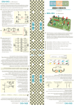
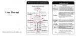
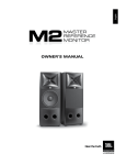
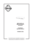
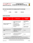
L210b
L210w
L310b
L310w
owner's manual
analog and digital systems
table of contents
introduction
speaker placement
mounting the speakers
wiring
speaker protection
maintenance
specifications
1
1
2
4
4
5
6
introduction
Thank you for purchasing an a/d/s/ L series mini-speaker system. The L210 and L310 are the latest
descendants of the original ADS mini-speaker which first introduced the concept of big sound from a
small box. The L210 and L310 produce superior sound with classic a/d/s/ drivers and advanced crossover
technology. The sonic realism, bass response, and output capabilities are remarkable for such compact
loudspeakers. The L210 and L310 are magnetically shielded and are supplied with mounting brackets.
This edition of a/d/s/ mini-speakers features new cast aluminum housings that are weather resistant,
allowing the L210 and the L310 to be permanently mounted outdoors. In addition, the L210 and L310
drivers are magnetically shielded so that they may be used indoors near television screens or computer
monitors. The L series mini-speaker systems will not only provide excellent performance when used
alone, but may also be combined with an a/d/s/ powered subwoofer to provide stunning full range high
output Audio/Video system performance. Clearly the L210 and L310 are two of the most versatile
speakers available. Any type of system, ranging from outdoor applications, to home theater systems,
to multimedia computers can take advantage of their exceptional performance.
Installing the L210 or L310 is not difficult. However, correct wiring and proper placement play a vital
role in optimizing sound quality. This manual provides information on the placement, connection and
operation of your loudspeakers. Please read it thoroughly and save it for future reference.
speaker placement
Where speakers are placed significantly affects their sound. Some general placement guidelines are
given below. However, since all situations are different you should experiment with various locations
to determine where they sound best.
Outdoor use
Although the L210 and L310 are “all weather” loudspeakers, when using them outdoors you will
extend their life and improve reliability if you avoid mounting them where they will be exposed to
direct sunlight for extended periods of time. The L210 and L310 will stand up to moderate amounts of
moisture. However, they should not be mounted will be directly exposed to heavy rain. In colder
climates, bringing your loudspeakers inside for the winter when they are not being used is advised.
Boundaries
In general, the L210 and L310 will produce the smoothest response and best stereo image when located
at least two feet from the room boundaries - that is, the floor, ceiling and walls. Moving the speaker
closer to one or more boundaries will increase the bass output. In some rooms, the extra bass will
enhance the sound. In others the extra bass will be too much, making the sound “boomy” or “tubby”.
Experimenting with speaker placement is the most important thing you can do to achieve the best
possible sound.
“Hard” surfaces near a speaker can affect the distribution of high frequency sound in the room. As a
result, the accuracy of the stereo image. If the speakers are near the corners, point the speakers
towards the center of the room. If the floor in front of the speakers is not carpeted, place a small area
rug in front of the speaker to reduce high frequency reflections and improve the stereo image. When
a speaker is on a shelf or tabletop, keep the front of the speaker flush with the edge of the supporting
surface if possible.
1
Height
Try to place the speakers so they are close to the same height as your ears when you are seated in the
preferred listening area. Also be sure the speakers are high enough that the sound they produce will
not be constrained by
Separation
Start at your preferred listening position with the speakers at the points of an equilateral triangle, aimed
toward the listening position. (See diagram.) Experiment with moving the speakers closer together and
varying the aiming angle until you get the stereo image you prefer.
At
least
2
feet
Approximate
height of
seated
listener's ear
Speaker orientation
Stereo imaging is generally best when a speaker’s long axis is vertical, but horizontal placement is by
no means ruled out. Try the speakers both ways to determine if the difference in sound is important
to you.
Any of the a/d/s/ mini-speakers can be placed on a shelf or other solid surface. If the speakers are placed
on a shelf, put the supplied adhesive-backed felt pads on the bottom of the cabinets. The pads protect
the surface under the speakers and reduce the possibility of rattles or buzzes. The L210 and L310 may
also be used freestanding.
mounting the speakers
Before mounting the speakers in brackets, plan the mounting location and method very carefully. Follow
the speaker placement guidelines described in the instruction manual and decide on the mounting
locations. If you plan to hide the speaker wires behind the mounting surface, route the wires before you
mount the brackets. See the following section for information on wiring.
2
How the brackets should be fastened to the mounting surface depends on the structure and material
of the mounting surface. There are two typical situations. One is with the brackets attached to a
conventional wall constructed with drywall material over wood studs. The other situation is with the
brackets mounted to a wood cabinet or some other solid material. When the speakers are mounted on
drywall the plastic screw anchors will be used in conjunction with the screws. When the speakers are
mounted on a solid panel the screws anchors will not be needed. Driving the screws directly into the
solid panel will provide a strong enough mounting.
The L-series speaker system is supplied with brackets for horizontal or vertical mounting. Pick the
correct bracket for your application, and set the bracket in the installation location. Be sure it is
straight. Using the bracket as a template, mark the location of the two mounting screw holes. Set the
bracket aside. If the plastic anchors will be used drill the holes for them with a 1/4" bit. If only the self
tapping screws are used, drill pilot holes with a 1/8" bit. Push the plastic screw anchors, if they are
being used, into the holes drilled for them. NOTE: If the speakers are being mounted horizontally the
opening in the end of the mounting brackets should be oriented upward.
3
Drive the mounting screws through the bracket, into the holes, until they are firmly set. Connect the
wire to the speakers (see wiring tips in following section). Set the speakers in the mounting brackets,
placing a rubber washer between the speaker cabinet and the bracket on each side. Secure the cabinet
to the brackets with the threaded knobs, placing a second rubber washer around the threaded part of
each knob. Position the speaker as desired, and tighten the knobs.
wiring
Wire
Use two-conductor stranded-type, insulated wire to connect the speakers to the amplifier. “Lamp” wire
or “zip cord” works well. If you are running wiring within the walls, make sure that it complies with
your local building codes pertaining to low-voltage wiring. Use at least 16 gauge for runs of less than
50 feet. Use 14 gauge or larger wire for longer runs. The resistance of 18 gauge or smaller wire can
cause a bass response peak if used for more than a few feet.
Preparing the wire
Estimate the amount of wire needed. Allow enough extra wire so you can move the speakers if
necessary. Separate the conductors of each wire pair a few inches in from the end. Strip about 3/8”
insulation from each conductor. Be careful not to cut into the wire itself. Twist the strands of the
conductor together to avoid fraying. For outdoor use, terminate the wire with gold-plated pin-type
terminals and insulate the wire-to-pin connection with silicone filled heat-shrink tubing. Bare copper
wire can corrode and cause unreliable connection over time.
Polarity
The polarity - the positive/negative orientation of the connections - for every speaker-to-wire and wireto-amplifier connection must be the same so the speakers will be “in phase”. If the polarity of one
connection is reversed, bass output is reduced and stereo imaging is degraded. All wire is marked so
you can identify the two conductors. There may be ribs or a stripe on the insulation of one conductor.
The wire may have clear insulation with different color conductors (copper and silver). Decide which
conductor you will use for “positive” and which for “negative”. Then be consistent with every speakerto-wire and wire-to-amplifier connection.
Speaker input connectors
The speakers have color coded push-to-connect input terminals that accept virtually all types of speaker
wire. Push the back of the terminal to open the wire access hole. Put the stripped wire or pin terminal
into the hole and release the terminal.
Making the connections
Connect the positive conductor of one wire to the red input connector of one speaker and to the red
or “+” speaker output connector of the associated amplifier channel. Connect the negative conductor of
the wire to the black terminal of the speaker and to the black or “-” connector of the associated
amplifier channel. Repeat the procedure for the other channel. Be sure to follow exactly the same
connection procedure for both channels.
speaker protection
The speakers have a solid-state, fully automatic tweeter protector. This device reduces the power to the
tweeter when the speaker is operated at unsafe power levels. The protector resets itself when power
is reduced to a safe operating level. If high power operation causes the tweeter to stop playing, turn
down the volume control until normal sound resumes. Note: The tweeter protector provides a significant
level of protection. However it does not guarantee that the tweeter cannot be damaged. Always be
careful when operating the speakers at a high volume level.
4
maintenance
The drivers require no routine maintenance. Do not let anything touch the drivers. Do not vacuum clean
the drivers or front panels of the speakers. Some dust accumulation on the drivers is normal and does not
affect the sound in any way. Heavy dirt buildup may be carefully removed with a soft paintbrush if
necessary.
The enclosures of your a/d/s/ speakers require no maintenance other than dusting. Dust the speakers
with a dry or slightly damp cloth. To clean the grills, remove them from the speaker and vacuum them.
Do not vacuum the grille while they are on the speakers.
Most difficulties with high fidelity equipment result from loose or poor connections, bad
connecting cables or switches in the wrong positions.
No sound It is rare for a speaker to fail completely. When there is no sound, check all the speaker wire
connections and the setting of the amplifier’s tape monitor or speaker selector switch.
Dull or muted sound Operating the speakers at an unsafe power level activates the automatic tweeter
protector. Turn down the amplifier volume control and the protector will automatically restore signal to
the tweeter. Also check the amplifier’s tone controls or “high filter” switch.
Distorted Sound Distortion at moderate levels can be caused by loose connections, or stray wire strands
shorting out adjacent wires at the amplifier or speaker terminals. If you hear distortion or any type of
buzzing or rattling sound from an individual driver, contact your a/d/s/ dealer. Distortion at high levels
is the result of either reaching the power limit of the amplifier or of the speaker. Turn down the volume
to prevent damage.
Noise or Hum Continuous background noise or hum are always from the electronic equipment and not
from the speakers.
5
specifications
L210
Driver complement
Frequency response:
Impedance:
1"/ 25 mm copolymer dome tweeter with a Ferrofluid™ cooled, oxygen
free copper voice coil wound on a Kapton® former.
4” / 104 mm high compliance tapered copolymer cone with butyl surround
and OFC voice coil wound on a Kapton® former.
85 - 20kHz, ± 3dB*
4 Ohms nominal.
Efficiency:
88 dB SPL from 2.8 VRMS (“1 Watt”) pink noise input at 1 meter.*
Crossover:
2.5 kHz with 12dB / octave slopes.
Recommended
amplifier power range:
Cabinet size:
10 Watts - 50 watts RMS.
7 1/8" h x 4 7/16" w x 5" d (including grille).
182mm h x 112mm w x 127mm d
*Measured under laboratory conditions.Specifications subject to change.
L310
Driver complement
Frequency response:
Impedance:
1"/ 25 mm copolymer dome tweeter with a Ferrofluid™ cooled, oxygen
free copper voice coil wound on a Kapton® former.
5 1/4” / 131 mm high compliance tapered copolymer cone with butyl
surround and oxygen free copper voice coil wound on a Kapton® former.
68 - 20kHz, + 3dB*
4 Ohms nominal.
Efficiency:
90 dB SPL from 2.8 VRMS (“1 Watt”) pink noise input at 1 meter.*
Crossover:
2.5 kHz with 12dB / octave slopes.
Recommended
amplifier power range:
Cabinet size:
10 Watts - 75 watts RMS.
8 11/16" h x 5 13/16" w x 6 1/8 " d (including grille).
220mm h x 148mm w x 156mm d
*Measured under laboratory conditions.Specifications subject to change.
6
warranty information
LIMITED FIVE YEAR CONSUMER WARRANTY FOR PRODUCT INSTALLED BY AN AUTHORIZED
LICENSED DEALER
Directed Electronics, Inc. promises to the original purchaser, to replace this product should it prove to be
defective in workmanship or material under normal use, for a period of five years from the date of
purchase from the dealer as indicated by the date code marking of the product PROVIDED the product
was sold by an authorized Directed dealer. During this five year period, there will be no charge for this
replacement PROVIDED the unit is returned to Directed, shipping pre-paid. This warranty is nontransferable and does not apply to any unit that has been modified or used in a manner contrary to its
intended purpose, and does not cover damage to the unit caused by installation or removal of the unit.
This warranty is void if the product has been damaged by accident or unreasonable use, neglect, improper
service or other causes not arising out of defects in material or construction. Units which are found to be
damaged by abuse resulting in thermally damaged voice coils are not covered by this warranty but may
be replaced at the absolute/sole discretion of Directed. ALL WARRANTIES INCLUDING BUT NOT
LIMITED TO EXPRESS WARRANTY, IMPLIED WARRANTY, WARRANTY OF MERCHANTABILITY,
FITNESS FOR A PARTICULAR PURPOSE , AND WARRANTY OF NON-INFRINGEMENT OF
INTELLECTUAL PROPERTY ARE EXPRESSLY EXCLUDED AND DISCLAIMED TO THE MAXIMUM
EXTENT ALLOWED BY LAW, AND DIRECTED NEITHER ASSUMES NOR AUTHORIZES ANY PERSON
TO ASSUME FOR IT ANY LIABILITY IN CONNECTION WITH THE SALE OF THE PRODUCT. DIRECTED
HAS ABSOLUTELY NO LIABILITY FOR ANY AND ALL ACTS OF THIRD PARTIES INCLUDING ITS
AUTHORIZED DEALERS OR INSTALLERS. Unit must be returned to Directed, postage pre-paid, with bill
of sale or other dated proof of purchase bearing the following information: consumer.s name, telephone
number, and address, authorized dealer.s name and address, and product description. Note: This warranty
does not cover labor costs for the removal and reinstallation of the unit. IN ORDER FOR THIS
WARRANTY TO BE VALID, YOUR UNIT MUST BE SHIPPED WITH PROOF OF SALE BY AN
AUTHORIZED DIRECTED DEALER. Some states do not allow the limitation on how long an implied
warranty lasts, so the above limitation may not apply to you. LIMITATION OF DAMAGES AND
LIABILITY: CONSUMER.S REMEDY IS LIMITED TO REPAIR OR REPLACEMENT OF THE UNIT, AND IN
NO EVENT SHALL DIRECTED.S LIABILITY EXCEED THE PURCHASE PRICE OF THE UNIT. IN ANY
EVENT, DIRECTED SHALL NOT BE LIABLE FOR ANY DAMAGES (INCLUDING, BUT NOT LIMITED TO,
ANY DIRECT, INDIRECT, INCIDENTAL, SPECIAL, PUNITIVE OR CONSEQUENTIAL DAMAGES, LOST
PROFITS, LOST SAVINGS, OR, TO THE EXTENT ALLOWED BY APPLICABLE LAW, DAMAGES
RESULTING FROM DEATH OR INJURY ARISING OUT OF OR IN CONNECTION WITH THE
INSTALLATION, USE, IMPROPER USE, OR INABILITY TO USE, THE PRODUCT, EVEN IF THE PARTY
HAS BEEN ADVISED OF THE POSSIBILITY OF SUCH DAMAGES. Some states do not allow the
exclusion of incidental or consequential damages, so the above limitation or exclusion may not apply to
you. BY PURCHASING THIS PRODUCT, THE CONSUMER AGREES AND CONSENTS THAT ALL
DISPUTES BETWEEN THE CONSUMER AND DIRECTED SHALL BE RESOLVED IN ACCORDANCE
WITH CALIFORNIA LAWS IN SAN DIEGO COUNTY, CALIFORNIA.
declaration of conformity
manufacturer name:
manufacturer address:
Directed Electronics Inc.
One Viper Way
Vista, California 92083
declares, that the product:
product name:
L210b
L210w
L310b
L310w
conforms to the following standards:
EN55013
EN55020
Directed Electronics, Inc. All rights reserved G39710/15/20/25 10-04
a