1
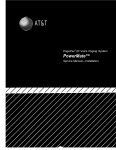
HARRIS CORPORATION
USER
MANUAL
TS21 CRAFT TEST SET
DESCRIPTION AND USE
NOVEMBER 1996
P/N 0II722333-001
Issue 5, November 1996
P/N 0II-722333-001
Issue 5, November 1996
USER MANUAL
TS21 Craft Test Set
Description and Use
November 1996
© HARRIS CORPORATION 1996
Printed in USA
HARRIS CORPORATION
P/N 0II-722333-001
Issue 5, November 1996
TS21 CRAFT TEST SET
DESCRIPTION AND USE
CONTENTS
PAGE
1.
GENERAL . . . . . . . . . . . . . . . . . . . . . . . . . . . . . . . . . . .
1
2.
DESCRIPTION . . . . . . . . . . . . . . . . . . . . . . . . . . . . . . .
1
3.
CONTROLS AND INDICATORS . . . . . . . . . . . . . . . . . .
2
4.
CONNECTIONS . . . . . . . . . . . . . . . . . . . . . . . . . . . . . . .
3
5.
OPERATION . . . . . . . . . . . . . . . . . . . . . . . . . . . . . . . . .
3
6.
MAINTENANCE . . . . . . . . . . . . . . . . . . . . . . . . . . . . . . .
4
A Housing
B Non-Slip Surface
C Keypad
E Test Cord
7
4
0
1
8
5
#
2
9
D Belt Clip
6
3
WARNING
Good safety practices prohibit the connection of the TS21
and similar test sets to 117 volts AC commercial electrical
power; and should the TS21 be connected to commercial
power, all warranties are immediately voided.
Figure 1 – Physical Characteristics
(e)
The test sets are equipped with several different cord
configurations (E). The line cords may be replaced
in the field (see sections 4 and 6.02).
1. GENERAL
1.01
The Harris Corporation’s Dracon Brand TS21 Craft
Test Set employs the latest technology in integrated
circuit design to provide both DTMF (Touch Tone) and dial
pulse output. The TS21 also provides last number redial, and
field replaceable line cords and belt clips. This Test Set, often
called a “butt-in,” is a self-contained, line-powered, portable
handset used by installers, repair technicians, and other
authorized personnel for line testing and temporary
communications.
2. DESCRIPTION
2.01
Physical Characteristics (Figure 1):
(a)
2.02
Specifications:
(a)
Electrical
Loop Limit
2 kΩ maximum at
48 VDC (nominal 20 mA
minimum loop current)
DC Resistance
(Talk Mode)
<300 Ω (similar to
WECO 10131A and BECO 801)
Monitor Impedance
Rotary Dial Output
Pulsing Rate
Percent Break
Interdigit Interval
Leakage During Break
DTMF Output
Tone Frequency Error
Level per Tone Pair
6 kΩ minimum at 1 kHz
The housing (A) is injection molded of high impact
polycarbonate which provides excellent insulating
properties. The case is designed to give rugged service and
withstand the rough handling and shocks normally
associated with craft tools.
(b)
(b) The back of the hand grip (B) is contoured and has
a non-slip surface, freeing both hands while the Test
Set rests on the shoulder.
Length
Width
Height
Weight
(c)
(c)
The keypad (C) has 12 buttons on a black plastic
bezel that is recessed into the receiver end of the
housing. The recessed bezel provides physical protection
to the keypad and prevents accidental button operation.
High versus Low Tone
Difference
10 pps + 0.5 pps
61% ± 2%
1000 ms typical
>50 kΩ
± 1% maximum
+1 dBm maximum
–9 dBm minimum
4 dB maximum
Physical
9-11/16 inches (24.6 cm)
2-11/16 inches (6.83 cm)
3-11/16 inches (9.37 cm)
21 ounces (.600 kg) typical
Environmental
Temperature
Altitude
Relative Humidity
Operating: –34 to 60 °C
Storage: –40 to 66 °C
To 10,000 feet
5 to 95%
(d) The spring-loaded belt clip (D), located on the
transmitter end of the housing, ensures a secure
connection to a belt loop or D-ring. The belt clip may be
replaced in the field (see section 6.01).
Specifications subject to change without notice.
Page 1
2.03
Standard TS21 Models:
three-conductor ground start cord, initiating a ground start
line seizure.
*Model No.
**Cord Type
Ground Start Switch
21800-081
STD
NO
21800-082
SBN
NO
(a)
21800-084
SP
NO
21800-087
3W
YES
tones or dial pulses, depending on the MODE switch
setting. See (b).
21800-088
SPR
NO
21800-089
ABN
NO
*Special production models are indicated by a number in place of the zero following
the “-”, -180, -281, -384, etc. These models are identical to their corresponding
standard model, except for color and logo.
**See cord descriptions, Section 4.
3.02
Keypad Controls and Indicators (Figure 3):
(b)
3.01
Voice and polarity controls (Figure 2):
(a)
Talk/Monitor (T/M) Switch. This rocker switch
is located on the side of the test set. The T (TALK)
position establishes an off-hook condition for dialing and
talking as a common battery telephone. The M
(MONITOR) position removes the transmitter from the
circuit, and provides a high impedance coupling to the
line. The M position allows line monitoring without
disrupting conversations, data, or signaling.
Talk/Monitor Switch
Mute Button
Ground Start Button
(Model No. 21800-087)
Polarity Button
Figure 2 – Voice and Polarity Controls
(b)
Mute (M) Button. This non-locking push button,
labeled M, is located on the inside of the hand grip
just above the transmitter. When pressed, this button
mutes the transmitter, eliminating sidetone, and providing
improved intelligibility through the receiver in noisy
locations.
MODE Switch. This two-position locking rocker
switch, labeled MODE, is located on the lower-right
keypad bezel. The switch selects the signaling output:
TONE for DTMF or PULSE for dial pulse.
(c)
3. CONTROLS AND INDICATORS
Keys. The 12 standard keys will send either DTMF
Keypad Switch. This two-position locking rocker
switch, labeled KEYPAD, is located on the lower
left keypad bezel. With the switch in the IN position, the
Test Set operates as a telephone; this mode is used for all
normal communications. The OUT position bypasses the
Test Set circuitry, including the keypad. In this mode,
signaling is not possible, but the TS21 will operate at very
low voltages, much like standard Test Sets currently in
use. The OUT position is recommended when testing at
or near the loop limit (2,000 ohms at 48 volts DC), or when
testing on dry circuits. The OUT position must be used
when the circuit voltage is six volts or less, such as when
using tones or other test devices as a source of talk battery.
(d)
Polarity LEDs. These round LEDs, one green and
one red, are located at the top of the keypad. One
LED will illuminate when the polarity button is pressed,
to indicate line polarity. See section 5.02. The green LED
will light if the red test lead is connected to the ring
(negative) side of the line and the black test lead is
connected to the tip (positive) side of the line. The red LED
will light if the test leads are reversed; that is, with the red
test lead connected to the tip (positive) side and with the
black test lead connected to the ring (negative) side.
CAUTION: Operation of the P button on a busy circuit
may cause annoying clicks or service interruptions.
(e)
Last Number Dialed (#) Button. The # (pound)
key serves as a last number dialed button when the
(c)
Polarity Button. This non-locking push button,
labeled P, is located on the inside of the hand grip
just below the receiver. When pressed, the button will
activate one of the polarity LEDs, located at the top of the
keypad, showing the current polarity of a telephone line
or a low voltage battery source. See section 3.02(d).
1
2
3
4
5
6
7
8
9
0
#
(d)
Ground Start Button (optional). Located
between the MUTE button and the Polarity switch.
When pressed, this small black button connects the ground
(green) lead to the ring (red) lead of the special
Page 2
Figure 3 – Keypad
MODE switch is in the PULSE position. Pressing the #
key will redial the last number dialed.
test cords equipped with the matching 471A male
connector. Cord Number: P3218-233.
Note: The redial memory has a two minute time limit
(e)
to the standard (STD) cord, except that each
alligator clip is equipped with a bed-of-nails in addition
to an insulation piercing spike, and the clips are not offset
as are the STD clips. Cord Number: P3218-024.
after the TS21 has been disconnected from a working
telephone line. After two minutes, the number will be lost
from memory.
4. CONNECTIONS
4.01
(f)
Ground Start Cord (3W). This cord consists of
one red, one black, and one green fabric covered
tinsel conductor approximately five feet long, each fitted
with an alligator clip of the type used on the standard cord.
Pressing the GROUND START button connects the green
(ground) conductor to the red (ring) conductor inside the
Test Set. Cord Number: P3218-025.
Cords (Figure 4):
(a)
Bed-of-Nails Cord (SBN). This cord is identical
Standard Cord with Piercing Pin (STD). This
cord consists of one red and one black conductor,
each approximately five feet long. Each conductor is fitted
with an alligator clip offset 20° to minimize clip shorting.
The clips have insulation piercing spikes and a neoprene
boot. Cord Number: P3218-028.
5. OPERATION
(b)
5.01
Angled Bed-of-Nails Cord (ABN). The angled
Bed-of-Nails cord is similar to the STD cord, except
that each alligator clip is equipped with a “bed-of-nails”
in addition to the insulation piercing spike. Cord Number:
P3218-234.
(c)
Central Office Plug Cord (SP). This cord is
fitted with a type 346A female plug and is
approximately one foot long. The plug allows the use of
a variety of different test cords equipped with the
matching 471A male connector. Cord Number:
P3218-232.
(d)
Central Office Plug and Resistor Cord (SPR).
This cord is fitted with a type 346A female plug and
switchable 1500 ohms resistor, and is approx- imately 18
inches long. When switched on, the resistor is inserted in
series with the ring side of the cord to simulate a long loop
condition. The plug allows the use of a variety of different
PIERCING PIN CORD (STD)
P3218-028
Monitoring. Move the T/M switch to M (KEYPAD
IN/OUT and MODE switches may be in either
position), and connect the line leads to the telephone line under
test. Monitoring may now be done without disrupting traffic.
Note: The TS21 is not polarity sensitive and will function normally
regardless of telephone line polarity.
5.02
Polarity Check. Move the T/M switch to M. Connect
the line leads to the telephone line under test. Verify
that the telephone line is idle. Press and hold the depressed P
button. The green LED will light if the red test lead is connected
to the ring (negative) side of the line and the black test lead is
connected to the tip (positive) side of the line. The red LED will
light if the test leads are reversed; that is, with the red test lead
connected to the tip (positive) side and with the black test lead
connected to the ring (negative) side.
C.O. 346A PLUG CORD (SP)
P3218-232
ANGLED BED OF NAILS CORD (ABN)
P3218-234
C.O. 346A PLUG AND RESISTOR CORD (SPR)
P3218-233
BED OF NAILS CORD (SBN)
P3218-024
GROUND START CORD (3W)
P3218-025
Figure 4 – Cords
Page 3
CAUTION: Operation of the POLARITY button on a busy
c ir c uit may cause annoying clicks or ser vice
interruptions. Operation of the switch on an idle
telephone line may cause telephone line seizure.
5.03
Dialing.
(a)
Move the KEYPAD switch to the IN position. Move
the MODE switch to either TONE or PULSE,
depending on the type of dial signaling required. Move
the T/M switch to the M position. Connect the line cord
clips to the telephone line. Listen to verify that the
telephone line is idle.
5.07
Troubleshooting. The following troubleshooting
procedures are based largely on the audible click heard
in the receiver of the TS21 when the two Test Set leads are placed
on battery potential and ground respectively, or across the
terminal of an electrically charged capacitor. These clicks and
other sounds can greatly help a skilled crafts person in locating
open circuits, shorts, crosses, and grounds.
(a)
To locate a short circuit, open one side of the
telephone line and place the test set in the loop – one
lead to each side of the opened line. On the CO side of the
fault, a loud click will be heard; on the field side of the
fault, no click will be heard.
(b)
Move the T/M switch to T position and verify that
dial tone is received (when furnished). Enter the
desired number to be called on the keypad. If tone
signaling has been selected, the tones associated with each
digit will be generated as each respective button is pressed.
If rotary dial pulse signaling has been selected, the desired
number may be entered at any rate on the keypad; digits
will automatically be pulsed out at the correct rate. To end
the call, return the T/M switch to the M position.
(b)
Locating an open circuit is done by bridging the test
set across the circuit line – one test lead on tip, the
other on ring. Moving away from the CO, the fault is at
the point where the loud click disappears.
(c)
Continuity of each side of the loop may be verified
by placing one of the line leads on a local ground
and the other on the conductor in question. On a good ring
conductor, a click will be heard; on a good tip conductor,
an inductive hum will be heard (due to the difference in
ground potential between the CO ground and the local
ground).
5.04
Last Number Redial. Move the MODE switch to the
PULSE position. The last number dialed can be
automatically redialed by using the following procedure (the
number cannot exceed 18 digits):
(a)
Go on-hook (move the T/M switch to the M
position) for at least 1/2 second.
(b)
Move T/M switch back to T position.
(c)
Press the # (pound) key and the number will be
automatically redialed.
In the off-hook mode, if any key other than the # button is pressed,
the previously stored number will be erased.
Note: The redial memory has a two minute time limit after the Test
Set has been disconnected from a working telephone line. After two
minutes, the number will be lost from memory.
5.05
Ground Start Line Seizure (optional). Pressing the
GROUND START button connects together the
ground (green) and ring (red) leads of the three-conductor test
cord.
5.06
Note: For a full discussion on these troubleshooting procedures,
refer to your company’s practices, or to ABC of The Telephone,
Volume 2, Chapters 13, 14, and 15.
CAUTION: When testing circuits that are relatively close
to the battery source, the clicks may be loud enough to
cause temporary acoustical shock if the receiver is held
too tightly against the ear. The TS21 is designed to rest
comfortably on the shoulder with the receiver away from
the ear. It should be used in this position when listening
for clicks.
6. MAINTENANCE
6.01
Belt Clip Replacement. The belt clip may be easily
replaced in the field without opening up the Test Set.
The ordering number for the replacement belt clip is P3218-249.
To replace the belt clip assembly:
(a)
Operation On Low Voltage or Dry Circuits.
(a)
Move the keypad switch to OUT. This position
bypasses the circuitry of the Test Set and increases
the loop limit. The keypad will not operate in this mode,
but all other functions operate normally.
Move the T/M switch to M. Connect line leads to the
circuit under test. Verify that the circuit is idle.
Move the T/M switch to T for two-way communications.
(b)
Move the clip of the belt clip into an upward position
to expose the two mounting screws, and remove the
screws. Remove and discard the old belt clip.
(c)
Position the new belt clip so that its screw mounting
holes line up with the mounting holes in the Test
Set. Insert the screws and tighten.
(b)
When operating on low voltage or dry circuits, a
minimum of three volts DC talking battery is
required.
Place the Test Set on a firm and level working
surface with the keypad up.
Note: Be careful not to over tighten.
(c)
Page 4
6.02
Line Cord Replacement. The line cord may be
replaced in the field by experienced personnel, as the
Test Set must be opened up exposing its electronic circuit boards.
To replace the line cord:
(a)
Place the Test Set on a firm and level working
surface with the keypad up.
(b)
Remove the five housing screws, located:
– One above the keypad,
– One below the keypad on the hand grip,
– One above the belt clip on the hand grip, and
– Two on either side of the belt clip.
(c)
Carefully separate the upper housing from the lower
housing.
CAUTION: When separating the two housings, be careful
of the connecting leads between the two housings. Place
the two housings side-by-side, with the keypad and
transmitter-receiver sides down, to minimize any strain
on these leads.
(d)
Remove the two line cord lead screws on the circuit
board, near the belt clip end. Gently pull the cord
free of any obstructions. Remove and discard.
(e)
Position the individual lead tips of the new line cord
so that the tips line up with the screw holes in the
circuit board. The red lead to the right screw, labeled R
(Ring), and the black lead to the left screw, labeled T (Tip).
Insert the screws and tighten.
Note: Be careful not to over tighten the screws.
(f)
Position the brass line cord strain relief bushing or
ring on the line cord so that it is inside the housing
and lines up with the line cord exit hole.
(g)
Carefully close the two housings together, being
careful not to pinch any of the wires. Insert the five
housing mounting screws, and tighten.
Warranty
6.03
Harris Corporation warrants that the test set unit shall
be free of any defects in parts or workmanship, for a
period of 18 months and the line cord for a period of twelve (12)
months from the date of manufacture, if used under Harris
operating specifications.
THIS IS THE ONLY WARRANTY MADE BY HARRIS
CORPORATION AND IS MADE EXPRESSLY IN LIEU
OF ALL OTHER WARRANTIES EXPRESS OR IMPLIED, INCLUDING BUT NOT LIMITED TO ANY
IMPLIED WARRANTIES OF MERCHANTABILITY OR
FITNESS FOR ANY PARTICULAR PURPOSE.
Should any parts or workmanship prove defective, Harris Corporation will repair with not used or reconditioned parts, or replace the
Product, at Harris’ option, at no cost to the Buyer except for Shipping
costs from the Buyer’s location to Harris’ location. This is the
Buyer’s SOLE AND EXCLUSIVE REMEDY under the agreement.
6.04
This warranty does not extend to products which have
been subjected to neglect, accident or improper use, nor
to units which have been altered or repaired by other than
authorized Harris Corporation personnel.
Return Of Equipment
6.05
To return the Test Set to Harris, first obtain a Return
Authorization Number from our Customer Service by
calling 1-800-437-2266. This Return Authorization number
must be clearly marked on the shipping label, or the container
will not be accepted by Harris. See the sample label below:
To: HARRIS CORPORATION
809 Calle Plano
Camarillo, California 93012-8516
Attention: Customer Support, RA #XXXXXX
Note: Be careful not to over tighten the screws.
CAUTION: Do not use CRC Cable Clean® or any similar
chlorinated solvent on the TS22. Doing so will damage the
test set.
Page 5
HARRIS CORPORATION
809 Calle Plano – Camarillo, California 93012-8516
Telephone (805) 987-9511, FAX (805) 987-2547