Transcript
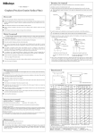
【Installing The Graplate】
Install the granite surface plate and its dedicated steel stand on a sufficiently resistant foundation.
《When using the standard steel stand or drop prevention stand for installation》
― User’s Manual -
① Install the stand on the floor. Adjust the foot height using the adjusting bolts so that the four feet do not
rattle.
Standard Steel Stand, Drop Prevention Stand,
and Caster Wheel Stand for Graplate
(Precision Granite Surface Plate)
Support leg
Auxiliary leg
※ Auxiliary legs are not provided
for stands that are 1000×750mm or
smaller.
Adjusting bolt
Dedicated
steel stand
【Foreword】
Thank you very much for purchasing our standard steel stand, drop prevention stand, or caster wheel stand
for the granite surface plate.
● This User’s Manual provides notes on using the granite surface plate. To effectively use and maximize
the performance of the plate, read through this manual.
② Install the granite surface plate onto the stand by using a crane or other machine.
!
WARNING
Because the surface of the granite surface plate is very slippery, be extremely careful when installing
the plate.
When installing the granite surface plate onto the drop prevention stand, be careful not to allow the plate
to contact the drop prevention plate.
● After reading this manual, always keep it near the stand so that you can refer to it anytime.
● Note that we bear no responsibility for financial loss caused by using this stand.
● The contents of this manual are subject to change without notice.
!
WARNING
Position the granite surface plate and drop prevention plate so that the gap between them is 10 mm or less.
If the gap is larger, you could catch your finger in it or get injured.
【Safety Precautions】
!
WARNING
If the granite surface plate and drop prevention plate collide, a breakage or other problem might result
in injury. Carefully install the plate.
To maximize the stand performance and work safely, note the following. We bear no responsibility
for any accident or failure caused by breaking these rules.
!
WARNING
Be careful not to insert a workpiece or finger between the drop prevention plate and granite surface
plate. If the granite surface plate moves, the workpiece might be broken or you could catch your
finger between the plates or get injured.
● This stand is designed for installing the granite surface plate. Do not use it for other purposes.
● Do not put unnecessary items on this stand.
● Do not touch the drop prevention plate or caster wheel during measurement or relocation. You could
catch your hand in it or otherwise get injured.
● Do not shake the stand.
● The operator must wear carefully chosen clothes, especially shoes. Never wear slippers. Wear safety
shoes.
③ Align the centers of the support feet on the dedicated steel stand and the foot rests glued to the bottom
surface of the granite surface plate.
Graplate
(Size:1000×1000mm or larger)
Graplate
(Size:1000×750mm or smaller)
【Moving The Caster Wheel Stand】
① Make sure that there are no items on the granite surface plate.
!
WARNING
Foot
Support leg
Adjusting bolt
Fixed nut
Dedicated steel stand for large scale
Foot
② Loosen the four adjusting bolts to allow the caster wheels to move.
Support leg
!
φ10 hole
Fixed nut
Dedicated steel stand for small scale
※ Rotate the supporting leg by using the
φ10 hole and adjust height.
④ Put a level on the working face of the granite surface plate and level the face by adjusting the height of
the three support feet. After leveling the face, tighten the fixing nuts. If you are installing a granite surface
plate that requires auxiliary feet, lightly push them against the bottom surface of the plate. Do not
strongly push them because this will change the accuracy of the working face.
Do not touch the caster wheels. Doing so might cause an injury.
WARNING
③ Make sure that the gap between the drop prevention plate and the granite surface plate is within 10 mm,
and then move the granite surface plate.
!
WARNING
※ Rotate the adjusting bolt and adjust
height.
Always move the granite surface plate and workpieces separately. Moving a plate on which a
workpiece sits is extremely dangerous.
The granite surface plate might shift during relocation. Minimize the gap between the drop
prevention plate and granite surface plate to ensure safety. Never move the granite surface plate while
holding the drop prevention plate. This is extremely dangerous because you could catch your hand
between them or otherwise get injured.
④ Fix the stand in place by using the four adjusting bolts to prevent rattling.
⑤ Set and level the beam.
【Specifications】
《When using the caster wheel stand for installation》
H
① Install the stand on the floor. Keep the caster wheels off the ground by using adjusting bolts so the stand
does not move.
!
Graplate
L
A
Be sure to fix the stand in place by using the adjusting bolts before installing the caster wheel stand.
h
WARNING
K B
② Remove all drop prevention plates. (They are fixed in place with two M10 screws.)
Dedicated steel stand
③ Install the granite surface plate onto the stand by using a crane or other machine and then set and level the
beam. (For details, see the procedure for the standard steel stand above.).
④ Install the drop prevention plates by using the two M10 screws removed in step (2) above.
⑤ Position the granite surface plate and the drop prevention plate so that the gap between them is 10 mm or
less. If the gap is larger, you could catch your finger in it or get injured.
!
WARNING
Be careful not to insert a workpiece or finger between the drop prevention plate and granite surface
plate. If the granite surface plate moves, the workpiece might be broken or you could catch your
finger between the plates or get injured.
Standard Steel
Stand
517-203
517-204
517-205
517-206
517-207
517-208
517-209
517-210
Code No.
Drop
Prevention
517-203R
517-204R
517-205R
517-206R
517-207R
517-208R
517-209R
517-210R
Dimensions of Graplate (mm)
Caster Wheel
Stand
517-203CR
517-204CR
517-205CR
517-206CR
517-207CR
517-208CR
517-209CR
517-210CR
《Accessory》 User’s Manual (1 PC.)
A×B×H
K
600×450×100
370
600×600×130
500
750×500×130
420
1000×750×150 630
1000×1000×150 700
1500×1000×200 700
2000×1000×250 600
2000×1500×300 1100
L
Height
h(mm)
500
500
630
700
700
1100
1500
1500
755~775
755~775
755~775
755~775
755~775
755~775
755~775
755~775
Weight of
Graplate
(kg)
80
140
146
337
450
900
1,500
2,700