1
AMS III
Advanced Microstepping Controller
User Manual Rev. 2.0.0
AMS III 1.0.0
February 2014
(C) Digital Technology Art srl 2014, All Rights Reserved
Copyright 2014 Digital Technology Art s.r.l.
All rights reserved. The reproduction of any part of this manual is allowed only with the written
authorization by Digital Technology Art s.r.l..
The contents of this manual may be subject to changes without any warning.
Digital Technology Art are not responsible for errors that may occur in this manual.
2
AMS III User Manual © 2010 Digital Technology Art srl
Summary
AMS III ................................................................................................................................................ 1 INTRODUCTION ............................................................................................................................. 5 CONNECTORS ON THE BOARD ................................................................................................ 6 I/O CONNECTOR Y17 ................................................................................................................... 7 Y14/15 MOTOR OUTPUT ......................................................................................................... 7 I/O ELECTRICAL SCHEME .......................................................................................................... 8 SERIAL CONNECTION .................................................................................................................. 9 SERIAL PROTOCOL ..................................................................................................................... 11 COMMAND LIST............................................................................................................................ 13 SERIAL COMMANDS ............................................................................................................... 14 REV................................................................................................................................................ 14 HST ............................................................................................................................................... 14 MMC .............................................................................................................................................. 15 RMC ............................................................................................................................................... 15 OFF ................................................................................................................................................ 16 THS ............................................................................................................................................... 16 RTH ............................................................................................................................................... 17 EEW............................................................................................................................................... 17 EWW ............................................................................................................................................. 18 ELW ............................................................................................................................................... 18 EDW .............................................................................................................................................. 19 EER ................................................................................................................................................ 19 EWR .............................................................................................................................................. 20 ELR ................................................................................................................................................ 20 EDR ............................................................................................................................................... 21 ILP ................................................................................................................................................. 21 OLP ................................................................................................................................................ 22 MEN ............................................................................................................................................... 22 SME ............................................................................................................................................... 23 FRC ................................................................................................................................................ 23 CMF ............................................................................................................................................... 24 RES................................................................................................................................................ 24 MPF................................................................................................................................................ 25 SMF ............................................................................................................................................... 25 ESF ................................................................................................................................................ 26 AMS III User Manual © 2010 DTA srl
3
SEF ................................................................................................................................................ 26 ECT ................................................................................................................................................ 27 SEC................................................................................................................................................ 27 POS ............................................................................................................................................... 28 PCT ................................................................................................................................................ 28 TRK................................................................................................................................................ 29 ETK ................................................................................................................................................ 29 TKS ................................................................................................................................................ 30 IOP ................................................................................................................................................ 30 SOC ............................................................................................................................................... 31 STO ............................................................................................................................................... 31 GTL ................................................................................................................................................ 32 DAC ............................................................................................................................................... 32 SRC ............................................................................................................................................... 33 RTC................................................................................................................................................ 33 JOY ................................................................................................................................................ 34 EDE ............................................................................................................................................... 34 SID ................................................................................................................................................ 35 Cyclic redundancy check .......................................................................................................... 37 Introduction ............................................................................................................................... 37 CRCs and data integrity ........................................................................................................ 37 Computation of CRC ............................................................................................................... 38 Mathematics of CRC ............................................................................................................... 38 Specification of CRC ............................................................................................................... 39 Commonly used and standardized CRCs ....................................................................... 39 Designing CRC polynomials ................................................................................................. 42 4
AMS III User Manual © 2010 Digital Technology Art srl
INTRODUCTION
AMS is a control system for the management of step motors of little size up to 2.8A a phase.
It can manage two motors simultaneously, both for positioning and tracking.
AMS implements two types of architecture:
1)
“open-loop”: the quantization of the movement has done by the step-step motor of
which is known the angular movement related to an impulse;
2) “close-loop”: the quantization of the movement has done by the resolution of the
encoders.
The management of the motors is based on the microstepping tecnique.
This mode allows to set the angular step by software, starting from maximum value of 200000
step/rev up to minimum of 400 step/rev.
In practice, it’s as if you have a de-multiplication ratio varying electronically.
Moreover, the system allows to vary the power used by the motors from a minimum of 0%
(0A) to maximum 100% (2.8A).
Another characteristic of the system is that it can execute arbitrary trackings on both the
controlled axes.
At last, one of the more interesting characteristics offered by this system is the possibility to
use it in cascade with other AMS devices, up to a maximum of 256 devices.
In fact, each AMS has got a own identity number (00-255), so being possible to control up to
512 motors by just one serial port.
AMS III User Manual © 2010 DTA srl
5
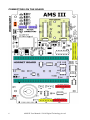
CONNECTORS ON THE BOARD
6
AMS III User Manual © 2010 Digital Technology Art srl
I/O CONNECTOR Y17
I/O SIGNALS
OPEN COLLECTOR
OUTPUT
TTL-OUT-1
TTL-OUT-3
TTL-IN-1
TTL-IN-3
RX0
(DTR) RX1
ENCODER-0-B
ENCODER-1-B
OPTO-IN-1
L-OPTO-IN-1
L-OPTO-IN-3
GND
SCHEMATIC
SIGNALS
OC1
PIN
PIN
I/O SIGNALS
2
SCHEMATIC
SIGNALS
+5V
1
P4_27
P4_29
P1_27
P1_29
S2
S4
INO1
INO3
INO5
INO7
INO9
GND
3
5
7
9
11
13
15
17
19
21
23
25
4
6
8
10
12
14
16
18
20
22
24
26
P4_26
P4_28
P1_26
P1_28
S1
S3
INO0
INO2
INO4
INO6
INO8
COMOPTO
TTL-OUT-0
TTL-OUT-2
TTL-IN-0
TTL-IN-2
TX0
TX1 (RTS)
ENCODER-0-A
ENCODER-0-A
OPTO-IN-0
L-OPTO-IN-0
L-OPTO-IN-2
COMOPTO
+5V
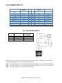
Y14/15 MOTOR OUTPUT
PIN
SIGNAL
1
2
3
4
COIL1A
COIL2A
COIL1B
COIL2B
MOTOR WIRE
COLOUR
Orange
Blue
Red
Yellow
Y2 – Power control switch. Close this contact to turn on AMS, or always leave inserted a
jumper to automatically turn on with the main power.
Y12 – TTL input ROW[0:7]. If use the keyboard MK-25 ROW[0:3] are reserved for this use.
Y13 – TTL output COL[0:7]. If use the keyboard MK-25 COL[0:5] are reserved for this use.
Y20 – TTL output OUT[0:7]. General purpose output.
AMS III User Manual © 2010 DTA srl
7
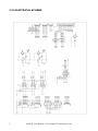
I/O ELECTRICAL SCHEME
8
AMS III User Manual © 2010 Digital Technology Art srl
SERIAL CONNECTION
AMS works by a RS232 serial port, the default setting is 115200,8,N,1; you can set different
values by the configuration program.
AMS can be connected point-point or in cascade (in latter way, you can control up to 256
devices by just one serial port)
Personal computers offer one or more serial ports, generally of two different types: 9PIN or
25PIN (look at the image below).
We need just three of all present signals:
1. Receive data
2. Transmit data
3. Signal ground
Depending on the type of connector, these signals are in different pins, look at the table below,
where the arrangement of the pin is shown.
DB9
DB25
Function
1
8
Data carrier detect
2
3
Receive data
3
2
Transmit data
4
20
Data terminal ready
5
7
Signal ground
6
6
Data set ready
7
4
Request to send
8
5
Clear to send
9
22
Ring indicator
AMS III User Manual © 2010 DTA srl
9
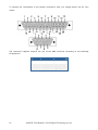
To identify the numeration of the RS232 connector’s pins, the images below can be very
useful:
The connector supplied requires the use of the DB9 connector according to the following
arrangement:
10
DB9 PC
DB9 AMS
PC Function
2
2
Receive data
3
3
Transmit data
5
5
Signal ground
AMS III User Manual © 2010 Digital Technology Art srl
SERIAL PROTOCOL
To communicate with AMS III means sending and receiving messages, typically only text
messages in ASCII format.
We said “typically” since the user can define the protocol, so it is possible that he will use nottext characters for communication.
What we are going to describe is the protocol default set during the final testing of the device.
The serial protocol uses three types of fields:
1. Control, this type is used for:
a. Identity, it indicates the basic address identifying the AMS corresponding to the
message destination; it generally consists of maximum two digits.
b. Separator, it is a character utilized to logically separate the fields between
them.
c. End of the message, it is a character indicating the end of the message.
2. Command, it is composed by three ASCII characters and it identify the command the
AMS has to run.
3. Parameter/s Zero or a maximum 15 specifics parameters of the command to run.
Here below a practical example of how a command sent to AMS can be composed:
IDENTITY
CONTROL
SEPARATOR
CONTROL
COMMAND
SEPARATOR
CONTROL
PARAMETER 1
SEPARATOR
CONTROL
...
SEPARATOR
CONTROL
PARAMETER N
END OF
MESSAGE
CONTROL
Let’s see a real message:
0,REVCR
in C language the string is defined as follows:
“0,REV\r”
Analyzing it:
The character ‘0’ is the identifying number of AMS, the character ‘,’ is the separator, ‘REV’ is
the command, ‘\r’ e’ is the character of control of end string.
If you are using only one AMS by the serial port, it is possible to skip the CONTROL IDENTITY,
so the previous message becomes:
“REV\r”
AMS III User Manual © 2010 DTA srl
11
You can even use this modality when there are many AMS connected by the same serial port;
however, you have take into account that only the one directly connected to the serial port of
the system is able to receive the commands.
At the contrary, it could be useful to send the same commands to all the AMS connected, you
can do it indicating the sequence of characters ‘##’ instead of the the NUMBER IDENTITY, so
the message becomes:
“##,REV\r”
There is even the possibility to enable a control for the integrity of the messages; to do it, by a
command you can enable the generation and control of a 16 bit CRC.
This type of control gives a high reliability on the integrity of the received message.
If we enable the CRC, the previous message becomes:
0,REV,18149CR
The characters highlighted in yellow are the ones used for the computation of CRC.
In case the received CRC is different from the one calculated, the response is:
0,CRC,55991CR
Instead, if the CRC is right, we receive:
0,100,55487CR
In Appendix A you can find an example on how to calculate the CRC used by AMS.
More info on CRC at Appendix 2 or on the website:
http://en.wikipedia.org/wiki/Cyclic_redundancy_check
It’s very important to underline the first parameter indicated by
AMS in the response message is its identity number.
12
AMS III User Manual © 2010 Digital Technology Art srl
COMMAND LIST
In the following pages is a complete list of commands executed by AMS.
All examples assume that:
-
the number of identity of the AMS is 0
-
the DECIMAL modality is active
-
the separator used is the comma
-
the end character is the CR (13)
-
the CRC control is disabled.
Differently from above, it would change the parameter coding
or response coding.
DIGITS indicates the number of hexadecimal digits, when the HEX mode is active.
For all commands that return a status these are the possible messages:
TEXT
INDEX
DESCRIPTION
ACK
0
NAK
1
Successfully executed command
Not recognized command
BPN
2
Wrong number of parameters
Parameter out of range
POR
3
UNS
4
Not supported mode
CRC
5
CRC failure on received string
As for the commands, the error codes can be text type or numeric index depending on the
choice of the user; you can switch from one type to the other by the use of VRB command.
AMS III User Manual © 2010 DTA srl
13
SERIAL COMMANDS
REV
COMMAND
TEXT
REV
DESCRIPTION
INDEX
000
PARAMETER
#
Digits Minimum Value
Return the remote management program
revision
DESCRIPTION
Maximum
Value
-
RETURN
DESCRIPTION
#
Digits
Value
0
2
0-255
AMS identifier
1
4
100-1000
Program revision
DETAIL
Command used to know the program revision. If it returns the value 100, it means 1.0.0
EXAMPLE
REVCR
0,100CR
HST
COMMAND
DESCRIPTION
TEXT
INDEX
HST
001
Return the temperature of the heatsink
PARAMETER
DESCRIPTION
#
Digits
Minimum Value Maximum
Value
RETURN
DESCRIPTION
#
Digits
Value
0
2
0-255
AMS identifier
1
2
0-255
Heatsink temperature
DETAIL
Command used to know the operating temperature of the heatsink in degrees centigrades
EXAMPLE
HSTCR
0,27CR
14
AMS III User Manual © 2010 Digital Technology Art srl
MMC
COMMAND
DESCRIPTION
TEXT
INDEX
MMC
002
Set the max current of the motors
PARAMETER
DESCRIPTION
#
Digits
Minimum Value Maximum
Value
0
2
0
1
Motor.selection.
1
4
0
2800
Max current of the motor in mA
RETURN
DESCRIPTION
#
Digits
Value
0
2
0-255
AMS identifier
1
2
CODE
Operation result
DETAIL
Command used to set the maximum current of the motors
EXAMPLE
MMC,0,2000CR
0,ACKCR
RMC
COMMAND
TEXT
RMC
DESCRIPTION
INDEX
003
Return the maximum current of the used
motors
DESCRIPTION
PARAMETER
#
Digits
Minimum
Maximum
Value
Value
0
2
0
1
Motor.selection.
RETURN
DESCRIPTION
#
Digits
Value
0
2
0-255
AMS identifier
1
4
0-2800
Current in use in mA
DETAIL
Command used to know the maximum current in use on the selected motor
EXAMPLE
RMC,0CR
0,2000CR
AMS III User Manual © 2010 DTA srl
15
OFF
COMMAND
TEXT
INDEX
OFF
004
PARAMETER
#
Digits
Minimum Value Maximum
Value
DESCRIPTION
RETURN
#
Digits
0
2
1
3
DETAIL
By this command you can turn
EXAMPLE
OFFCR
DESCRIPTION
Value
0-255
OFF
Turn off the AMS
DESCRIPTION
AMS identifier
off the AMS by remote connection
0,OFFCR
THS
COMMAND
DESCRIPTION
TEXT
INDEX
THS
005
Temperature threshold to start on the fan
PARAMETER
DESCRIPTION
#
Digits
Minimum Value Maximum
Value
1
2
0
99
Temperature in degrees centigrades
RETURN
DESCRIPTION
#
Digits
Value
0
2
0-255
AMS identifier
1
2
CODE
Operation result
DETAIL
Set the temperature threshold measured on the inner heatsink in the order to turn on the
fan
EXAMPLE
THS,55CR
0,ACKCR
16
AMS III User Manual © 2010 Digital Technology Art srl
RTH
COMMAND
DESCRIPTION
TEXT
INDEX
RTH
006
Return the temperature threshold
PARAMETER
DESCRIPTION
#
Digits
Minimum Value Maximum
Value
RETURN
DESCRIPTION
#
Digits
Value
0
2
0-255
AMS identifier
1
2
0-99
Heatsink temperature
DETAIL
Return the temperature threshold above which turns on the fan
EXAMPLE
RTHCR
0,55CR
EEW
COMMAND
TEXT
EEW
DESCRIPTION
INDEX
009
PARAMETER
#
Digits
Minimum Value
Write a byte in the EEPROM at the
specified address
DESCRIPTION
Maximum
Value
131071
255
0
8
0
EEPROM address
1
2
0
Byte
RETURN
DESCRIPTION
#
Digits
Value
0
2
0-255
AMS identifier
1
2
CODE
Operation result
DETAIL
Write a byte in the EEPROM at the specified address. Attention! An area of the EEPROM is
reserved to the AMS settings, a wrong writing is cause of malfunctioning
EXAMPLE
EEW,16384,27CR
0,ACKCR
AMS III User Manual © 2010 DTA srl
17
EWW
COMMAND
TEXT
EWW
DESCRIPTION
INDEX
010
PARAMETER
#
Digits
Minimum Value
Write a (16 bit) word in the EEPROM at the
specified address
DESCRIPTION
Maximum
Value
131071
65535
0
8
0
EEPROM address
1
4
0
Word
RETURN
DESCRIPTION
#
Digits
Value
0
2
0-255
AMS identifier
1
2
CODE
Operation result
DETAIL
Write a (16 bit) word in the EEPROM at the specified address. Attention! An area of the
EEPROM is reserved to the AMS settings, a wrong writing is cause of malfunctioning
EXAMPLE
EWW,16384,1957CR
0,ACKCR
ELW
COMMAND
TEXT
ELW
DESCRIPTION
INDEX
011
PARAMETER
#
Digits
Minimum Value
Write a (32 bit) long word in the EEPROM
at the specified address
DESCRIPTION
Maximum
Value
131071
4294967295
0
8
0
EEPROM address
1
8
0
Long Word
RETURN
DESCRIPTION
#
Digits
Value
0
2
0-255
AMS identifier
1
2
CODE
Operation result
DETAIL
Write a (32 bit) long word in the EEPROM at the specified address. Attention! An area of the
EEPROM is reserved to the AMS settings, a wrong writing is cause of malfunctioning
EXAMPLE
ELW,16384,1961957CR
0,ACKCR
18
AMS III User Manual © 2010 Digital Technology Art srl
EDW
COMMAND
TEXT
EDW
DESCRIPTION
INDEX
012
Write a (64 bit) floating point number in
the EEPROM at the specified address
DESCRIPTION
PARAMETER
#
Digits
Minimum
Maximum
Value
Value
0
8
0
131071
EEPROM address
1
8
1E-37
1E+37
Floating point number
RETURN
DESCRIPTION
#
Digits
Value
0
2
0-255
AMS identifier
1
2
CODE
Operation result
DETAIL
Write a (64 bit) floating point number in the EEPROM at the specified address. Attention!
An area of the EEPROM is reserved to the AMS settings, a wrong writing is cause of
malfunctioning
EXAMPLE
EDW,16384,1957.34567CR
0,ACKCR
EER
TEXT
EER
COMMAND
INDEX
013
DESCRIPTION
Read a byte of the EEPROM at the
specified address.
PARAMETER
DESCRIPTION
Minimum
Maximum
# Digits
Value
Value
0 8
0
131071
EEPROM address
RETURN
DESCRIPTION
#
Digits
Value
0
2
0-255
AMS identifier
1
2
0-255
Contents of the memory
DETAIL
Read a byte of the EEPROM at the specified address (in the example given, it is not said
that 206 is the content of the cell 3184).
EXAMPLE
EER,3184CR
0,206CR
AMS III User Manual © 2010 DTA srl
19
EWR
COMMAND
TEXT
EWR
DESCRIPTION
INDEX
014
Read a (16 bit) word of the EEPROM at
the specified address.
DESCRIPTION
PARAMETER
#
Digits
Minimum
Maximum
Value
Value
0
8
0
131071
EEPROM address
RETURN
DESCRIPTION
#
Digits
Value
0
2
0-255
AMS identifier
1
4
0-65535
Contents of the memory
DETAIL
Read a (16 bit) word of the EEPROM at the specified address (in the example given, it is
not said that 21065 is the content of the 33174).
EXAMPLE
EWR,33174CR
0,21065CR
ELR
COMMAND
TEXT
ELR
DESCRIPTION
INDEX
015
Read a (32 bit) long word of the EEPROM
at the specified address.
DESCRIPTION
PARAMETER
#
Digits
Minimum
Maximum
Value
Value
0
8
0
131071
EEPROM address
RETURN
DESCRIPTION
#
Digits
Value
0
2
0-255
AMS identifier
1
4
0-65535
Contents of the memory
DETAIL
Read a (32 bit) long word of the EEPROM at the specified address (in the example given, it
is not said that 65 is the content of the 1024372).
EXAMPLE
ELR,65CR
0,1024372CR
20
AMS III User Manual © 2010 Digital Technology Art srl
EDR
COMMAND
TEXT
EDR
DESCRIPTION
INDEX
016
Read a real number from the EEPROM at
the specified address.
DESCRIPTION
PARAMETER
#
Digits
Minimum
Maximum
Value
Value
0
8
0
131071
EEPROM address
RETURN
DESCRIPTION
#
Digits
Value
0
2
0-255
AMS identifier
1
4
0-65535
Contents of the memory
DETAIL
Read a real number from the EEPROM at the specified address ((in the example given, it
is not said that 1331 is the content of the 3.14159265).
EXAMPLE
EDR,1331CR
0,3.14159265CR
ILP
COMMAND
DESCRIPTION
TEXT
INDEX
ILP
017
Read the 14 bit port
PARAMETER
DESCRIPTION
#
Digits
Minimum
Maximum
Value
Value
RETURN
DESCRIPTION
#
Digits
Value
0
2
0-255
AMS identifier
1
4
0-16383
Contents of the memory
DETAIL
Read the content of the input port at 14 bit, following the order ROW[0:7],IN[0:7].
EXAMPLE
EDR,1331CR
0,3.14159265CR
AMS III User Manual © 2010 DTA srl
21
OLP
COMMAND
DESCRIPTION
TEXT
INDEX
OLP
018
Write the 16 bit port.
PARAMETER
DESCRIPTION
#
Digits
Minimum
Maximum
Value
Value
0
4
0
65535
16 bit word to write on the port
RETURN
DESCRIPTION
#
Digits
Value
0
2
0-255
AMS identifier
1
2
CODE
Operation result
DETAIL
Write the port at 16 bit, the involved signals are COL[0:7],OUT[0:7]
EXAMPLE
OLP,1CR
0,ACKCR
MEN
COMMAND
TEXT
INDEX
MEN
019
PARAMETER
#
Digits
Minimum
Maximum
Value
Value
0
2
0
1
1
2
0
1
RETURN
#
Digits
Value
0
2
0-255
1
2
CODE
DETAIL
Enable or disable the motors.
EXAMPLE
MEN,0,1CR
22
DESCRIPTION
Enable or disable the motors.
DESCRIPTION
Motor selection
0 = disable, 1 = enable
DESCRIPTION
AMS identifier
Operation result
0,ACKCR
AMS III User Manual © 2010 Digital Technology Art srl
SME
COMMAND
TEXT
INDEX
SME
020
PARAMETER
#
Digits
Minimum
Maximum
Value
Value
0
2
0
1
RETURN
#
Digits
Value
0
2
0-255
1
2
0-1
DETAIL
Read the enabling of motors.
EXAMPLE
SME,1CR
DESCRIPTION
Read the enabling of motors.
DESCRIPTION
Motor selection
DESCRIPTION
AMS identifier
0 = disable, 1 = enable
0,1CR
FRC
COMMAND
DESCRIPTION
TEXT
INDEX
FRC
021
Set the fractioning of the motors.
PARAMETER
DESCRIPTION
#
Digits
Minimum
Maximum
Value
Value
0
2
0
3
Program selection
1
2
1
500
Fractioning (N * 400)
RETURN
DESCRIPTION
#
Digits
Value
0
2
0-255
AMS identifier
1
2
CODE
Operation result
DETAIL
Set the fractioning of the motors. Motors can execute tracking and positioning, for each
operation (program) it is possible to set a different fractioning:
0 = Positioning axis 0
1 = Tracking axis 0
2 = Positioning axis 1
3 = Tracking axis 1
EXAMPLE
FRC,0,25CR
0,ACKCR
AMS III User Manual © 2010 DTA srl
23
CMF
COMMAND
DESCRIPTION
TEXT
INDEX
CMF
022
Read the set fractioning.
PARAMETER
DESCRIPTION
#
Digits
Minimum
Maximum
Value
Value
0
2
0
3
Program selection
RETURN
DESCRIPTION
#
Digits
Value
0
2
0-255
AMS identifier
1
2
1-500
Frazionamento (N * 400)
DETAIL
Read the fractioning sets for each of the available program.
EXAMPLE
CMF,0CR
0,25CR
RES
COMMAND
TEXT
RES
PARAMETER
#
Digits
Minimum
Value
RETURN
#
Digits
0
2
1
2
DETAIL
Reset AMS
EXAMPLE
RESCR
24
DESCRIPTION
INDEX
023
Reset AMS
DESCRIPTION
Maximum
Value
DESCRIPTION
Value
0-255
CODE
AMS identifier
Operation result
0,ACKCR
AMS III User Manual © 2010 Digital Technology Art srl
MPF
COMMAND
TEXT
MPF
DESCRIPTION
INDEX
024
Set the maximum positioning frequency
(Hz).
DESCRIPTION
PARAMETER
#
Digits
Minimum
Maximum
Value
Value
0
8
1
500000
Frequency in Hz
RETURN
DESCRIPTION
#
Digits
Value
0
2
0-255
AMS identifier
1
2
CODE
Operation result
DETAIL
Set the maximum positioning frequency (Hz).
EXAMPLE
MPF,50000CR
0,ACKCR
SMF
COMMAND
TEXT
SMF
DESCRIPTION
INDEX
025
Read the maximum positioning frequency
(Hz).
DESCRIPTION
PARAMETER
#
Digits
Minimum
Maximum
Value
Value
RETURN
DESCRIPTION
#
Digits
Value
0
2
0-255
AMS identifier
1
8
1-500000
Frequency in Hz
DETAIL
Read the maximum positioning frequency (Hz).
EXAMPLE
SMFCR
0,50000CR
AMS III User Manual © 2010 DTA srl
25
ESF
COMMAND
TEXT
ESF
DESCRIPTION
INDEX
026
Set the sampling frequency (Hz) of the
encoders.
DESCRIPTION
PARAMETER
#
Digits
Minimum
Maximum
Value
Value
0
8
1
500000
Frequency in Hz
RETURN
DESCRIPTION
#
Digits
Value
0
2
0-255
AMS identifier
1
2
CODE
Operation result
DETAIL
Set the sampling frequency (Hz) of the encoders. Typically this frequency must be 4 times
the maximum positioning frequency.
EXAMPLE
ESF,200000CR
0,ACKCR
SEF
COMMAND
TEXT
SEF
DESCRIPTION
INDEX
027
Read the sampling frequency (Hz) of the
encoders.
DESCRIPTION
PARAMETER
#
Digits
Minimum
Maximum
Value
Value
RETURN
DESCRIPTION
#
Digits
Value
0
2
0-255
AMS identifier
1
8
1-500000
Frequency in Hz
DETAIL
Read the sampling frequency (Hz) of the encoders.
EXAMPLE
SEFCR
0,200000CR
26
AMS III User Manual © 2010 Digital Technology Art srl
ECT
COMMAND
TEXT
INDEX
ECT
028
PARAMETER
#
Digits
Minimum
Maximum
Value
Value
0
2
0
1
RETURN
#
Digits
Value
0
2
0-255
1
8
0-232
DETAIL
Read the encoder counts.
EXAMPLE
ECT,0CR
DESCRIPTION
Read the encoder counts.
DESCRIPTION
Encoder selection
DESCRIPTION
AMS identifier
Number of counts
0,33212CR
SEC
COMMAND
TEXT
SEC
PARAMETER
#
Digits
Minimum
Value
0
2
0
1
2
0
RETURN
#
Digits
0
2
1
2
DETAIL
Set the encoder counts.
EXAMPLE
SEC,0,0CR
DESCRIPTION
INDEX
029
Maximum
Value
1
232
Value
0-255
CODE
Set the encoder counts.
DESCRIPTION
Encoder selection
Number of counts
DESCRIPTION
AMS identifier
Operation result
0,ACKCR
AMS III User Manual © 2010 DTA srl
27
POS
COMMAND
DESCRIPTION
TEXT
INDEX
POS
030
Run a positioning on both axes.
PARAMETER
DESCRIPTION
#
Digits
Minimum Value Maximum
Value
0
2
0
1
Direction axis 0, 0 = CCW, 1 = CW
1
8
0
232
Number of steps to run axis 0
2
2
0
1
Direction axis 1, 0 = CCW, 1 = CW
3
8
0
232
Number of steps to run axis 1
4
8
0
232
Starting period axis 0
5
8
0
232
Period of max speed axis 0
6
8
0
232
Starting period axis 1
7
8
0
232
Period of max speed axis 1
RETURN
DESCRIPTION
#
Digits
Value
0
2
0-255
AMS identifier
1
2
CODE
Operation result
DETAIL
Run a positioning on both axes. Starting and maximum speed periods give the acceleration
and deceleration ramp. To get the used frequencies in Hz just divide the maximum
positioning speed (set with the command MPF) by the number used plus one.
EXAMPLE
POS,0,332450,1,1234,20,2,15,2CR
0,ACKCR
PCT
COMMAND
TEXT
PCT
DESCRIPTION
INDEX
031
Read the number of counts that motors
have to run.
DESCRIPTION
PARAMETER
#
Digits
Minimum
Maximum
Value
Value
0
2
0
1
Motor selection 0,1
RETURN
DESCRIPTION
#
Digits
Value
0
2
0-255
AMS identifier
1
8
0-232
Number of counts
DETAIL
Once the positioning is run (command POS) it can read the countdown of the steps
remaining to execute by the motors.
EXAMPLE
PCT,0CR
0,39252CR
28
AMS III User Manual © 2010 Digital Technology Art srl
TRK
COMMAND
DESCRIPTION
TEXT
INDEX
TRK
032
Set the tracking on both axes.
PARAMETER
DESCRIPTION
#
Digits
Minimum
Maximum
Value
Value
0
2
0
1
Motor selection
1
8
0
232
Primary period
2
8
0
232
Number of primary periods
3
8
0
232
Secondary period
4
8
0
232
Number of secondary periods
5
8
0
1
Direction axis 0, 0 = CCW, 1 = CW
RETURN
DESCRIPTION
#
Digits
Value
0
2
0-255
AMS identifier
1
2
CODE
Operation result
DETAIL
This command allows you to set an arbitrary tracking on both axes. The frequency of steps
is established by setting the time to be used which is equal to the maximum frequency of
positioning divided the value of the period. If the frequency you want has no fractional, the
primary period is equal to the secondary and the number of periods is the same;
otherwise, the primary will be run for a certain period (e.g. positive deviation) and then it
will be run the secondary period ( e.g. negative deviation) so that the average period is
centered (in an error limit) on the value you desire.
EXAMPLE
TRK,0,100,373,1234,20,0CR
0,ACKCR
ETK
COMMAND
DESCRIPTION
TEXT
INDEX
ETK
033
Enable the tracking on an axis.
COMMAND
DESCRIPTION
#
Digits
Minimum
Maximum
Value
Value
0
2
0
1
Motor selection
1
2
0
1
Disable 0, Enable 1
RETURN
DESCRIPTION
#
Digits
Value
0
2
0-255
AMS identifier
1
2
CODE
Operation result
DETAIL
After sets a tracking by the command TRK, it’s possible to run it or not by this command.
EXAMPLE
ETK,0,1CR
0,ACKCR
AMS III User Manual © 2010 DTA srl
29
TKS
COMMAND
TEXT
INDEX
TKS
034
PARAMETER
#
Digits
Minimum
Maximum
Value
Value
0
2
0
1
RETURN
#
Digits
Value
0
2
0-255
1
8
0-1
DETAIL
Check the tracking activity.
EXAMPLE
TKS,0CR
DESCRIPTION
Check the tracking activity.
DESCRIPTION
Motor selection 0,1
DESCRIPTION
AMS identifier
0 = Disabled, 1 = Enabled
0,1CR
IOP
COMMAND
TEXT
IOP
DESCRIPTION
INDEX
035
Read the opto-isolated inputs of the
encoders.
DESCRIPTION
PARAMETER
#
Digits
Minimum
Maximum
Value
Value
RETURN
DESCRIPTION
#
Digits
Value
0
2
0-255
AMS identifier
1
2
0-15
Status of the port
DETAIL
Generally the 4 opto-isolated bits of this port are dedicated to the encoders; however, if
you use an open-loop system these inputs can be used for generic purposes.
EXAMPLE
IOPCR
0,8CR
30
AMS III User Manual © 2010 Digital Technology Art srl
SOC
COMMAND
DESCRIPTION
TEXT
INDEX
SOC
036
ON/OFF open collector output.
PARAMETER
DESCRIPTION
#
Digits
Minimum
Maximum
Value
Value
0
2
0
1
Disable 0, Enable 1
RETURN
DESCRIPTION
#
Digits
Value
0
2
0-255
AMS identifier
1
2
CODE
Operation result
DETAIL
By this command you can control the output of the open collector present on pin 1 of Y17.
EXAMPLE
SOC,1CR
0,ACKCR
STO
COMMAND
TEXT
STO
DESCRIPTION
INDEX
037
PARAMETER
#
Digits
Minimum
Maximum
Value
Value
0
2
0
15
RETURN
#
Digits
Value
0
2
0-255
1
2
CODE
DETAIL
Write (4 bit wide) on the TTL amplified port.
EXAMPLE
STO,7CR
Write (4 bit wide) on the TTL amplified
port.
DESCRIPTION
Contents of the port
DESCRIPTION
AMS identifier
Operation result
0,ACKCR
AMS III User Manual © 2010 DTA srl
31
GTL
COMMAND
TEXT
GTL
DESCRIPTION
INDEX
038
PARAMETER
#
Digits
Minimum
Value
RETURN
#
Digits
0
2
1
2
DETAIL
Read (4 bit wide) the inputs of
EXAMPLE
GTLCR
Read (4 bit wide) the inputs of the
amplified port.
DESCRIPTION
Maximum
Value
DESCRIPTION
Value
0-255
0-15
AMS identifier
Port status
the amplified port.
0,7CR
DAC
COMMAND
TEXT
DAC
DESCRIPTION
INDEX
039
PARAMETER
#
Digits
Minimum
Maximum
Value
Value
0
2
0
1
1
4
0
4095
RETURN
#
Digits
Value
0
2
0-255
1
2
CODE
DETAIL
This command allows to set the output tension
EXAMPLE
DAC,0,1023CR
32
Set a tension on one by two D/A
converters.
DESCRIPTION
Selezione canale
Tensione di uscita
DESCRIPTION
AMS identifier
Operation result
of the two analogical outputs.
0,ACKCR
AMS III User Manual © 2010 Digital Technology Art srl
SRC
COMMAND
TEXT
INDEX
SRC
040
PARAMETER
#
Digits
Minimum
Maximum
Value
Value
0
4
1900
2050
1
2
1
12
2
2
1
31
3
2
1
7
4
2
0
23
5
2
0
59
6
2
0
59
RETURN
#
Digits
Value
0
2
0-255
1
2
CODE
DETAIL
Set the internal clock.
EXAMPLE
SRC,2010,1,10,2,9,9,20CR
DESCRIPTION
Set the internal clock.
DESCRIPTION
Year
Month
Day
Day of the week
Hour
Minute
Second
DESCRIPTION
AMS identifier
Operation result
0,ACKCR
RTC
COMMAND
TEXT
INDEX
RTC
041
PARAMETER
#
Digits
Minimum
Maximum
Value
Value
RETURN
#
Digits
Value
0
2
0-255
1
4
1900-2050
2
2
1-12
3
2
1-31
4
2
1-7
5
2
0-23
6
2
0-59
7
2
0-59
DETAIL
Read the internal clock.
EXAMPLE
RTCCR
DESCRIPTION
Read the internal clock.
DESCRIPTION
DESCRIPTION
AMS identifier
Year
Month
Day
Day of the week
Hour
Minute
Second
0,2010,1,10,2,9,9,28CR
AMS III User Manual © 2010 DTA srl
33
JOY
COMMAND
DESCRIPTION
TEXT
INDEX
JOY
042
Read the status of the joystick.
PARAMETER
DESCRIPTION
#
Digits
Minimum
Maximum
Value
Value
RETURN
DESCRIPTION
#
Digits
Value
0
2
0-255
AMS identifier
1
2
0-15
Status of the port
DETAIL
The opto-isolated inputs OPTO[2:5] are typically used for a 4 switch joystick for manual
movements
EXAMPLE
JOYCR
0,1CR
EDE
COMMAND
TEXT
EDE
DESCRIPTION
INDEX
047
Enable or disable the reading of the
encoders.
DESCRIPTION
PARAMETER
#
Digits
Minimum
Maximum
Value
Value
0
2
0
1
Disable 0, Enable 1
RETURN
DESCRIPTION
#
Digits
Value
0
2
0-255
AMS identifier
1
2
CODE
Operation result
DETAIL
Enable or disable the reading of the encoders.
EXAMPLE
EDE,1CR
0,ACKCR
34
AMS III User Manual © 2010 Digital Technology Art srl
SID
COMMAND
DESCRIPTION
TEXT
INDEX
SID
048
Set the AMS identifier number.
PARAMETER
DESCRIPTION
#
Digits
Minimum
Maximum
Value
Value
0
2
0
255
Identity number
RETURN
DESCRIPTION
#
Digits
Value
0
2
0-255
AMS identifier
1
2
CODE
Operation result
DETAIL
It sets AMS identifier. Attention: the returned answer will use the new identifier.
EXAMPLE
SID,1CR
1,ACKCR
AMS III User Manual © 2010 DTA srl
35
Appendix A1
// crc, previous value of crc
// c character to ad to the control
short unsigned updcrc(short unsigned crc, int c)
{
int i;
c <<= 8;
for(i = 0; i < 8; i++)
{
if((crc ^ c) & 0x8000)
crc = (crc << 1) ^ 0xA001;
else
crc <<= 1;
c <<= 1;
}
return crc;
}
main(int argc, char *argv[])
{
char
filename[1024];
short unsigned
crc16;
unsigned
num = 0;
if(argc > 2)
printf("Usage: crc [filename]");
if(argc == 2)
strcpy(filename, argv[1]);
else
{
printf("\nEnter filename: "); gets(filename);
}
if((fp = fopen(filename,"rb")) == NULL)
printf("Can't open file");
crc16 = 0;
while((ch = fgetc(fp)) != EOF)
{
num++;
crc16=updcrc(crc16, ch);
}
fclose(fp);
printf("\nNumber of bytes = %lu\nCRC16 = %04X\n", num, crc16, );
}
36
AMS III User Manual © 2010 Digital Technology Art srl
Appendix A2
Cyclic redundancy check
From Wikipedia, the free enciclopedy.
A cyclic redundancy check (CRC) or polynomial code checksum is a non-secure hash
function designed to detect accidental changes to raw computer data, and is commonly used in
digital networks and storage devices such as hard disk drives. A CRC-enabled device calculates
a short, fixed-length binary sequence, known as the CRC code or just CRC, for each block of
data and sends or stores them both together. When a block is read or received the device
repeats the calculation; if the new CRC does not match the one calculated earlier, then the
block contains a data error and the device may take corrective action such as rereading or
requesting the block be sent again.[1]
CRCs are so called because the check (data verification) code is a redundancy (it adds zero
information) and the algorithm is based on cyclic codes. The term CRC may refer to the check
code or to the function that calculates it, which accepts data streams of any length as input but
always outputs a fixed-length code. CRCs are popular because they are simple to implement in
binary hardware, are easy to analyse mathematically, and are particularly good at detecting
common errors caused by noise in transmission channels. The CRC was invented by W. Wesley
Peterson, and published in his 1961 paper.[2] The IEEE-recommended 32-bit CRC, used in
Ethernet and elsewhere, appeared at a telecommunications conference in 1975.[3]
Introduction
A CRC is an error-detecting code. Its computation resembles a long division operation in which
the quotient is discarded and the remainder becomes the result, with the important distinction
that the arithmetic used is the carry-less arithmetic of a finite field. The length of the
remainder is always less than or equal to the length of the divisor, which therefore determines
how long the result can be. The definition of a particular CRC specifies the divisor to be used,
among other things.
Although CRCs can be constructed using any finite field, all commonly used CRCs employ the
finite field GF(2). This is the field of two elements, usually called 0 and 1, comfortably
matching computer architecture. The rest of this article will discuss only these binary CRCs,
but the principles are more general.
An important reason for the popularity of CRCs for detecting the accidental alteration of data is
their efficiency guarantee. Typically, an n-bit CRC, applied to a data block of arbitrary length,
will detect any single error burst not longer than n bits (in other words, any single alteration
that spans no more than n bits of the data), and will detect a fraction 1 − 2 − n of all longer
error bursts. Errors in both data transmission channels and magnetic storage media tend to be
distributed non-randomly (i.e. are "bursty"), making CRCs' properties more useful than
alternative schemes such as multiple parity checks.
The simplest error-detection system, the parity bit, is in fact a trivial CRC: it uses the two bit
long divisor "11".
CRCs and data integrity
CRCs are specifically designed to protect against common types of errors on communication
channels, where they can provide quick and reasonable assurance of the integrity of messages
AMS III User Manual © 2010 DTA srl
37
delivered. However, they are not suitable for protecting against intentional alteration of data.
Firstly, as there is no authentication, an attacker can edit a message and recalculate the CRC
herself, without the substitution being detected. This is even the case when the CRC is
encrypted—this was one of the design flaws of the WEP protocol.[4] Secondly, the linear
properties of CRC codes allow an attacker to even keep the CRC unchanged while modifying
parts of the message[5]—this also makes calculating the CRC adjustment for small changes
more efficient. Nonetheless, it is still often falsely assumed that when a message and its CRC
are received from an open channel and the CRC matches the message's calculated CRC then
the message cannot have been altered in transit.[6]
If reliable protection against unintentional modification is desired, cryptographic hash functions
should be used. However, they are much slower than CRCs, and are therefore commonly used
to protect off-line data, such as files on servers or databases.
Both CRCs and cryptographic hash functions by themselves do not protect against malicious
modification of data. Any application that requires protection against such attacks must use
cryptographic authentication mechanisms, such as message authentication codes.
Computation of CRC
Main article: Computation of CRC
To compute an n-bit binary CRC, line the bits representing the input in a row, and position the
(n+1)-bit pattern representing the CRC's divisor (called a "polynomial") underneath the lefthand end of the row. Here is the first calculation for computing a 3-bit CRC:
11010011101100 <--- Input
1011
<--- divisor (4 Bits)
-------------01100011101100 <--- result
If the input bit above the leftmost divisor bit is 0, do nothing and move the divisor to the right
by one bit. If the input bit above the leftmost divisor bit is 1, the divisor is exclusive-ORed into
the input (in other words, the input bit above each 1-bit in the divisor is toggled). The divisor
is then shifted one bit to the right, and the process is repeated until the divisor reaches the
right-hand end of the input row. Here is the last calculation:
00000000001110 <--- result of previous step
1011 <--- divisor
-------------00000000000101 <--- remainder (3 bits)
Since the leftmost divisor bit zeroed every input bit it touched, when this process ends the only
bits in the input row that can be nonzero are the n bits at the right-hand end of the row. These
n bits are the remainder of the division step, and will also be the value of the CRC function
(unless the chosen CRC specification calls for some post-processing).
Mathematics of CRC
Main article: Mathematics of CRC
Mathematical analysis of this division-like process reveals how to pick a divisor that guarantees
good error-detection properties. In this analysis, the digits of the bit strings are thought of as
the coefficients of a polynomial in some variable x—coefficients that are elements of the finite
field GF(2) instead of more familiar numbers. This "polynomial trick" allows bit strings to be
viewed as elements of a ring. A ring is, loosely speaking, a set of elements somewhat like
numbers, that can be operated on by an operation that somewhat resembles addition and
another operation that somewhat resembles multiplication, these operations possessing many
of the familiar arithmetic properties of commutativity, associativity, and distributivity. Many
38
AMS III User Manual © 2010 Digital Technology Art srl
analytical tools commonly used with numbers also work on rings, and this is why the
"polynomial" view helps the analysis.
Specification of CRC
The concept of the CRC as an error-detecting code gets complicated when an implementer or
standards committee turns it into a practical system. Here are some of the complications:
Sometimes an implementation prefixes a fixed bit pattern to the bitstream to be
checked. This is useful when clocking errors might insert 0-bits in front of a message,
an alteration that would otherwise leave the CRC unchanged.
Sometimes an implementation appends n 0-bits (n being the size of the CRC) to the
bitstream to be checked before the polynomial division occurs. This has the
convenience that the CRC of the original bitstream with the CRC appended is exactly
zero, so the CRC can be checked simply by performing the polynomial division on the
expanded bitstream and comparing the remainder with zero.
Sometimes an implementation exclusive-ORs a fixed bit pattern into the remainder
of the polynomial division.
Bit order: Some schemes view the low-order bit of each byte as "first", which then
during polynomial division means "leftmost", which is contrary to our customary
understanding of "low-order". This convention makes sense when serial-port
transmissions are CRC-checked in hardware, because some widespread serial-port
transmission conventions transmit bytes least-significant bit first.
Byte order: With multi-byte CRCs, there can be confusion over whether the byte
transmitted first (or stored in the lowest-addressed byte of memory) is the leastsignificant byte or the most-significant byte. For example, some 16-bit CRC schemes
swap the bytes of the CRC.
Omission of the high-order bit of the divisor polynomial: Since the high-order bit is
always 1, and since an n-bit CRC must be defined by an (n + 1)-bit divisor which
overflows an n-bit register, some writers assume that it is unnecessary to mention the
divisor's high-order bit.
Commonly used and standardized CRCs
While cyclic redundancy checks form part of several standards, they are not themselves
standardized to the point of adopting one algorithm of each degree worldwide: there are three
polynomials reported for CRC-12[7], thirteen conflicting definitions of CRC-16, and six of CRC32[8]. The polynomials usually seen are not the most efficient ones possible. Between 1993 and
2004, Koopman, Castagnoli and others surveyed the space of polynomials up to 16 bits[7], and
of 24 and 32 bits,[9][10] finding examples that have much better performance (in terms of
Hamming distance for a given message size) than the polynomials of earlier protocols, and
publishing the best of these with the aim of improving the error detection capacity of future
standards[10]. In particular, iSCSI and SCTP have adopted one of the findings of this research.
The popular and IEEE-recommended CRC-32 polynomial, used by Ethernet, FDDI and others,
is the generating polynomial of a Hamming code and, far from being arbitrarily chosen, was
selected for its error detection performance[3]. Even so, the Castagnoli CRC-32C polynomial
used in iSCSI or SCTP matches its performance on messages from 58 bits–131 kbits, and
outperforms it in several size ranges including the two most common sizes of Internet
packet[10]. The ITU-T G.hn standard also uses CRC-32C to detect errors in the payload
(although it uses CRC-16-CCITT for PHY headers).
The table below lists only the polynomials of the various algorithms in use. Any particular
protocol can impose pre-inversion, post-inversion and reversed bit ordering as described
above. CRCs in proprietary protocols might use a complicated initial value and final XOR for
obfuscation but this does not add cryptographic strength to the algorithm.
Note: in this table the high-order bit is omitted; see Specification of CRC above.
AMS III User Manual © 2010 DTA srl
39
Name
Polynomial
Representations: normal /
reversed / reverse of reciprocal
CRC-1
x + 1 (most hardware; also known as parity bit)
0x1 / 0x1 / 0x1
CRC-4-ITU
x4 + x + 1 (ITU-T G.704, p. 12)
0x3 / 0xC / 0x9
CRC-5-EPC
x5 + x3 + 1 (Gen 2 RFID[11])
0x09 / 0x12 / 0x14
CRC-5-ITU
x5 + x4 + x2 + 1 (ITU-T G.704, p. 9)
0x15 / 0x15 / 0x1A
CRC-5-USB
x5 + x2 + 1 (USB token packets)
0x05 / 0x14 / 0x12
CRC-6-ITU
x6 + x + 1 (ITU-T G.704, p. 3)
0x03 / 0x30 / 0x21
CRC-7
x7 + x3 + 1 (telecom systems, ITU-T G.707, ITU-T G.832,
MMC,SD)
0x09 / 0x48 / 0x44
CRC-8-CCITT
x8 + x2 + x + 1 (ATM HEC), ISDN Header Error Control and Cell
Delineation ITU-T I.432.1 (02/99)
0x07 / 0xE0 / 0x83
CRC-8Dallas/Maxim
x8 + x5 + x4 + 1 (1-Wire bus)
0x31 / 0x8C / 0x98
CRC-8
x8 + x7 + x6 + x4 + x2 + 1
0xD5 / 0xAB / 0xEA[7]
CRC-8-SAE
J1850
x8 + x4 + x3 + x2 + 1
0x1D / 0xB8 / 0x8E
CRC-8-WCDMA x8 + x7 + x4 + x3 + x + 1[12]
0x9B / 0xD9 / 0xCD[7]
CRC-10
x10 + x9 + x5 + x4 + x + 1 (ATM; ITU-T I.610)
0x233 / 0x331 / 0x319
CRC-11
x11 + x9 + x8 + x7 + x2 + 1 (FlexRay[13])
0x385 / 0x50E / 0x5C2
CRC-12
x12 + x11 + x3 + x2 + x + 1 (telecom systems,[14][15] )
0x80F / 0xF01 / 0xC07
CRC-15-CAN
x15 + x14 + x10 + x8 + x7 + x4 + x3 + 1
0x4599 / 0x4CD1 / 0x62CC
40
AMS III User Manual © 2010 Digital Technology Art srl
CRC-16-IBM
x16 + x15 + x2 + 1 (Bisync, Modbus, USB, ANSI X3.28, many
others; also known as CRC-16 and CRC-16-ANSI)
0x8005 / 0xA001 / 0xC002
CRC-16-CCITT
x16 + x12 + x5 + 1 (X.25, HDLC, XMODEM, Bluetooth, SD, many
others; known as CRC-CCITT)
0x1021 / 0x8408 / 0x8810[7]
CRC-16-T10DIF
x16 + x15 + x11 + x9 + x8 + x7 + x5 + x4 + x2 + x + 1 (SCSI DIF)
0x8BB7[16] / 0xEDD1 / 0xC5DB
CRC-16-DNP
x16 + x13 + x12 + x11 + x10 + x8 + x6 + x5 + x2 + 1 (DNP, IEC
870, M-Bus)
0x3D65 / 0xA6BC / 0x9EB2
CRC-16-DECT
x16 + x10 + x8 + x7 + x3 + 1 (cordless telephones)[17]
0x0589 / 0x91A0 / 0x82C4
CRC-16Fletcher
Not a CRC; see Fletcher's checksum
Used in Adler-32 A & B CRCs
CRC-24
x24 + x22 + x20 + x19 + x18 + x16 + x14 + x13 + x11 + x10 + x8 + x7
0x5D6DCB / 0xD3B6BA / 0xAEB6E5
+ x6 + x3 + x + 1 (FlexRay[13])
CRC-24-Radix- x24 + x23 + x18 + x17 + x14 + x11 + x10 + x7 + x6 + x5 + x4 + x3 +
0x864CFB / 0xDF3261 / 0xC3267D
64
x + 1 (OpenPGP)
CRC-30
x30 + x29 + x21 + x20 + x15 + x13 + x12 + x11 + x8 + x7 + x6 + x2
+ x + 1 (CDMA)
0x2030B9C7 / 0x38E74301 /
0x30185CE3
CRC-32-Adler
Not a CRC; see Adler-32
See Adler-32
CRC-32-IEEE
802.3
x32 + x26 + x23 + x22 + x16 + x12 + x11 + x10 + x8 + x7 + x5 + x4
+ x2 + x + 1 (V.42, MPEG-2, PNG[18], POSIX cksum)
0x04C11DB7 / 0xEDB88320 /
0x82608EDB[10]
CRC-32C
(Castagnoli)
x32 + x28 + x27 + x26 + x25 + x23 + x22 + x20 + x19 + x18 + x14 +
x13 + x11 + x10 + x9 + x8 + x6 + 1 (iSCSI & SCTP, G.hn payload)
0x1EDC6F41 / 0x82F63B78 /
0x8F6E37A0[10]
CRC-32K
(Koopman)
x32 + x30 + x29 + x28 + x26 + x20 + x19 + x17 + x16 + x15 + x11 +
x10 + x7 + x6 + x4 + x2 + x + 1
0x741B8CD7 / 0xEB31D82E /
0xBA0DC66B[10]
CRC-32Q
x32 + x31 + x24 + x22 + x16 + x14 + x8 + x7 + x5 + x3 + x + 1
(aviation; AIXM[19])
0x814141AB / 0xD5828281 /
0xC0A0A0D5
CRC-64-ISO
x64 + x4 + x3 + x + 1 (HDLC — ISO 3309, Swiss-Prot/TrEMBL;
considered weak for hashing[20])
0x000000000000001B /
0xD800000000000000 /
0x800000000000000D
AMS III User Manual © 2010 DTA srl
41
x64 + x62 + x57 + x55 + x54 + x53 + x52 + x47 + x46 + x45 + x40 +
0x42F0E1EBA9EA3693 /
CRC-64-ECMA- x39 + x38 + x37 + x35 + x33 + x32 + x31 + x29 + x27 + x24 + x23 +
0xC96C5795D7870F42 /
22
21
19
17
13
12
10
9
7
4
182
x + x + x + x + x + x + x + x + x + x + x + 1 (as
0xA17870F5D4F51B49
described in ECMA-182 p. 51)
Known to exist, but technologically defunct—mainly replaced by cryptographic hash functions:
CRC-128 (IEEE)
CRC-256 (IEEE)
Designing CRC polynomials
The selection of generator polynomial is the most important part of implementing the CRC
algorithm. The polynomial must be chosen to maximise the error detecting capabilities while
minimising overall collision probabilities.
The most important attribute of the polynomial is its length (the number of the highest
nonzero coefficient), because of its direct influence of the length of the computed checksum.
The most commonly used polynomial lengths are:
9 bits (CRC-8)
17 bits (CRC-16)
33 bits (CRC-32)
65 bits (CRC-64)
The design of the CRC polynomial depends on what is the maximum total length of the block to
be protected (data + CRC bits), the desired error protection features, and the type resources
for implementing the CRC as well as the desired performance. A common misconception is that
the "best" CRC polynomials are derived from either an irreducible polynomial or an irreducible
polynomial times the factor (1 + x),[citation needed] which adds to the code the ability to detect all
errors affecting an odd number of bits. In reality, all the factors described above should enter
in the selection of the polynomial.
The advantage of choosing say a primitive polynomial as the generator for a CRC code is that
the resulting code has maximal total block length; in here if r is the degree of the primitive
generator polynomial then the maximal total blocklength is equal to 2r − 1, and the associated
code is able to detect any single bit or double errors. If instead, we used as generator
polynomial g(x) = p(x)(1 + x), where p(x) is a primitive polynomial of degree r − 1, then the
maximal total blocklength would be equal to 2r − 1 − 1 but the code would be able to detect
single, double, and triple errors.
A polynomial g(x) that admits other factorizations may be chosen then so as to balance the
maximal total blocklength with a desired error detection power. A powerful class of such
polynomials, which subsumes the two examples described above, is that of BCH codes.
Regardless of the reducibility properties of a generator polynomial of degree r, assuming that it
includes the "+1" term, such error detection code will be able to detect all error patterns that
are confined to a window of r contiguous bits. These patterns are called "error bursts".
42
AMS III User Manual © 2010 Digital Technology Art srl
INDEX
C Command list ................................................................. 13 Connectors on the board .............................................. 6 I I/O CONNECTOR Y17 ..................................................... 7 Introduction ...................................................................... 5 M Motor connector .......................................................... 7; 8 S Serial commands .......................................................... 14 Serial connection ............................................................. 9 Serial protocol ................................................................ 11 SP CMF Read the set fractioning. ............................. 24 DAC Set a tension on one by two D/A
converters. ............................................................ 32 ECT Read the encoder counts............................. 27 EDE Enable or disable the reading of the
encoders. ............................................................... 34 EDR Read a real number from EEPROM .......... 21 ELR Read a (32 bit) long word of the EEPROM
at the specified address.. ................................ 20 ESF Set the sampling frequency (Hz) of the
encoders. ............................................................... 26 ETK Enable the tracking on an axis. ................. 29 EWR Read a 16 bit word of the EEPROM at the
specified address. ............................................... 20 FRC Set the fractioning of the motors. ............ 23 GTL Read (4 bit wide) the inputs of the
amplified port. ..................................................... 32 ILP Read the 14 bit port ........................................ 21 IOP Read the opto-isolated inputs of the
encoders. ...............................................................30 JOY Read the status of the joystick. .................34 MEN Enable or disable the motors. ...................22 MPF Set the maximum positioning frequency
(Hz). ........................................................................25 OLP Write the 16 bit port. .....................................22 PCT Read the number of counts that motors
have to run. ..........................................................28 POS Run a positioning on both axes. ...............28 RES Reset AMS. ........................................................24 RTC Read the internal clock. ..............................33 SEC Set the encoder counts. ...............................27 SEF Read the sampling frequency (Hz) of the
encoders. ...............................................................26 SID Set the AMS identifier number. .................35 SME Read the enabling of motors. ....................23 SMF Read the maximum positioning
frequency (Hz). ...................................................25 SOC ON/OFF open collector output. .................31 SRC Set the internal clock. ...................................33 STO Write (4 bit wide) on the TTL amplified
port. .........................................................................31 TKS Check the tracking activity. ........................30 TRK Set the tracking on both axes. ..................29 EDW Write a (64 bit) floating point number in
the EEPROM ..........................................................19 EER Read a byte of the EEPROM at the
specified address. ...............................................19 EEW Write a byte in the EEPROM ......................17 ELW Write a (32 bit) word in the EEPROM .....18 EWW Write a (16 bit) word in the EEPROM ...18 HST Return the temperature of the heatsink 14 MMC Set the max current of the motors .........15 OFF Turn off the AMS .............................................16 REV Return the remote management program
revision ...................................................................14 RMC Return the max current of the used
motors .....................................................................15 RTH Return the temperature threshold ...........17 THS Temperature threshold to start on the
fan ............................................................................16 AMS III User Manual © 2010 DTA srl
43