1
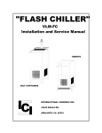
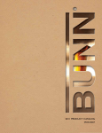
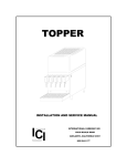
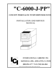
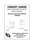
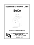
DROP-IN
142015
201415
222021
232321
INSTALLATION AND SERVICE MANUAL
IC
I
INTERNATIONAL CARBONIC INC.
16630 Koala Rd.
Adelanto, California 92301
800 854-1177
5/01
IMPORTANT:
This manual is a guide for installing, operating,
servicing and maintaining this equipment.
Refer to Table of Contents
for page location of detailed information to answer questions that
arise during installation, operating, service and maintenance, or
installation of this equipment.
TABLE OF CONTENTS
PAGE
PREFACE .............................................................................1
GENERAL DESCRIPTION ....................................................2
Location of Soda Fast and Ice Cooled Equipment.................2
Carbonator and Connecting Water Supply ............................2
Drop-In Soda Lines to Carbonator.........................................2
Drop-In Still Drink Lines.........................................................2
Non-Carb ...............................................................................3
Drop-In Syrup lines................................................................3
Installing Drain.......................................................................3
Electrical Connection.............................................................3
Illumination ............................................................................3
TRB .......................................................................................3
Installing High Pressure Regulator ........................................4
Installing Low Pressure Regulator .........................................4
Carbonator and Connecting Water Supply ............................4
Priming Pump ........................................................................4
Testing for Leaks ...................................................................4
Loose – Shipped Parts ..........................................................5
Possible Installation...............................................................5
Possible Installation, Back Room ..........................................6
Brix Instructions .....................................................................7
Proper Brixing Procedures ....................................................8
Sanitizing Procedures............................................................9
Trouble Shooting ...................................................................10 - 12
Drop-In Exploded View..........................................................13
Drop-In Exploded View Breakdown .......................................14
142015 Dimensional and Plumbing Layout ...........................15
201415 Dimensional and Plumbing Layout ...........................16
222021 Dimensional and Plumbing Layout ...........................17
232321 Dimensional and Plumbing Layout ...........................18
Notes .....................................................................................19
PREFACE
INTERNATIONAL CARBONIC INC. has enjoyed over 53 years of
manufacturing excellence in the field of carbonation and in the beverage
related industry. We have had a long and proud history with quality as our
standard and innovation as our goal. Originally started just after World
War II in Canfield, Ohio as Carbonic Dispensers. We enjoyed patents on
the first Sodajet type carbonator.
This method of carbonation
instantaneously carbonated the water to 100% saturation. We developed
the first patented dispensing valve to dispense bulk beverage with
carbonation equal to or in excess of bottled beverages. A valve with three
flavors and soda was another first. We were the first to incorporate the
total postmix package, i.e., carbonation, refrigeration, and the ability to
dispense from one self contained unit. We have pioneered many such
firsts and will continue to develop advanced systems for the future, such
as electronic interrogatable portion controls to electronic liquid level
controls.
We hope you enjoy this piece of equipment that has been produced to
give many years of trouble free service. We thank you for your purchase
and hope we may serve you in the future.
1
INSTALLATION PROCEDURES
GENERAL DESCRIPTION
Upon receiving unit, immediately uncrate and inspect for shipping damage.
ALL DROP-IN’S ARE SHIPPED WITH 3” SHIPPING LEGS. THESE MAY BE
REMOVED AFTER INSTALLATION ALTHOUGH IT IS RECOMMENDED THAT THESE
REMAIN IN PLACE IN CASE OF UNIT REMOVAL FROM INSTALLATION SIGHT. THE
DROP-IN UNIT IS EQUIPPED WITH STAINLESS STEEL INLET LINES THAT ARE
LOCATED ON THE BOTTOM OF THE DROP-IN. BE SURE NOT TO BEND THESE
LINES DURING INSTALLATION, IF BENT OR CRIMPED UNIT COULD BECOME
INOPERABLE.
WARNING: Before shipping or relocating a DROP-IN into a freezing
ambient environment empty plain and carbonated water. Syrup systems
should be flushed and water drained from ice bin. A freezing ambient
environment will cause existing water in unit to freeze possibly resulting
in damage to syrup coils, water coil, ice bin, valve(s), etc.
At this time make sure all parts are also included with shipment, i.e., high pressure
regulator, low pressure regulator, legs, etc.
If shipping damage has occurred,
immediately notify transit agency that transported equipment. If parts are missing, notify
factory.
Location of Soda Fast and Ice Cooled Equipment:
Prior to locating drop-in in its permanent position mark and cut hole position.
following hole sizes should be cut to accommodate the following:
Model
232321
222021
142015
201415
The
Hole size
23 1/2” X 23 1/2”
22 3/4” X 20 3/4”
14 3/4” X 20 3/4”
20 3/4” x 14 3/4”
After hole is cut and prior to installing drop-in into hole use RTV as a sealant around
perimeter of hole. Ice bin must be sealed to counter. Some or all of the following
connections may be made prior to installing the drop-in in the counter.
The five (5) connections to be made are as follows: Drop-in soda line (s) to carbonator,
still drink line (s) to water (Optional), syrup lines to syrup containers or pumps, drain to
drain outlet, and electrical to proper source.
Carbonator and Connection Water Supply: See SODA FAST CARBONATOR
Instruction/Installation Procedure.
Drop-In Soda Lines to Carbonator: Connect lines marked SODA to soda outlet on
carbonator.
Drop-In Still Drink Lines: Marked WATER (Optional) should be connected to incoming
water source. Note: If connected on pressure side of water pump a water regulator must
be installed. After WATER line is made but prior to connection line should be flushed to
eliminate any debris.
2
Non-Carb: Marked NON-CARB and is syrup line that is dedicated to line marked
WATER.
Drop-In Syrup Lines: 1, 2, 3 etc. must be connected to B.I.B. quick coupler for later
connection to B.I.B. pumps at outlet side of box or connected to outlet quick disconnect
for use on transfer tank.
Installing Drain:
DROP-IN’S ARE EQUIPPED WITH THE FOLLOWING DRAINS:
232321
222021
142015
201415
1” PVC NPT
3/4” PVC NPT
1/2” PVC NPT
1/2” PVC NPT
PLEASE USE CAUTION WHEN TIGHTENING FITTING TO COLD PLATE.
NOTE: Do not reduce drain connection from cabinet outlet. Be sure all
connections are watertight.
Electrical Connection:
All units must be wired in accordance with N.E.C. or local city ordinance.
Drop-In units have electrical wire (s) extending from the base of the cabinet, which are
marked 24 volt. This wire (s) will be connected to 24-volt transformer (s). The
transformer supplied for carbonated systems will be 24 volt, 40 VA. When two 24-volt
wires are routed through the drop-in the number of valves exceed the amount
recommended for voltage draw on one transformer. The transformer voltage used for
Juice applications will be 24 volt, 40 VA.
Illumination: When drop-in units are supplied with illumination (Optional), a lamp cord with
plug will extend from the base of the drop-in. The S-980 illuminated merchandiser is 115
volt.
The drop-in unit is equipped with a door interlock switch for the dispensing
heads.
National Sanitation Foundation requires the door be closed during the dispensing
of beverages.
TRB: Transfer Receptacle Box, see illustration.
This optional part can be supplied and can be
Made as a TRB-2 or TRB-4, the numeral 2 or
4 indicating the number of outlets required.
TRB-2
Ice Bin Capacity:
Drop-In Units:
201415
142015
222021
232321
40LBS
40LBS
80LBS
100LBS
3
Installing High Pressure Regulator:
Install CO2 high pressure regulator (furnished with Soda Fast unit) on carbon dioxide gas
cylinder, always making certain a good washer is used in the connection, and tighten
securely so there is no leakage at this connection. Replace regulator anytime it should
continue to creep above the desired pressure setting. Connect 1/4” tubing from outlet of
gas regulator on CO2 tank for later connection to low-pressure gas regulator assembly.
Installing Low Pressure Regulator:
Install low pressure on bulkhead, B.I.B. rack, or location of choice. Connect 1/4” tubing
from high-pressure regulator to incoming port on low-pressure regulator. Fabricate
necessary lines to connect to syrup boxes or tanks. Connect it and adjust low-pressure
regulator. Normal settings for transfer tanks average 10 to 40 p.s.i.
Carbonator and Connecting Water Supply:
See SODA FAST CARBONATOR
Instruction/Installation Procedure. This step must be accomplished prior to proceeding.
Priming Pump:
1.
2.
3.
4.
5.
6.
7.
8.
Turn on water supply.
Open valve on CO2 tank.
Turn on electrical power.
Turn high-pressure regulator screw clockwise until the pressure is adjusted
to 90 to 100 p.s.i.
Actuate each valve by depressing push lever, push button, etc. until all
trapped air is relieved.
Manually depress valve-actuating arm until
carbonator is activated and carbonated water is being dispensed.
Permit carbonator to run until it automatically shuts off. Pump is now fully
primed and carbonator is ready for use.
Ice down drop-in cold plate, do not use sub-cooled ice.
Drop-in unit is now ready for adjustment on water flow. Prior to connecting
syrup to individual valves adjust all valves for standard or fast flow water
adjustments, see brixing instructions.
Testing for Leaks:
Completely back off adjusting screw on low-pressure regulator.
Close valve on top of CO2 cylinder.
Wait for 5 minutes or more. If pressure on high-pressure gauge decreases excessively,
there is a leak in the carbonator circuit.
All connections including cylinder valve should be coated with soapsuds. If bubbles
appear a leak is apparent.
Always be sure that the low pressure adjusting screw is completely backed off before
testing carbonator circuit for leaks. Otherwise, gas going into the syrup tanks would
cause this high pressure gauge needle to balance with pressure in syrup tanks, which
would be a false indication of a leak in the carbonator circuit.
After it has been determined that there are no leaks in the carbonator circuit, open CO2
cylinder valve and adjust low pressure regulator to 15 p.s.i. Allow enough time for the
syrup tanks to fill completely with gas, (5 minutes or longer).
4
Next, completely back off low-pressure regulator adjusting screw, and if gauge needle of
low-pressure regulator commences to move downward, there is a leak in the lowpressure circuit. Check all connections with soapsuds, paying particular attention to
syrup tank covers, syrup quick disconnects etc. If low pressure gauge needle remains
stationary, there is no leak.
Unpack LOOSE-SHIPPED PARTS. At this time make sure all parts listed are present
and in good condition. If any parts are missing, notify factory.
TABLE 2-1
LOOSE - SHIPPED PARTS
Item
No.
1
2
3
4*
5*
6*
7*
* Optional
Part
No.
S-768-K
----SF
S-101
S-221
S-105
Name
Installation/Service Manual
Keys
I.D. Labels
Carbonator
High Pressure CO2 Regulator
Low Pressure CO2 Regulator
6’ Gas Line (Inner Braid)
Qty
1
2
1per flavor
1
1
1
1
1/2" WATER LINE
INDIVIDUAL GATE VALVE
(1/2") RECOMMENDED.
WATER FILTER RECOMMENDED
120 VAC
SYRUP LINES TO BACK ROOM
FLOOR DRAIN
FIGURE 2-1. SAMPLE OF POSSIBLE INSTALLATION.
5
BIBPJ-FJ
S-121
BIB JUICE PUMP, FLOJET
REGULATOR, L.P., SINGLE PORT
PRODUCT OUT
PRODUCT IN
GAS OUT
GAS IN
BIBR2
RACK FOR BIB PUMPS 2 WIDE
RACK INCLINED X 4
S-1086
STEPLESS CLAMP FOR 1/4"
S-144
CROSS, 1/4" HOSE, S.S.
52 in
TO DISPENSER
S-1087
STEPLESS CLAMP
FOR 3/8"
20 in
27 in
S-101
HIGH PRESSURE REGULATOR
QCD
BIB CONNECTOR, LIQUIBOX
S-143
TEE, 1/4" HOSE, S.S.
CO2 CAN BE REPLACED WITH
MECHANICAL AIR PUMP.
INTERNATIONAL CARBONIC INC.
3/8ST
3/8" PLASTIC SYRUP TUBING
1/4IBT
1/4" PLASTIC TUBING,
INNER BRAIDED
3/8IBT
3/8" PLASTIC SYRUP TUBING,
INNER BRAIDED
NOTE: ADD 6 INCHES TO SIDE DIMENSION
WHEN INSTALLING B.I.B. PUMPS TO ONE
SIDE. ADD 12 INCHES TO SIDE DIMENSION
WHEN INSTALLING B.I.B. ON BOTH SIDES.
ICI
ADELANTO, CALIFORNIA
FIGURE 2-1. SAMPLE OF POSSIBLE INSTALLATION BACK ROOM
6
TITLE
POSSIBLE BIB RACK
SET UP
DATE
DRN. BY
CHK. BY
APPR. BY
11/24/98
GLW
BRIX INSTRUCTIONS
1.
Make sure carbonator/water flow is in an operating condition, i.e., high-pressure regulators
set, water and power on and refrigeration in a ready to go mode. In the case of juice systems make sure
water flow is un-restricted. It is also recommended that a water pressure regulator be utilized on all
systems. Water bath systems must have an ice bank formed.
2.
Adjust water flow to 6 ounces in 5 seconds.
3.
Remove nozzle (twist and pull down), then insert syrup separator through nozzle, be it “S”
type or plastic tube, and on ¼” plastic syrup outlet located inside hidden nozzle area. Then press nozzle
back in position.
4.
Actuate valve until syrup separator is full of syrup. Hold brix cup close enough to valve outlet
to form “S” on the flexible plastic tube so as to prevent any water following the flexible tube into syrup
section. This formed “S” will also hold syrup in tube for a more reliable brix reading.
5.
Actuate valve allowing the soda water to flow into large section of cup and syrup into smaller
section. Adjust the syrup metering pin/flow-control as necessary to secure a proper brix. When proper
brix syrup adjustments have been made, the two sections of the cup should fill to the desired ration.
7
Brix Instructions Continued
BRIXING PFC-II VALVE
The water and syrup flows are individually adjusted by their respective metering pin or flow-controls.
Located under the valve cover on the top rear of the valve, see illustration.
One recommended method utilizes the ratio brix cup. The brix cup is divided into two sections, one
to hold up to 9 parts water and the smaller section to hold one or two parts of syrup. When
adjusting a flavor with a ratio of more than 9 to 1 syrup 2 line must be used. When using syrup 2
line the waterside is doubled to 18 to 1 vs. 9 to 1.
When facing the valve, the syrup is always to the right and the water/soda is to the left. To
decrease syrup or water flow, turn metering pin clockwise. To decrease syrup or water flow, when
using flow control valves turn counter-clockwise. To increase, reverse rotation respectively.
The ultimate goal is to achieve a proper ratio of water vs. syrup. This ratio can and will vary with
differing products.
TOP VIEW
(valve cover removed)
18 PARTS/WATER
SYRUP
DECREASE
INCREASE
SYRUP 1
WATER METERING PIN
SYRUP 2
SYRUP METERING PIN
18 to 1 Brix Cup
Maintenance:
Cleaning your valve is recommended to insure a constant quality drink. If a valve is not sanitized on
a regular basis (nightly recommended), the possibility of foamy and off-tasting drinks is greatly
increased.
1.
Turn off key switch normally located on valve plate or side of cabinet. Or disconnect tower
from electrical supply.
2. Clean all exposed areas of valve with mild soap or sanitizing solution and warm water.
3.
Remove nozzle and place in warm water. Do not soak nozzle in bleach water, this will turn
the nozzle yellow and cause deterioration. It is recommended to use a soft bristle brush, part No.
S-1064, to clean any hard to get areas of valve or nozzle. Do not soak nozzle in extremely hot
water, nozzle will warp.
8
SANITIZING PROCEDURES
Your local health department rules and general area cleanliness should determine the frequency at which
the unit should be sanitized.
EQUIPMENT REQUIRED:
1.
2.
3.
4.
5.
Stainless Steel containers (product tanks), or large volume container.
CO2 Supply if applicable (Same as used with dispensing unit).
Cleaning Agent.
Sanitizing Solution.
Phenolphthalein.
NOTE: One recommended cleaning agent and sanitizing agent is manufactured by:
MT. HOOD CHEMICAL CORP.
4444 N.W. Yeon Avenue
Portland, Oregon 97210
Trade names are: STAR - CHLORINATED CLEANER
CROWN - 12.5% SODIUM HYPOCHLORITE BLEACH
Use STAR at 18 oz. per 1 gallon of water yields 2% Sodium Hydroxide Solution.
Use Crown at 2 ounce per 9 gallons of water (gives 200 PPM of available chlorine) at a minimum contact
time of 10 minutes.
1. Disconnect syrup containers and remove product from tubing by purging with carbon dioxide or
flushing with warm water.
2. Visually inspect valve by removing nozzle and inspecting nozzle and valve cavity. Clean nozzle with
cleaning agent, then sanitizing solution, then with potable water. Inspect valve cavity and if dirty
clean with soft bristle brush. Clean exteriors of valve with a soft clothe and warm water. Replace
valve nozzle then go to step #3.
3. Fill syrup lines with a caustic-based (low sudsing, non-perfumed, and rinsed) detergent solution,
(STAR). The solution should be prepared in accordance with the manufacturers recommendations,
but should be at least 2 percent sodium hydroxide. Make sure the syrup lines are completely filled
and allow standing for at least 10 minutes.
4. Flush the detergent solution from the syrup lines with clean water. Continue rinsing until testing with
phenolphthalein shows that the rinse water is free of residual detergent.
5. Fill the syrup lines with a low PH (7.0) chloride solution containing maximum 200-PPM chlorine.
Make sure that lines are completely filled and allow standing for 30 minutes.
6. Reconnect syrup containers and ready Unit for operation.
7. Draw drinks to refill syrup lines and flush the chloride solution from the dispenser.
8. Taste the beverage to verify that there is no off taste.
NOTE: WHEN SANITIZING A TWO FLAVOR VALVE BOTH SYRUPS SHOULD BE FLUSHED
SIMUTAINEOUSLY, BOTH SYRUPS SHOULD BE CLEANED, (DETERGENT SOLUTION),
SIMUTAINEOUSLY, BOTH SYRUPS SHOULD BE FLUSHED UNTIL FREE OF DETERGENT
SIMUTAINEOUSLY AND BOTH SYRUPS SHOULD BE SANITIZED SIMUTAINEOUSLY.
Cold plate systems:
Keep the ice bin clean and the cold plate free of mineral build up. The interval for cleaning will
vary depending on your water conditions. If cold plates are not allowed to drain freely the system
will loose efficiency.
9
TROUBLE SHOOTING
IMPORTANT: Only qualified personnel should service the DROP IN unit and components.
WARNING: To avoid personal injury and or property damage, always disconnect electrical power, shut off
plain water and CO2 supplies before starting any repairs. If repairs are to be made to the carbonated water
system, bleed carbonated water system pressure before proceeding. If repairs are to be made to syrup
system, remove quick disconnects from syrup tanks, or remove QCD from BIB, then bleed system pressure
before proceeding.
CARBONATOR
Trouble
Probable Cause
Remedy
DISPENSING VALVES
Water or syrup
1. Foreign debris under plunger seat
leaking from
or bent, creased stem.
nozzle after
actuation
No water, no
syrup being
dispensed from
valve
No syrup being
dispensed
1.
No electrical power.
1.
2.
3.
4.
5.
6.
1.
2.
3.
4.
Frozen water bath.
Pinched or crimped lines.
Broken sub-miniature switch.
Bad transformer.
Disconnected wire.
Syrup container empty.
Syrup lines crimped.
CO2 cylinder empty.
QCD of syrup installed incorrectly.
Low-pressure regulator defective
or plugged.
Syrup disconnect not attached
correctly.
Loose electrical connection of
syrup solenoid and or open
electrical connection.
Frozen water bath.
2.
3.
4.
5.
6.
1.
2.
3.
4.
a. Disconnect syrup or water from
affected valve.
b. Relieve pressure by activating valve.
c. Remove E-623 nut from syrup or
water solenoid.
d. Remove e-525 coil assembly from e527 stem.
e. Remove E-527 stem from valve
body.
Note: care should be
taken not to dent smooth E-527 wall.
f. Valve stem seat should be inspected
for any foreign debris. If debris is
found remove at this time, also
check E-730 stem. Movement
should be unrestricted and free.
g. Inspect E-730 plunger seat for
damage, replace if damaged.
h. Reassemble by reversing above
procedure.
Plug power cord into electrical box.
Check line voltage.
See “Frozen water bath”.
Repair defective line.
Replace defective switch.
Replace defective transformer.
Attach disconnected wire.
Replenish syrup supply.
Straighten syrup lines.
Change CO2 cylinder.
Re-install QCD correctly.
5.
Repair or replace low-pressure regulator.
6.
Lubricate and attach.
7.
Tighten connection and/or repair open
circuit. Check proper voltage.
8.
See “Frozen Water Bath”.
5.
6.
7.
8.
10
1.
No water being
dispensed
1.
1.
2.
3.
Plain water inlet supply shutoff
closed.
Water filter fouled/clogged.
Pinched or crimped line.
Loose electrical connection, 24
volt.
Water pump motor worn out or
damaged.
Water pump worn out or
damaged.
Frozen water bath.
High-pressure regulator out of
adjustment.
CO2 cylinder empty.
Water, oil, or dirt in C02 supply.
5.
Open plain water inlet supply line shut off
valve.
Replace filter or cartridge.
Repair defective line.
Tighten connection and or repair open
circuit.
Replace motor.
6.
Replace water pump.
7.
1.
4.
See “Frozen water bath”.
Adjust high-pressure regulator as
instructed.
Replace CO2 cylinder.
Clean contaminated CO2 system, (lines,
regulator, etc.) and sanitize as
instructed.
See refrigeration/machine specifications
vs. volume requirements.
Adjust high-pressure regulator as
instructed.
Remove syrup tank quick disconnects.
Relieve pressure; shake tank vigorously,
as necessary to remove overcarbonation.
Clean contaminated nozzle and sanitize
as instructed.
See refrigeration/machine specifications
vs. volume requirements.
4.
Temperature above quality limits.
4.
1.
Pressure of CO2 to high.
1.
2.
Syrup over-carbonated with CO2.
2.
3.
Dirty nozzle and valve cavity.
3.
4.
Temperature above quality limits.
Dispensed
product comes
out clear but
foams in cup or
class
1.
Oil film or soap scum in cup or
glass.
Ice used for finished drink is
subcooled.
1.
Use clean cups and glasses.
2.
1.
Syrup flow regulator not properly
adjusted.
1.
2.
CO2 gas pressure in syrup tanks
insufficient.
Syrup tubing I.D. Insufficient.
2.
Do not use ice directly from freezer.
Allow ice to become “wet” before using.
Note; crushed ice also causes foaming
of beverage. Carbonation is released on
sharp edges of the ice.
Adjust water-to-syrup ratio (see
dispensing station installation
instructions.
Adjust low-pressure regulator as
instructed.
Increase syrup tubing I.D. Note: see
“Brix instructions”
Water-to-syrup
ratio to low or
too high
2.
3.
4.
5.
6.
Volumes of
CO2 to low in
finished product
Dispensed
product makes
foam as it
leaves
dispensing
valve
7.
1.
2.
3.
11
2.
3.
4.
2.
3.
3.
Adjustment of
syrup metering
pin does not
produce desired
water-to-syrup
ratio
1.
2.
3.
4.
5.
6.
No syrup supply.
Syrup tank quick disconnects not
secure.
Low-pressure CO2 regulator out
of adjustment.
B.I.B. QCD disconnected or
improperly installed.
Syrup line restricted.
Dirty or inoperative metering pin
or piston in syrup flow control.
12
1.
2.
Replenish syrup supply as instructed.
Secure quick disconnects.
3.
Adjust low-pressure CO2 regulator as
instructed.
Connect B.I.B. disconnect securely.
4.
5.
6.
Clear restriction or replace restricted line.
Disassemble and clean syrup flow
control. Adjust water-to-syrup ratio, see
“Brix instruction”.
2
1
3
4
1
5
6
8
7
10
9
11
12
13
14
15
8
16
18
19
17
INTERNATIONAL CARBONIC INC.
ICI
ADELANTO, CALIFORNIA
13
TITLE
DROP-IN
DATE
DRN. BY
12/15/98
GLW
CHK. BY
APPR. BY
201415
142015
14
S-865
S-868
S-870
S-677
S-837
S-889
S-854
S-838
S-839
PART NO.
S-980
S-869
S-867
S-768
S-859
S-858
PFC-II
A-20
S-1161
A-59
PART NO.
S-980
S-886
S-884
S-768
S-859
S-885
PFC-II-QR
A-20
S-1164
A-26
S-887
S-883
S-882
S-677
S-863
S-889
S-854
S-864
S-888
PART NO.
S-980
S-862
S-857
S-768
S-859
S-858
PFC-II-QR
A-20
S-1164
A-26
S-852
S-860
S-856
S-677
S-855
S-889
S-854
S-853
S-844
222021
SYM QTY PART NO.
1
1
S-980
2
1
S-877
3
1
S-874
4
1
S-768
5
1
S-859
6
1
S-875
7
PFC-II-QR
8
3
A-20
9
1
S-1161
10
2
A-59
10
2
S-872
11
1
12
1
S-876
13
1
S-873
14 1 SET
S-677
15
1
S-842
16
1
S-889
17 1 SET
S-854
18
2
S-834
19
1
S-839
DESCRIPTION
ILLUMINATED MERCHANDISER, COMPLETE
ANTI SPLASH, CUP REST
RISER ASSY. W/ CM BACK
SWITCH LOCK
DOOR SWITCH ASSY
VALVE MOUNTING PLATE
PFC-II VALVE W/QUICK RELEASE (QR NOT AVAILABLE W/201415)
SCREW, 8-32 X 3/8, PHILLIPS, TH, S.S.
PLASTIC DRAIN ASSY., ELBOW
SCREW, 10-24 X 1/2 HEX CAP, S.S.
SCREW, 1/4-20 X 1/2 HEX CAP, S.S.
DOOR
PICTURE FRAME
WRAPPER, BUCKET, COLD PLATE, & PICTURE FRAME ASSY.
LEG, 3", SET OF 4
SLEEVE
HOLD DOWN BRACKET FOR SODA FAST CARBONATOR
LEG, 6", S.S, SET OF 4
SERVICE PANEL, FRONT & REAR
DRAIN ASSY. FOR SLEEVE
DROP-IN
232321
5 3/4
142015
6
15 3/8
3
18 5/8
9 1/2
3 1/4
12
C
L
3
20 1/4
16
SODA WATER
S5
S4
S3
S2
S1
SODA WATER
S5
S4
S3
S2
S1
IN
13
OUT
BACK VIEW
15 1/4
CL
14 1/4
15
5 3/4
201415
6
S-1
S-2
S-3
S-4
S-5
S-6
15 3/8
3
9 1/2
18 5/8
SODA WATER
3 1/4
12
C
L
FRONT VIEW
3
14 1/4
18
16
REAR VIEW CABINET BASE
S-6
S-5
S-4
S-3
S-2
S-1
SODA WATER
15 1/4
C
L
20 1/4
16
222021
5 3/4
6
S-1
S-2
S-3
S-4
S-5
S-6
S-7
S-8
15 3/8
3
SODA WATER
FRONT VIEW
20 1/4
18
16
REAR VIEW CABINET BASE
SODA WATER
18 1/4
C
L
20 1/4
17
S-8
S-7
S-6
S-5
S-4
S-3
S-2
S-1
232321
5 3/4
6
15 3/8
4
18 5/8
9 1/2
S-4
S-5
S-6
S-7
S-8
SODA WATER
S-3
S-2
S-1
NON-CARBONATED
3 1/4
18
FRONT VIEW
3
12 1/2
10 1/2
23
22
16
REAR VIEW CABINET BASE
15 3/8
S-8
S-7
SODA WATER
S-6
S-3
S-5
S-4
NON-CARBONATED
S-1
S-2
21 1/4
C
L
2/10/99
23
18
NOTE SECTION
Frequently Called Numbers:
__________________________________
____________________________
__________________________________
____________________________
__________________________________
____________________________
__________________________________
____________________________
__________________________________
____________________________
__________________________________
____________________________
CO2 SETTINGS:
High Pressure ________________________ PSI
Low Pressure ________________________ PSI
Product Setup:
#1
#2
_____________________________________
__________________________________
_____________________________________________________________________________________________
_____________________________________________________________________________________________
_____________________________________________________________________________________________
_____________________________________________________________________________________________
_____________________________________________________________________________________________
___________________________________________________
_____________________________________________________________________________________________
_____________________________________________________________________________________________
_____________________________________________________________________________________________
_____________________________________________________________________________________________
_____________________________________________________________________________________________
___________________________________________________
11/05
19