1
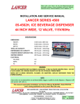
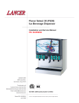
Please refer to the Lancer web site (www.lancercorp.com) for
information relating to Lancer Installation and Service Manuals,
Instruction Sheets, Technical Bulletins, Service Bulletins, etc.
INSTALLATION AND SERVICE MANUAL
FOR
30 INCH WIDE LANCER
ICE COOLED DISPENSER
(23308)
SPECIFICATIONS
DIMENSION
Width (without rim)
Depth (without rim)
Height (without legs or fittings)
30 inches
23 inches
18 inches
Height (with legs)
23 inches
WEIGHT
(762 mm)
(584 mm)
(457 mm)
(Below counter)
(584 mm)
(Below counter)
Drop-In
Shipping
Empty
Operating
300 pounds
240 pounds
370 pounds
(136.37 kg)
(109.10 kg)
(168.18 kg)
ICE BIN CAPACITY
130 pounds
( 59.09 kg)
INLET FITTINGS
3/8 inches
(9.525 mm) barb
DRINK CAPACITY
The unit will deliver at least fifteen (15) - 12 ounce, or at least seven (7) - 24 ounce, drinks per minute
under 40ºF (4.4ºC) in a 75ºF (23.9ºC) ambient environment as long as the cold plate is covered with ice.
This manual supersedes Installation And Service Manual 28-0225/02, dated 11/05/97,
and is ONLY being published on the Lancer web site.
6655 LANCER BLVD. • SAN ANTONIO, TEXAS 78219 USA • (210) 310-7000
FAX SALES
• NORTH AMERICA – 210-310-7245 • INTERNATIONAL SALES – 210-310-7242 • CUSTOMER SERVICE – 210-310-7242 •
• LATIN AMERICA – 210-310-7245 • EUROPE – 32-2-755-2399 • PACIFIC – 61-8-8268-1978 •
FAX Engineering: • 210-310-7096
"Lancer" is the registered trademark of Lancer • Copyright — 2006 by Lancer, all rights reserved
REV:
07/28/06
P.N. 28–0225/03
TABLE OF CONTENTS
SPECIFICATIONS ...................................................................................................................................COVER
TABLE OF CONTENTS ......................................................................................................................................i
1. INSTALLATION ...........................................................................................................................................1
1.1 RECEIVING........................................................................................................................................1
1.2 UNPACKING ......................................................................................................................................1
1.3 SELECTING A COUNTER LOCATION ..............................................................................................1
1.4 WATER SUPPLY ................................................................................................................................1
1.5 ELECTRICAL SUPPLY ......................................................................................................................1
1.6 SYRUP CONTAINERS.......................................................................................................................1
1.7 INSTALLATION OF THE UNIT...........................................................................................................2
1.8 CONNECTION OF THE UNIT ...........................................................................................................2
1.9 START-UP ..........................................................................................................................................3
1.10 ADJUSTING WATER FLOW ..............................................................................................................3
1.11 ADJUSTING WATER-TO-SYRUP RATIO (BRIX) ..............................................................................4
1.12 REPLENISHING SYRUP SUPPLY (5 GALLON TANKS) ..................................................................4
2. RECOMMENDED SERVICE AND MAINTENANCE ...................................................................................4
2.1 SCHEDULED .....................................................................................................................................4
2.2 CLEANING AND SANITIZING SYSTEMS .........................................................................................4
2.3 CLEANING AND SANITIZING FIGAL SYSTEMS..............................................................................5
2.4 CLEANING AND SANITIZING BAG-IN-BOX (BIB) SYSTEMS .........................................................7
2.5 VALVES ..............................................................................................................................................7
2.6 ICE BIN COMPARTMENT ON ALL ICE CHESTS .............................................................................7
3. TROUBLE SHOOTING................................................................................................................................8
3.1 NO CARBONATION ...........................................................................................................................8
3.2 NOISY CARBONATOR PUMP...........................................................................................................8
3.3 OFF TASTE IN SODA ........................................................................................................................8
3.4 VALVES INOPERABLE ......................................................................................................................8
4. ILLUSTRATIONS, PARTS LISTINGS, AND WIRING DIAGRAMS ............................................................9
4.1 LANCER ICE COOLED DISPENSER - ACCESSORIES ..................................................................9
4.2 LANCER ICE COOLED DISPENSER - SERIES 23308 DROP-IN.............................................10-11
4.3 ICE COOLED UNIVERSAL WIRING DIAGRAM WITH BIN LID SWITCH ......................................12
4.4 ICE COOLED UNIVERSAL WIRING DIAGRAM WITHOUT BIN LID SWITCH...............................13
i
1. INSTALLATION
1.1
RECEIVING
Each unit is completely tested under operating conditions and thoroughly inspected before
shipment. At the time of shipment, the carrier accepts the unit, and any claim for damage must be
made with the carrier. Upon receiving units from the delivering carrier, carefully inspect carton for
visible indication(s) of damage. If damage exists, have carrier note the same on the bill of lading
and file a claim with the carrier.
1.2
UNPACKING
A.
B.
C.
D.
1.3
The Lancer Ice Cooled Dispenser is shipped in a corrugated shipping carton.
Using proper lifting techniques, carefully remove the unit from the corrugated shipping carton.
Remove parts from the Ice Compartment.
Inspect unit for concealed damage(s). If evident, notify delivering carrier and file a claim against
same.
SELECTING A COUNTER LOCATION
A. Select a counter location which is close to a properly grounded electrical outlet, and a water
supply that meets the requirements specified in Section 1.4 below.
B. Counter location must be able to safely support a minimum of 400 pounds (181.8 kg) after the
counter cutout is made.
1.4
WATER SUPPLY
CAUTION
FAILURE TO LIMIT WATER PRESSURE TO 50 PSI WILL RESULT IN IMPROPER
PERFORMANCE OF THE DISPENSER.
A. An adequate potable water supply must be provided. The water supply line must be at least a
3/8 inch pipe with a minimum of 20 PSI line pressure, but not exceeding a maximum of 50 PSI.
Water pressure exceeding 50 PSI must be reduced to 50 PSI with a pressure regulator.
CAUTION
A FILTER IN THE WATER LINE MUST BE USED IF THE WATER SUPPLY CONTAINS ANY
APPRECIABLE AMOUNT OF SILT, SAND, OR ANY OTHER DEBRIS. FAILURE TO DO SO CAN
RESULT IN EQUIPMENT DAMAGE.
B. The Carbonator Pump is equipped with a Strainer and a Tee on the outlet side for a plain water
Valve (if required), but a water supply containing any appreciable quantity of silt, fine sand, or
other debris requires a Filter ahead of the Unit. The Filter cartridge must be cleaned
periodically, depending upon the condition of the water. Failure to do so may starve the Pump
and cause it to burn out; thereby, voiding the equipment warranty
1.5
ELECTRICAL SUPPLY
WARNING
THE POWER SUPPLY MUST BE PROPERLY ELECTRICALLY GROUNDED TO AVOID
POSSIBLE ELECTRICAL SHOCK OR SERIOUS INJURY TO THE OPERATOR. THE POWER
CORD IS PROVIDED WITH A THREE PRONG GROUNDED PLUG. IF A THREE-HOLE
GROUNDED ELECTRICAL OUTLET IS NOT AVAILABLE, USE AN APPROVED METHOD TO
GROUND THE UNIT.
A. A standard 15 AMP, 110 VAC, 60 Hz, single phase electrical power outlet with a ground
connector should be provided for the operation of the unit
1.6
SYRUP CONTAINERS
A. When the unit is used in the Coca-Cola Company installations, the syrup containers are to be
attached as outlined in the appropriate Coca-Cola Company Service Manual.
B. For other installations, the syrup containers (sold as an accessory) are of stainless steel
construction with a capacity of five gallons. They are equipped with a CO2 gas quick disconnect
fitting and a syrup quick disconnect fitting. The standard syrup outlet is a 1/4 inch (6.35 mm)
1
male flare (MF). A low pressure regulator manifold (an accessory) may be mounted on the wall
above the syrup tanks.
C. The inlets on the unit, located on the right rear of the machine, are tagged (or coded) to the
proper valves. When making the connection to these inlets, provide a good, leak tight joint to
prevent twisting the tubing.
1.7
INSTALLATION OF THE UNIT
A
Inspect the counter location where the unit is to be installed. Verify that the counter is strong
enough to safely support a 400 pound load, after the cutout for the unit is made.
B. Verify that the unit will fit in the desired location. See Figure 1 for the footprint and counter cutout
for the unit.
NOTE
Remember that the unit extends 23 inches (584 mm) below the counter, including the shipping
risers, which Lancer recommends be left attached to the unit. Should the dispenser ever require
removal, the shipping risers will protect the inlet tubes from being damaged.
C. After the counter cutout is complete, the unit may be dropped into the counter.
D. When the unit is properly located in the counter, the rim MUST be sealed to the counter using
an approved silicone sealant. THIS STEP IS IMPERATIVE!
(CUTOUT)
30 1/4" (768 mm)
Solid lines
represent counter
cutout dimensions.
(CUTOUT)
23 1/4"
(591 mm)
25"
(635 mm)
Dashed lines
represent the counter
footprint of the ice
bin flange.
32" (813 mm)
FRONT
(View Looking Down)
1.8
Counter Cutout for Dispenser
Figure 1
CONNECTION OF THE UNIT
A. Position the CO2 gas tank in the desired location. Assemble the high pressure regulator to the
CO2 gas tank and run jumper line to low pressure regulator.
B. Attach the CO2 gas line to the carbonator by attaching the line from the high pressure regulator
to the single check valve marked ‘gas’ on top of the Carbonator Tank. The setting of the high
pressure CO2 gas Regulator should be 90 PSI to 110 PSI.
CAUTION
DO NOT TURN ON THE CO2 SUPPLY AT THIS TIME.
C. Position the syrup tanks in the desired location. Attach the CO2 gas lines leading from the low
pressure regulator to these tanks.
D. Connect syrup lines from tanks to the appropriate inlets at the right front of the unit. The syrup
inlets are identified.
CAUTION
A FILTER IN THE WATER LINE MUST BE USED IF THE WATER SUPPLY CONTAINS ANY
APPRECIABLE AMOUNT OF SILT, SAND, OR ANY OTHER DEBRIS. FAILURE TO DO SO CAN
RESULT IN EQUIPMENT DAMAGE.
E. Mount the water filter assembly (if required) and water regulator (if required) in a convenient
location.
2
CAUTION
FAILURE TO LIMIT WATER PRESSURE TO 50 PSI WILL RESULT IN IMPROPER
PERFORMANCE OF THE DISPENSER.
F.
Connect the water inlet line to the water regulator (if required), water filter (if required), and then
to the water inlet of the carbonator pump on the carbonator.
G. Provide a suitable drain in the plumbing system and attach the one (1) inch (2.54 cm) diameter
schedule 40 PVC drains to the drain. The drip pan drainage outlet is located at the center rear
of the unit. The ice water drainage outlet is located at the right front of the unit
H. Be sure to place the ice trap in the drain outlet inside the ice bin before filling the cabinet with
ice. This device holds the ice away from the drain outlet, allowing the ice water to drain
properly.
WARNING
THE POWER SUPPLY MUST BE PROPERLY ELECTRICALLY GROUNDED TO AVOID
POSSIBLE ELECTRICAL SHOCK OR SERIOUS INJURY TO THE OPERATOR. THE POWER
CORD IS PROVIDED WITH A THREE PRONG GROUNDED PLUG. IF A THREE-HOLE
GROUNDED ELECTRICAL OUTLET IS NOT AVAILABLE, USE AN APPROVED METHOD TO
GROUND THE UNIT.
I.
1.9
Plug in the transformer box to a standard 15 AMP, 110 VAC, single phase outlet. The unit will
internally convert 110 VAC electricity to 24 VAC.
START UP
A. After all connections to water, CO2 gas, electrical power, and syrup containers are made, check
for leaks.
B. Check to insure that syrup tanks contain syrup.
CAUTION
DO NOT OPERATE CARBONATOR PUMP WITH WATER SUPPLY SHUT OFF.
C. Turn water ON. Open the pressure relief valve on the carbonator tank by lifting the wire ring,
and hold it open until water flows from the relief valve. Close the relief valve and turn on the
CO2 gas and electrical power in that order.
D. To fill all lines with water, cycle the carbonator
I.D. PANEL
several times by operating the dispersing
(Shown in
open position)
valves.
1. A low pressure gas regulator controls the
flow of syrup to each dispensing valve.
For proper operation of the valves, the
pressure regulator should be set so that
25 to 35 PSI is at the back block of the
valve.
2 For diet type syrup, the tank pressures
should be set at 10 PSI, or as
recommended by the syrup supplier.
Additional pressure may be necessary,
depending on the distance from the syrup
tank to the unit.
E. Fill unit with ice cubes to the level of the door
opening at this time.
COVER SCREW
FLOW CONTROL
WATER
FLOW CONTROL
SYRUP
Increase Decrease
Increase Decrease
NOZZLE (WITH
DIFFUSER INSIDE)
1.10 ADJUSTING WATER FLOW
A
The water flow can be adjusted to either 1.25
ounces/second (37 ml/sec) or 2.50
ounces/second (74 ml/sec) on all dispensing
valves by using the following procedure.
B. The unit should have ice on the cold plate for
3
Valve Adjustments
Figure 2
C.
D.
E.
F.
G.
H.
I.
J.
at least one hour before attempting to BRIX the valves. The drink temperature should be no
higher than 40ºF (4.4ºC) when the ratio is set. This is done after the unit has ice in the ice bin.
Slide the ID panel UP until the flow controls are exposed (see Figure 2).
Remove the nozzle by turning the nozzle counter clockwise and pulling down.
Remove the diffuser by pulling the diffuser in a downward motion.
Install the Lancer (yellow) syrup separator (PN 54-0031) in place of the nozzle.
Activate dispensing valve to fill the separator syrup tube.
Hold a Lancer BRIX cup (PN 05-0090) under the syrup separator and dispense water and syrup
into the BRIX cup for four (4) seconds. Divide the number of ounces (ml) of water in the cup by
four (4) to determine the water flow rate per second.
To obtain the proper flow, use a screwdriver to adjust water flow control (see Figure 2).
Repeat this process for each valve.
1.11 ADJUSTING WATER-TO-SYRUP RATIO (BRIX)
A.
B.
C.
D.
E.
F.
Hold the Lancer ratio cup under the syrup separator and activate valve. Check ratio (BRIX).
To obtain the proper ratio, use screw-driver to adjust syrup flow control (see Figure 2).
Remove syrup separator.
Install diffuser and nozzle.
Slide ID panel DOWN.
Repeat this process for each valve.
NOTE
In all cases of re-assembly of valves involving o-rings, be sure the o-ring is lubricated with water
or an FDA approved lubricant to prevent leakage or damage to the o-ring.
1.12 REPLENISHING SYRUP SUPPLY (5 GALLON TANKS)
A. The following procedure should be used to add syrup to a tank after the system is in operation.
1 Shut off CO2 gas supply system to syrup tanks.
2. Snap off the self-sealing quick-coupler. Allow gas in the syrup tank to escape by pulling the
outer shell of the quick-coupler toward the flexible line and allowing the whole connection to
pull free.
WARNING
TO AVOID POSSIBLE PERSONAL INJURY OR PROPERTY DAMAGE, DO NOT ATTEMPT
TO REMOVE SYRUP TANK COVER UNTIL CO2 PRESSURE HAS BEEN RELEASED FROM
TANK.
3.
4.
5.
6.
Remove the cover by pulling upward on the hinged locking bar.
Fill tank with appropriate syrup, leaving one (1) inch (2.54 cm) of space for CO2 gas.
Replace locking cover insuring that the cover and cover gasket are properly aligned.
Snap on quick-coupler and lock it securely in place. Turn CO2 gas pressure ON. When
properly connected, the gas will automatically enter the tank with an audible noise.
2. RECOMMENDED SERVICE AND MAINTENANCE
2.1
SCHEDULED
A. Daily – See Section 2.5 for daily cleaning.
B Monthly – See Section 2.6 for monthly cleaning.
C. Periodic Sanitizing - See sections 2.2, 2.3, and 2.4 for sanitizing requirements.
2.2
CLEANING AND SANITIZING SYSTEMS
A. General Information
NOTE
The cleaning and sanitizing procedures provided herein pertain to the Lancer equipment
identified by this manual. If other equipment is being cleaned, follow the guidelines established
for that equipment.
(1) Lancer equipment (new or reconditioned) is shipped from the factory cleaned and sanitized
4
in accordance with NSF guidelines. The operator of the equipment must provide
continuous maintenance as required by this manual and/or state and local health
department guidelines to ensure proper operation and sanitation requirements are
maintained.
(2) Cleaning and sanitizing should be accomplished only by trained personnel. Sanitary gloves
are to be used during cleaning and sanitizing operations. Applicable safety precautions
must be observed. Instruction warnings on the product being used must be followed.
IMPORTANT
Water lines are not to be disconnected during the cleaning and sanitizing of syrup lines to
avoid contamination.
(3) Recommended Preparation of Cleaning Solutions.
(a) Cleaning solutions (for example, Ivory Liquid, Calgon, etc.) mixed with clean, potable
water at a temperature of 90 to 110 degrees Fahrenheit should be used to clean
equipment. The mixture ratio, using Ivory Liquid, is one (1) ounce of cleanser to two (2)
gallons of water. A minimum of four (4) gallons of cleaning mixture should be prepared.
NOTE
Extended lengths of product lines may require that an additional volume of solution be
prepared.
(b) Any equivalent cleanser may be used as long as it provides a caustic based,
non-perfumed, easily rinsed mixture containing at least two (2) percent sodium
hydroxide (NaOH).
(4) Recommended Preparation of Sanitizing Solutions.
(a) Sanitizing solutions should be prepared in accordance with the manufacturer’s written
recommendations and safety guidelines. For example, mix Diversol CX in clean,
potable water at a temperature of 90 to 110 degrees Fahrenheit so that the solution
provides 200 parts per million (PPM) available chlorine. A minimum of four (4) gallons
of sanitizing solution should be prepared.
NOTE
Extended lengths of product lines may require that an additional volume of solution be
prepared.
(b) Any equivalent sanitizing solution may be used as long as it is prepared in accordance
with the manufacturer’s written recommendations and safety guidelines, and provides
200 parts per million (PPM) available chlorine.
2.3
CLEANING AND SANITIZING FIGAL SYSTEMS
A. Remove all ice from ice bin by melting with hot water.
B. Remove quick disconnect from syrup tank.
CAUTION
DO NOT USE A WIRE BRUSH TO CLEAN VALVES.
C. Using a clean plastic bristle brush and a detergent soap solution prepared in accordance with
the instructions in Section 2.2, scrub both valves of the disconnect. Rinse with clean, potable
water.
D. Using a mechanical spray bottle and a sanitizing solution prepared in accordance with the
instructions in Section 2.2, spray both halves of the quick disconnects. Allow to air dry.
NOTE
Please note that a fresh water rinse cannot follow sanitization of equipment. Purge only with the
end use product. This is an NSF requirement.
E. Connect syrup line to a syrup tank filled with clean, potable, room temperature water. Connect
CO2 supply hose to tank and pressurize.
F. Place waste container under applicable dispensing valve. Activate valve until water is
dispensed. Flush and rinse line and fittings for a minimum of 60 seconds to remove all traces
5
of residual product.
NOTE
Extended lengths of product lines may require additional time for flushing and rinsing lines.
WARNING
TO AVOID POSSIBLE PERSONAL INJURY OR PROPERTY DAMAGE, DO NOT ATTEMPT
TO REMOVE SYRUP TANK COVER UNTIL CO2 PRESSURE HAS BEEN RELEASED FROM
TANK.
G. Disconnect CO2 supply hose from the water filled syrup tank.
H. Prepare cleaning solution as described in Section 2.1 above. Fill a tank with cleaning solution.
Connect syrup line to the tank. Connect CO2 supply hose to tank and pressurize.
I. Place waste container under applicable dispensing valve. Activate valve and draw cleaning
solution through lines for a minimum of 60 seconds. This will ensure line is flushed and filled
with cleaning solution. Allow line to stand for at least 30 minutes.
NOTE
Extended lengths of product lines may require additional time for flushing and filling lines.
J. Disconnect CO2 supply hose from the tank.
K. Connect syrup line to a tank filled with clean, potable, water at a temperature of 90º to 110ºF.
Connect CO2 supply hose to tank and pressurize.
L. Place waste container under applicable dispensing valve. Activate valve to flush and rinse line
and fittings for a minimum of 60 seconds to remove all traces of cleaning solution. Continue
rinsing until testing with phenolpthalein shows that the rinse water is free of residual detergent.
M. Disconnect CO2 supply hose from the tank.
N. Fill a tank with sanitizing solution. Connect syrup line to the tank. Connect CO2 supply hose to
tank and pressurize.
O. Remove dispensing valve nozzle (twist and pull down) and pull out center mixing baffle. Using
a plastic bristle brush and detergent soap solution scrub the nozzle, mixing baffle, bottom of
dispensing valve, and cup lever. Rinse with clean water.
P. Reassemble mixing baffle and nozzle.
Q. Place waste container under applicable dispensing valve. Activate valve and draw sanitizing
solution through line for a minimum of 60 seconds. This will ensure line is flushed and filled with
sanitizing solution. Allow line to stand for at least 30 minutes.
R. Disconnect CO2 supply hose from the tank.
S. Reconnect syrup lines to syrup containers (for example, quick disconnects, figal containers, etc.)
and ready unit for operation.
WARNING
FLUSH SANITIZING SOLUTION FROM SYRUP SYSTEMS AS INSTRUCTED.
SANITIZING SOLUTION LEFT IN SYSTEM COULD CREATE HEALTH HAZARD.
T.
RESIDUAL
Draw drinks and refill lines with end product to flush sanitizing solution from the dispenser.
NOTE
Please note that a fresh water rinse cannot follow sanitization of equipment. Purge only with the
end use product. This is an NSF requirement.
U. Test dispenser in normal manner for proper operation. Taste dispensed product to ensure there
is no off-taste. If off-taste is found, additional flushing of syrup system may be required.
V. Repeat cleaning, rinsing, and sanitizing procedures for each valve/syrup circuit.
W. Clean exterior of unit as instructed in Section 2.6.
X. Using a spray bottle of sanitizing solution, spray the underside of all dispenser valves, valve
spouts and cup levers. Allow to air dry.
NOTE
Thoroughly rinse inside and outside of syrup tank that was used for sanitizing solution with plain
water to remove all solution residue.
Y. Fill ice bin with ice. Install ice bin cover on unit.
6
2.4
CLEANING AND SANITIZING BAG-IN-BOX (BIB) SYSTEMS
A. Disconnect syrup quick disconnect coupling from syrup packages and connect coupling to a bag
valve removed from an empty Bag-in-Box package.
B. Place end of syrup inlet line, with bag valve attached, in a clean container filled with clean,
potable, room temperature water.
C. Place waste container under applicable dispensing valve. Activate valve until water is
dispensed. Flush and rinse line and fittings for a minimum of 60 seconds to remove all traces
of residual product.
NOTE
Extended lengths of product lines may require additional time for flushing and rinsing lines.
D. Prepare cleaning solution as described in Section 2.2 above. Place end of syrup inlet line in
container filled with cleaning solution.
E. Place waste container under applicable dispensing valve. Activate valve and draw cleaning
solution through lines for a minimum of 60 seconds. This will ensure line is flushed and filled
with cleaning solution. Allow line to stand for at least 30 minutes.
F. Place end of syrup inlet line in a clean container filled with clean, potable, water at a
temperature of 90º to 110oF.
G. Place waste container under applicable dispensing valve. Activate valve to flush and rinse line
and fittings for a minimum of 60 seconds to remove all traces of cleaning solution. Continue
rinsing until testing with phenolpthalein shows that the rinse water is free of residual detergent.
H. Prepare sanitizing solution as described in Section 2.2 above. Place end of syrup inlet line in
container filled with sanitizing solution which has been prepared.
I. Activate valve and draw sanitizing solution through line for a minimum of 60 seconds. This will
ensure line is flushed and filled with sanitizing solution. Allow line to stand for at least
30 minutes.
J. Remove bag valve from quick disconnect coupling and reconnect syrup inlet line to syrup
package. Ready unit for operation.
WARNING
FLUSH SANITIZING SOLUTION FROM SYRUP SYSTEMS AS INSTRUCTED.
SANITIZING SOLUTION LEFT IN SYSTEM COULD CREATE HEALTH HAZARD.
RESIDUAL
K. Draw drinks and refill lines with end product to flush sanitizing solution from the dispenser.
NOTE
Please note that a fresh water rinse cannot follow sanitization of equipment. Purge only with the
end use product. This is an NSF requirement.
L. Test dispenser in normal manner for proper operation. Taste dispensed product to ensure there
is no off-taste. If off-taste is found, additional flushing of syrup system may be required.
M. Repeat cleaning, rinsing, and sanitizing procedures for each valve circuit.
2.5
VALVES
A. Valves may be cleaned and sanitized (see preparation in Section 2.2) in the same manner.
1. Remove cover and disconnect power so the valve will not be activated during the cleaning
procedure. Remove nozzle and diffuser. Wash these parts in cleaning solution; then
immerse them in a bath of sanitizing solution for 15 minutes.
2. Visually inspect around nozzle area for syrup residue. This area may be cleaned with warm
water and cloth or with the nozzle brush supplied. Wipe off dispensing lever.
3. Wearing sanitary gloves, remove, drain and air dry the nozzle and diffuser.
4. Wearing sanitary gloves, replace diffuser, twist nozzle in place.
5. Connect power and replace cover. Valve is ready for operation.
2.6
ICE BIN COMPARTMENT ON ALL ICE CHESTS
A. The ice bin compartment of the dispenser should be thoroughly cleaned and sanitized at least
once every month. Use. the following procedure.
B. Prepare cleaning solution and sanitizing solution in accordance with Section 2.2.
7
C. Using the cleaning solution and a clean soft cloth, wash down the sides of the ice bin and the
surface of the aluminum casting.
D. Using clean, potable water, thoroughly rinse away the cleaning solution from the sides and
surface of the casting.
E. Using plastic sanitary gloves, soak a white cotton gauze cleaning rag in the sanitizing solution
and wipe all surfaces in the ice compartment.
NOTE
Please note that a fresh water rinse cannot follow sanitization of equipment. Purge only with the
end use product. This is an NSF requirement.
F.
Sanitizing of the ice compartment is complete. Refill with ice.
3. TROUBLESHOOTING
CAUSE
TROUBLE
3.1
No carbonation.
REMEDY
A. Carbonator motor not running.
B. Absence of CO2 gas.
C. Gas only from valves.
D. Carbonator tank air bound.
E. CO2 gas pressure below
90 PSI.
F.
3.2
Noisy Carbonator
Pump.
Carbonator motor running
continuously.
A. Check power supply. Be sure
toggle switch is in ON position.
B. Replace with full tank of CO2 gas.
C. Check for power failure. Check
fuses. Clean strainer on pump.
D. Relieve gas pressure in tank by
pulling ring on safety relief valve
until water spurts out.
E. Reset high pressure CO2 gas
regulator to 90-110 PSI. Change
CO2 tank if required.
F. Check switch on carbonator.
Checkwater in check valve for
blockage. Check carbonator
control. Check carbonator pump
for efficiency.
A. Insufficient water supply or
water leak, allowing air to be
pulled into pump.
B. Loose pump coupling.
A. Provide adequate water supply.
Check strainer for Cleanliness.
B. Tighten set screw on pump
coupling.
3.3
Off taste in soda.
A. Leaking water check valve,
allowing carbonated water to
back into supply line.
A. Dismantle and clean check valve.
Replace O-Ring, if torn or distorted.
3.4
Valves inoperable.
A. Loss of power.
A. Check power supply to see if
plugged in. Check transformer
circuit breaker. Check main power
circuit breaker, 110V.
NOTES:
8
4. ILLUSTRATIONS, PARTS LISTINGS, AND WIRING DIAGRAMS
4.1
LANCER ICE COOLED DISPENSER -- ACCESSORIES
Illuminated Marquee
PN 85-2303
Splash Guards Kit
PN 82-2077
Water Spigot for Ambient
Temperature Water Kit
PN 82-3801
9
4.2
LANCER ICE COOLED DISPENSER - SERIES 23308 DROP-IN
17
11
9
8
18
19
7
16
15
14
10
12
13
5
6
1
3
4
20
2
10
4.2
LANCER ICE COOLED DISPENSER - SERIES 23308 DROP-IN (CONTINUED)
ITEM
PART NO.
DESCRIPTION
R 1
R 2
R 3
4
R 5
R -R -R 6
R 7
R 8
R 9
R 10
R 11
R 12
R 13
R 14
42-0045
51-5152/01
51-5803/01
04-0072
30-6041/03
82-2948
04-0289
51-6135
04-1262
48-1026/02
52-2397
12-0097
51-5150/01
13-0005
11-0015
04-1089
R
R
R
R
R
R
R
R
R
R
R
R
R
R
05-1092
23-1001/01
30-5926
30-5982
04-0148
82-3029
82-2119
81-0126
23-0862
05-2467
51-6119
07-0360/01
07-0555/01
07-0556/01
Tank Assy
Tank Wrapper
Rim Assy
Rivet
Ice Bin Lid
Shipping Riser
Screw
Tower Body Assy
Screw, 1/4 X 20
Foamed Manifold
Wire Harness Assy
Key Lock Switch
Faucet Plate
Strain Relief Bushing
Socket Housing
Screw, 10 - 32 x 1.00,
Back Block
Drip Tray Assy
Cup Rest
Splash Plate
Tower Cap
Screw
Power Supply Assy
Kit, Sliding Door, Bin Switch
Keys
Drain Spider
Drain Seal, Drip Tray
Ice Barrier Plate
Hole Plug, Tower Cap
Hole Plug, Faucet Plate
Hole Plug, Upper Tower
Body
Hole Plug, Keyswitch
15
16
17
18
19
20
---------
R --
07-0405
R in margin indicates revision or change
11
12
Y
3M
3F
2M
2F
: FEMALE BLADE RECEPTACLE
: MALE BLADE
: 2 PIN FEMALE CONNECTOR
: 2 PIN MALE CONNECTOR
: 3 PIN FEMALE CONNECTOR
: 3 PIN MALE CONNECTOR
: "Y" CONNECTOR (2 MALES, 1 FEMALE)
F
Y
2F
ALTERNATE
POWER SUPPLY
F
M
2M
2F
WHITE
2F
2M
WHITE
BLACK
BLACK
WHITE
WHITE
F
F
2M
Y
Y
F
2F
F
PCB
KEY
LOCK
WHITE
BLACK
2M
F
F
BLACK
ORIGINAL
POWER SUPPLY
WATER SPIGOT
SOLENOID
WHITE
BLACK
2F
CDA
SOLENOID
BLACK
M
2F
2M
M
F
M
2F
2M
WHITE
BLACK
BLACK
6
THIS HARNESS IS NOT USED
IN CONJUNCTION WITH
ALTERNATE POWER SUPPLY
WHITE
WHITE
F
2F
PRESSURE SWITCH
5
MARQUEE
OR
MERCHANDISER
2F
3F
4
F
2F
3M
SYRUP OUT
LIGHT KIT
3
VALVE MANIFOLD HARNESS
2F
2M
F
2
F
F
1
BIN
SWITCH
2F
REPLACES INTERNAL
CHERRY SWITCH HARNESS
ON SPRITE VALVE
F
F
WHITE
F
WATER SPIGOT
BUTTON
ICE COOLED UNIVERSAL
WIRING DIAGRAM WITH BIN LID SWITCH
4.3
ICE COOLED UNIVERSAL WIRING DIAGRAM WITH BIN LID SWITCH
13
2F
Y
3M
3F
2M
: FEMALE BLADE RECEPTACLE
: MALE BLADE
: 2 PIN FEMALE CONNECTOR
: 2 PIN MALE CONNECTOR
: 3 PIN FEMALE CONNECTOR
: 3 PIN MALE CONNECTOR
: "Y" CONNECTOR (2 MALES, 1 FEMALE)
F
2F
2M
2F
ALTERNATE
POWER SUPPLY
F
M
2M
2F
WHITE
WHITE
2F
2M
2F
2M
BLACK
BLACK
WHITE
WHITE
F
F
2M
Y
Y
F
BLACK
2F
F
PCB
KEY
LOCK
WHITE
BLACK
PRESSURE SWITCH
6
Y
M
BLACK
WHITE
2F
3F
5
F
2F
3M
SYRUP OUT
LIGHT KIT
2M
WHITE
BLACK
F
F
BLACK
ORIGINAL
POWER SUPPLY
WATER SPIGOT
SOLENOID
2F
CDA
SOLENOID
BLACK
M
2F
VALVE MANIFOLD HARNESS
2F
2M
F
2 3 4
THIS HARNESS IS NOT USED
IN CONJUNCTION WITH
ALTERNATE POWER SUPPLY
F
1
MARQUEE
OR
MERCHANDISER
2F
REPLACES INTERNAL
CHERRY SWITCH HARNESS
ON SPRITE VALVE
F
F
WHITE
F
WATER SPIGOT
BUTTON
ICE COOLED UNIVERSAL
WIRING DIAGRAM WITHOUT BIN LID SWITCH
4.4
ICE COOLED UNIVERSAL WIRING DIAGRAM WITHOUT BIN LID SWITCH
NOTES
Please refer to the Lancer web site (www.lancercorp.com) for
information relating to Lancer Installation and Service Manuals,
Instruction Sheets, Technical Bulletins, Service Bulletins, etc.
14