1
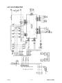
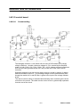
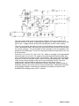
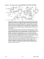
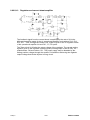
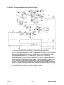
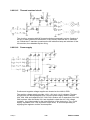
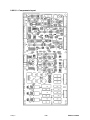
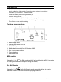
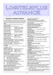
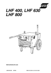
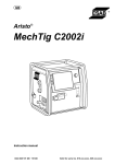
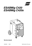
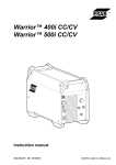
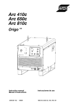
LHF 405 PIPEMASTER
Service manual
0349 300 057
071024
Valid for serial no. 522--xxx--xxxx
READ THIS FIRST . . . . . . . . . . . . . . . . . . . . . . . . . . . . . . . . . . . . . . . . . . . . . . . . . . . . . . . . . . . . . . . . .
INTRODUCTION . . . . . . . . . . . . . . . . . . . . . . . . . . . . . . . . . . . . . . . . . . . . . . . . . . . . . . . . . . . . . . . . . . .
TECHNICAL DATA . . . . . . . . . . . . . . . . . . . . . . . . . . . . . . . . . . . . . . . . . . . . . . . . . . . . . . . . . . . . . . . . .
WIRING DIAGRAM . . . . . . . . . . . . . . . . . . . . . . . . . . . . . . . . . . . . . . . . . . . . . . . . . . . . . . . . . . . . . . . . .
Component description . . . . . . . . . . . . . . . . . . . . . . . . . . . . . . . . . . . . . . . . . . . . . . . . . . . . . . . . . .
LHF 405 PIPEMASTER . . . . . . . . . . . . . . . . . . . . . . . . . . . . . . . . . . . . . . . . . . . . . . . . . . . . . . . . . . .
DESCRIPTION OF OPERATION . . . . . . . . . . . . . . . . . . . . . . . . . . . . . . . . . . . . . . . . . . . . . . . . . . . . .
LH21/0 control board . . . . . . . . . . . . . . . . . . . . . . . . . . . . . . . . . . . . . . . . . . . . . . . . . . . . . . . . . . . .
LH21/0:1 Current setting . . . . . . . . . . . . . . . . . . . . . . . . . . . . . . . . . . . . . . . . . . . . . . . . . . . . . . . . .
LH21/0:2 Functional control circuit ANTISTICK, HOTSTART, ARCFORCE . . . . . . . . . . . . . .
LH21/0:3 Regulator and current shunt amplifier . . . . . . . . . . . . . . . . . . . . . . . . . . . . . . . . . . . . . .
LH21/0:4 Synchronisation and thyristors firing . . . . . . . . . . . . . . . . . . . . . . . . . . . . . . . . . . . . . . .
LH21/0:5 Thermal overload circuit . . . . . . . . . . . . . . . . . . . . . . . . . . . . . . . . . . . . . . . . . . . . . . . . .
LH21/0:6 Power supply . . . . . . . . . . . . . . . . . . . . . . . . . . . . . . . . . . . . . . . . . . . . . . . . . . . . . . . . . . .
LH21/0 -- Components layout . . . . . . . . . . . . . . . . . . . . . . . . . . . . . . . . . . . . . . . . . . . . . . . . . . . . . .
CHECKING AND CALIBRATION PROCEDURES . . . . . . . . . . . . . . . . . . . . . . . . . . . . . . . . . . . . . .
SERVICE INSTRUCTIONS . . . . . . . . . . . . . . . . . . . . . . . . . . . . . . . . . . . . . . . . . . . . . . . . . . . . . . . . . .
What is ESD? . . . . . . . . . . . . . . . . . . . . . . . . . . . . . . . . . . . . . . . . . . . . . . . . . . . . . . . . . . . . . . . . . . .
Thermal switch (thermostat) replacement procedure . . . . . . . . . . . . . . . . . . . . . . . . . . . . . . .
INSTRUCTIONS . . . . . . . . . . . . . . . . . . . . . . . . . . . . . . . . . . . . . . . . . . . . . . . . . . . . . . . . . . . . . . . . . . .
SAFETY . . . . . . . . . . . . . . . . . . . . . . . . . . . . . . . . . . . . . . . . . . . . . . . . . . . . . . . . . . . . . . . . . . . . . . . .
INSTALLATION . . . . . . . . . . . . . . . . . . . . . . . . . . . . . . . . . . . . . . . . . . . . . . . . . . . . . . . . . . . . . . . . . . . .
Connecting to mains . . . . . . . . . . . . . . . . . . . . . . . . . . . . . . . . . . . . . . . . . . . . . . . . . . . . . . . . . . . .
OPERATION . . . . . . . . . . . . . . . . . . . . . . . . . . . . . . . . . . . . . . . . . . . . . . . . . . . . . . . . . . . . . . . . . . . . . . .
Controls and connections . . . . . . . . . . . . . . . . . . . . . . . . . . . . . . . . . . . . . . . . . . . . . . . . . . . . . . .
MMA welding . . . . . . . . . . . . . . . . . . . . . . . . . . . . . . . . . . . . . . . . . . . . . . . . . . . . . . . . . . . . . . . . . . .
Arc Air Gouging . . . . . . . . . . . . . . . . . . . . . . . . . . . . . . . . . . . . . . . . . . . . . . . . . . . . . . . . . . . . . . . . .
Overheating protection . . . . . . . . . . . . . . . . . . . . . . . . . . . . . . . . . . . . . . . . . . . . . . . . . . . . . . . . . .
MAINTENANCE . . . . . . . . . . . . . . . . . . . . . . . . . . . . . . . . . . . . . . . . . . . . . . . . . . . . . . . . . . . . . . . . . . . .
ORDERING OF SPARE PARTS . . . . . . . . . . . . . . . . . . . . . . . . . . . . . . . . . . . . . . . . . . . . . . . . . . . . . .
NOTES . . . . . . . . . . . . . . . . . . . . . . . . . . . . . . . . . . . . . . . . . . . . . . . . . . . . . . . . . . . . . . . . . . . . . . . . . . .
TOCe
-- 2 --
3
3
4
5
5
7
8
8
8
10
11
12
13
13
15
16
18
18
18
19
19
20
20
21
21
21
21
22
22
22
23
READ THIS FIRST
Maintenance and repair work should be performed by an experienced person, and
electrical work only by a trained electrician. Use only recommended replacement parts.
This service manual is intended for use by technicians with electrical/electronic training for
help in connection with fault--tracing and repair.
Use the wiring diagram as a form of index for the description of operation. The circuit
board is divided into numbered blocks, which are described individually in more detail in
the description of operation. All component names in the wiring diagram are listed in the
component description.
This manual contains details of all design changes that have been made up to and
including October 2007.
The LHF 405 PIPEMASTER is designed and tested in accordance with international
and European standard IEC/EN 60974--1.
On completion of service or repair work, it is the responsibility of the person(s) etc.
performing the work to ensure that the product does not depart from the requirements
of the above standard.
INTRODUCTION
LHF 405 PIPEMASTER is thyristor controlled welding rectifier designed for welding
with coated electrodes and arc air gouging.
The welding rectifiers can be used with the following remote control devices:
AT1, AT1 Coarse Fine.
Do not dispose of electrical equipment together with normal waste!
In observance of European Directive 2002/96/EC on Waste Electrical and Electronic
Equipment and its implementation in accordance with national law, electrical equipment
that has reached the end of its life must be collected separately and returned to an
environmentally compatible recycling facility. As the owner of the equipment, you should
get information on approved collection systems from our local representative.
By applying this European Directive you will improve the environment and human health!
smlhfpm1
-- 3 --
Edition 071024
TECHNICAL DATA
LHF 405 PIPEMASTER
Maximum load
35 % duty cycle
60 % duty cycle
100 % duty cycle
Setting range
Open circuit volt.
Open circuit output
at 400 V
Power factor
(max current)
Efficiency
(max current)
Enclosure class
Application class
Weight
Dimens. lxwxh
400 A/36 V
310 A/33 V
240 A/30 V
10A/20V--400A/36V
75 V
330 W
0,80
70 %
IP 23
194 kg
915/515/630
Duty cycle
The duty cycle refers to the time as a percentage of a ten--minute period that you can weld at a certain load without overloading.
Enclosure class
The IP code indicates the enclosure class, i. e. the degree of protection against penetration by solid
objects or water. Equipment marked IP23 is designed for indoor and outdoor use.
Application class
The symbol
indicates that the power source is designed for use in areas with increased
electrical hazard.
smlhfpm1
-- 4 --
Edition 071024
WIRING DIAGRAM
Component description
WARNING !
STATIC ELECTRICITY can damage circuit
boards and electronic components.
ESD
S
Observe precautions for handling electrostatic
sensitive devices.
S
Use proper static--proof bags and boxes.
B1
Thermal switch: breaks at 68_C, resets at 59_C; fitted on the thyristor
heatsink
B2
Thermal switch: breaks at 160_C
C1
Capacitor 2µF, for cooling fan
C2,C3
Capacitor 0,1µF
H1
Indicating lamp, white
H2
LED, yellow; on when thermal overload is activated, i.e. when one or both
of thermal switcjes B1 and B2 are open
L
Inductor
LH21/0
Circuit board
M1
Fan
Q01
Mains switch
R01
Potentiometer 2kΩ, for controling the welding current
R03
Potentiometer 10kΩ, for ARC FORCE
R1
Base current resistor, 100Ω
RB
Shunt, 120mV@400A
S1
Selector switch, MMA/Air--Arc Gouging
T1
Main transformer
T2
Control transformer, supplied at 35V from X45, secondary 19V supplies
circuit board LH21/0
V1,V3,V5
Main diodes
V2,V4,V6
Main thyristors
smlhfpm1
-- 5 --
Edition 071024
V7
Freewheel diode
V8,V9,V10,
V11,V12,V13
Base current diodes
X01
Contact, 6 pole, male
X02
Remote control socket
X10
Mains terminal block
X20
Terminal block
X40
Terminal block
X45
Terminal block
XF20
Contact, 15 pole, female
XF30
Contact, 9 pole, female
XF40
Contact, 12 pole, female
XK1,XK2
Welding current terminals
XM20
Contact, 15 pole, male
XM30
Contact, 9 pole, male
XM40
Contact, 12 pole, male
smlhfpm1
-- 6 --
Edition 071024
LHF 405 PIPEMASTER
smlhfpm1
-- 7 --
Edition 071024
DESCRIPTION OF OPERATION
LH21/0 control board
LH21/0:1
Current setting
The bandgap reference 1,23V diode V58 on LH21/0 PCB makes up a primary
voltage reference. Another reference voltage 10,7V is created by the amplifier
made of A13b, R132, C51, R131, R130. The +10,7V voltage reference powerises
local current setting potentiometer R01 and provide the for the cable remote
controller.
Switching between local and remote setting source is made by means of analog
switches included in the A17. Local setting voltage from the potentiometer R01,
through the switch A17c and RC filter is given to the input of the voltage follower
A13a.
The remote control setting is activated automatically, after connecting the remote
controller to the socket. The cable remote control circuit is galvanically separated
from the rest of the circuit.
smlhfpm1
-- 8 --
Edition 071024
The optocoupler VC2 carries a signal which switches off the A17c switch, and
switches on the A17d switch, connecting the signal from output of the A12b to the
input of the voltage follower A13a, thus activating the remote control setting.
The VC1 optocoupler transmits a signal of actual welding current setting in a form
of the PWM square wave, with duty cycle proportional to the position of the knob in
the remote controller. The circuit made of the comparator A11a and transistor V54,
generates the PWM signal. The A11b comparator disables the generator if the unit
is disconnected.
Parts VB1, C41, R100, V51, V52, C42, C43 make up a supply for the galvanically
separated part of the circuit. The signal of the stable amplitude and variable duty
cycle is created on the collector of the V55 transistor. This signal is then averaged
by means of the low--pas filter made on the A12a operational amplifier. The range
of the remote setting voltage is then set in the next amplifier A12b. The R121
potentiometer sets null offset at minimum setting of the remote control
potentiometer, and the R125 potentiometer sets the maximum setting voltage at
maximum setting of the of the remote control potentiometer. Calibration procedure
is described in chapter ”Checking and calibration procedures of the LHF 405
PIPEMASTER welding power source” in detail.
smlhfpm1
-- 9 --
Edition 071024
LH21/0:2
Functional control circuit ANTISTICK, HOTSTART, ARCFORCE
The ANTISTICK function is carried out by the circuit made of the A14 IC and the
transistor V56. If the output voltage falls down below the ANTISTICK threshold,
transistor V56 switches on, consequently switches off the output transistor of the
A14a comparator. After delay, defined by values of C55 and R151, the output
transistor of the A14b comparator switches on. It pulls down the current setting
signal on the A16a to the minimum value, and consequently, it causes the limiting
of the output current of the power supply. It works that way in the MMA mode. In
electrogouging mode the ANTISTIC function is disabled by short--circuiting of the
C55 capacitor.
The HOT START function is carried out by the circuit made of the A15 IC and D1.
When the welding starts and the arc is created, the +12V signal shows up on the
non--inverting input of the A15a operational amplifier. The capacitor C60 is charged
via resistors R164,R165,R166 (or the potentiometer of the HOT START time
setting). Time required for charging the C60 to +10,7V is the time of the HOT
START. If the voltage on the C60 remains less then 10,7V, there is a high level on
the A15b output, and the output transistor of the D1b, connects resistor R147 to
the ground. It causes the approximately 30% voltage rise on the A16a operational
amplifier’s output, and the adequate rise of the current setting value.
The ARC FORCE function is carried out by the circuit made of the A16 operational
amplifier. From the moment of crossing the ARC FORCE threshold, further
decreasing of the output voltage causes decreasing of the voltage on the A16b
output. Consequently, the voltage on the slider of the R03 potentiometer
decreases, voltage on the A16a output increases, thus increasing the welding
current. The maximum current increase caused by the arc shortening, may be
adjusted by means of the R03.
smlhfpm1
-- 10 --
Edition 071024
LH21/0:3
Regulator and current shunt amplifier
The feedback signal from the current shunt is amplified by the rate of 50 in the
differential amplifier made of the A1 operational amplifier and resistors R12, R13,
R10, R11. Then, through the resistor R14, signal is given to the PI regulator made
of the operational amplifier A2 and R17, C7, C8 parts.
The Zener diode V13 limits the output voltage of the regulator. The current setting
signal is given to the regulator summing point (inverting input of the A2 OA), via
potentiometer R6 and resistor R5 . The power supply may be disabled by the
setting positive voltage through the resistor R16 and thus achieving the regulator
output voltage that blocks thyristor’s firing circuit.
smlhfpm1
-- 11 --
Edition 071024
LH21/0:4
Synchronisation and thyristors firing
The synchronisation circuit consists of synchronised ramp generators,
comparators, and firing pulse forming circuit. Signal from the synchronising winding
goes via R66(53)(40) and diode limiter made V26(23)(20) and V27(24)(21) diodes,
and then through divider R67(54)(41), R68(55)(42) to non--inverted input of the
comparator A5b(A4b)(A3b). The R69(56)(43), R70(57)(44), C34(26)(18),
R71(58)(45) parts connected to the output of this comparator make up
synchronised ramp generator. The amplitude of the ramp is adjusted by means of
the R71(58)(45) potentiometer. Ramp voltage is compared with the output voltage
of the regulator in comparator A5c(A4c)(A3c). Thus the firing phase shift is
created. The signal from the comparator enables the pulse generator A8(A7)(A6).
Generator output controls the output driver made on transistors V8(6)(4), V9(7)(5).
Driver may be disabled by the positive signal on the cathode of the V42(41)(40) ) in
a case of thermal overload or the lack of synchronisation.
smlhfpm1
-- 12 --
Edition 071024
LH21/0:5
Thermal overload circuit
The circuit co--operates with NC thermal switches connected in series. Opening of
the any of them (placed on the transfer or the rectifier) switches the V1 transistor
on. Closed the V1 transistor powerises the H2 indication lamp and switches off the
V2 transistor, thus disables thyristor firing.
LH21/0:6
Power supply
Positive and negative voltage supplies are located on the LH21/0 PCB.
The positive voltage supply provides +25V, +15V and +14,5V voltages. Thyristor
firing drivers are directly supplied from +25V the power supply made of diodes
V34, V36, V38, and capacitors C67, C68, C69. Another set of capacitors C64, C65,
C66 is placed after the diode V33 .and supplied in chain the A9 +15V voltage
regulator. It provides supply for the pulse partition of the electronics. The +14,5V
supply, separated from +15V by means of the diode, is used exceptionally for
supplying the regulator and the shunt amplifier.
smlhfpm1
-- 13 --
Edition 071024
The negative voltage supply consists of the V35, V37, V39 diodes, the C63
capacitor and the --15V negative voltage regulator A10. The --15V supply supplies
operational amplifiers on the LH21/0 PCB, except ones creating shunt amplifier
and the regulator, which are powered from the --14,5V supply, taken after the diode
V31.
smlhfpm1
-- 14 --
Edition 071024
LH21/0 - Components layout
smlhfpm1
-- 15 --
Edition 071024
CHECKING AND CALIBRATION PROCEDURES
1.
Check whether the connection of the power transformer windings is suitable to the
mains supply.
2.
Switch the welder by means of the switch on the front panel. The lamp marked ”I”
should light.
3.
Checking of the ramp amplitudes on the LH21/0 PCB.
Thorough setting of the ramp amplitudes is anticipated as the part of the fabrication
process, on specialised testing post. It is also possible to make it directly in the
machine, for instance during repair or in a case of suspicion that ramps are
discalibrated.
To carry it out:
4.
5.
6.
7.
a.
put the jumper ZW3 on the LH21/0 PCB. Diodes V16, V17 should light with the
same intensity. If not, balance the intensity by means of the potentiometer R45,
b.
remove jumper ZW3, and put in on ZW7; check intensity of light of diodes V16, V17
I; balance intensity, if it’s not balanced,
c.
remove jumper ZW7, and put in on ZW11; check intensity of light of diodes V16,
V17 I; balance intensity, if it’s not balanced. Remove the jumper.
Setting the current range.
a.
set the current setting potentiometer on the maximum,
b.
load the welding power source to achieve approximately 36V,
c.
by means of the potentiometer R6 set the output current equal to 400A @ 36V,
d.
turn down the setting potentiometer to minimum,
e.
load the welding power source to achieve approximately 21V,
f.
by means of the potentiometer R150 set the minimum output current on 25A,
g.
Check the setting of the following values of the output current:
25A@21V;
100A@24V;
200A@28V;
400A@36V.
HOT START checking.
a.
set 100A output current by means of the setting knob,
b.
connect instantly the 0,24Ω load. Observe the output current. It should amount to
130A for 1s. Then it should fall down within another 0,2 s to 100A. Measurements
should be carried out by means of the oscilloscope with memory,
c.
disconnect the load.
ARC FORCE checking.
a.
set 100A output current with the setting knob,
b.
set the ARC FORCE knob to minimum,
c.
gradually load the power source untill output voltage is about 13V; the actual
output current should be 100--103A,
d.
set the ARC FORCE knob to maximum, load the power source to achieve 24V
voltage on output,
e.
gradually increase the load, following the voltage; starting from the threshold of
18,5V -- actual output current should increase; at the 13V on the output, the actual
output current should be 185A.
ANTISTICK checking.
a.
smlhfpm1
set the ARC FORCE knob to minimum,
-- 16 --
Edition 071024
8.
9.
b.
set 100A output current by means of the setting knob in MMA mode,
c.
gradually increase the load, following the voltage; after achieving 5V the actual
output current should be reduced to the level < 32A after 2s delay.
Setting and checking of the cable remote controller.
a.
connect cable remote controller to the socket X02. Remote control should be
activated automatically,
b.
set the knob on the remote controller on minimum,
c.
set the 0,0 V between GND and RMREF (measuring point [11]) by means of the
trimmer R121 on the LH21/0 PCB
d.
set the knob on the remote controller on maximum,
e.
set the +10,7V between GND and RMREF (measuring point [11]) by means of the
trimmer R125 on the LH21/0 PCB,
f.
check the actual current range of the welding power source. If it would be different
from this achieved by local current setting, it may be corrected. Minimum value
could be adjusted be means of R121 trimmer, maximum value by means of R125.
Thermal overload protection checking.
a.
smlhfpm1
break the circuit of thermostats disconnecting one connector on the thermostat
placed on the rectifier. It should be followed by disabling of the welding power
source (no capability of welding). This state should be indicated by the orange
lamp ,marked with ”overtemperature” mark. Closing the circuit should restore
welding capability and switching off the orange indication lamp.
-- 17 --
Edition 071024
SERVICE INSTRUCTIONS
WARNING !
STATIC ELECTRICITY can damage circuit
boards and electronic components.
ESD
S
Observe precautions for handling electrostatic
sensitive devices.
S
Use proper static--proof bags and boxes.
What is ESD?
A sudden transfer or discharge of static electricity from one object to another. ESD stands for
Electrostatic Discharge.
How does ESD damage occur?
ESD can cause damage to sensitive electrical components, but is not dangerous to people.
ESD damage occurs when an ungrounded person or object with a static charge comes into
contact with a component or assembly that is grounded. A rapid discharge can occur,
causing damage. This damage can take the form of immediate failure, but it is more likely
that system performance will be affected and the component will fail prematurely.
How do we prevent ESD damage?
ESD damage can be prevented by awareness. If static electricity is prevented from building
up on you or on anything at your work station, then there cannot be any static discharges.
Nonconductive materials (e.g. fabrics), or insulators (e.g. plastics) generate and hold static
charge, so you should not bring unnecessary nonconductive items into the work area.
It is obviously difficult to avoid all such items, so various means are used to drain off any
static discharge from persons to prevent the risk of ESD damage. This is done by simple
devices: wrist straps, connected to ground, and conductive shoes.
Work surfaces, carts and containers must be conductive and grounded, use only antistatic
packaging materials. Overall, handling of ESD--sensitive devices should be minimized to
prevent damage.
Thermal switch (thermostat) replacement procedure
1.
Spare thermostat must be the same type as replaced one.
2.
Spare thermostat should be mounted within radius of 10mm or less from broken
thermostat. If it’s possible and safe for transformer winding, broken thermostat may be
removed. Then the spare thermostat is to be mounted right in place of broken one.
3.
Spare thermostat should adjoin protected winding as tight as possible.
4.
Spare thermostat must be secured with silicone glue of working temperature of 200oC
or higher.
smlhfpm1
-- 18 --
Edition 071024
INSTRUCTIONS
This chapter is an extract from the instructions for LHF 405 PIPEMASTER.
SAFETY
Users of ESAB welding equipment have the ultimate responsibility for ensuring that anyone who
works on or near the equipment observes all the relevant safety precautions. Safety precautions
must meet the requirements that apply to this type of welding equipment. The following recommendations should be observed in addition to the standard regulations that apply to the workplace.
All work must be carried out by trained personnel well--acquainted with the operation of the welding
equipment. Incorrect operation of the equipment may lead to hazardous situations which can result
in injury to the operator and damage to the equipment.
1.
Anyone who uses the welding equipment must be familiar with:
S its operation
S location of emergency stops
S its function
S relevant safety precautions
S welding
2.
The operator must ensure that:
S no unauthorised person is stationed within the working area of the equipment when it is
started up.
S no--one is unprotected when the arc is struck
3.
The workplace must:
S be suitable for the purpose
S be free from draughts
4.
Personal safety equipment
S Always wear recommended personal safety equipment, such as safety glasses, flame--proof
clothing, safety gloves.
S Do not wear loose--fitting items, such as scarves, bracelets, rings, etc., which could become
trapped or cause burns.
5.
General precautions
S Make sure the return cable is connected securely.
S Work on high voltage equipment may only be carried out by a qualified electrician.
S Appropriate fire extinquishing equipment must be clearly marked and close at hand.
S Lubrication and maintenance must not be carried out on the equipment during operation.
WARNING!
Read and understand the instruction manual
before installing or operating.
smlhfpm2
-- 19 --
Edition 071024
INSTALLATION
The installation must be executed by a professional.
WARNING!
This product is intended for industrial use. In a domestic environment this product may cause radio
interference. It is the user’s responsibility to take adequate precautions.
S
Installation must be carried out by a qualified electrician.
S
Check that the welding rectifier is configured for the available mains supply before
connecting it to the mains.
S
See Connecting to mains for cable rating and fuse rating.
S
Connect the mains cable to the rectifier according to the relevant regulations and install
a suitable fuse in the main fuse box.
S
Make sure the welding rectifier is not covered or positioned so that cooling is
obstructed.
Connecting to mains
LHF 405 PIPEMASTER
LHF 405 PIPEMASTER
Frequency
50/60 Hz
60 Hz
Voltage
Current at
100% duty cycle
230V
460V
44 A
22 A
60% duty cycle
56 A
28 A
35% duty cycle
71 A
36 A
Fuse, slow
65 A
35 A
Cable area (4xmm2)
10
6
NB: The mains cable areas and fuse sizes as shown above are in accordance with Swedish
regulations. They may not be applicable in other countries: make sure that the cable area and fuse
sizes comply with the relevant national regulations.
smlhfpm2
-- 20 --
Edition 071024
OPERATION
S
Select suitable earth and return cables and connect them to the terminals marked +
and -- on the front of the rectifier. Connect the return cable to the work piece.
S
Set switch (1) to position ”I”. The fan will start.
S
Select the welding method using the switch (4).
S
Set the welding current:
S
a.
by means of knob (6) if socket (7) remains unplugged,
b.
by means of knob on remote control unit if plugged in socket (7),
The rectifier is now ready for welding.
Controls and connections
1. Mains supply switch
2. Yellow lamp, thermal cut--out
3. ON/OFF lamp
4. Method selector switch: Arc Air Gouging, MMA
5. Arc Force duration setting
6. Current setting
7. Remote socket
MMA welding
Set switch (4) to
. In MMA mode implicitly “anti stick” function is ON. It prevents
of sticking the electrode to workpiece during arc striking.
Arc Air Gouging
Set switch (4) to
. In Arc Air Gouging mode current should be set close to
maximum value in order to ensure proper gouging conditions.
smlhfpm2
-- 21 --
Edition 071024
Overheating protection
If the internal temperature becomes too high, the welding is interrupted and disabled.
This state is indicated by permanent lighting of the orange indicating lamp on the
front of the unit. It resets automatically when the temperature falls down.
MAINTENANCE
Note!
All guarantee undertakings from the supplier cease to apply if the customer himself
attempts any work in the product during the guarantee period in order to rectify any
faults.
Only those persons who have appropriate electrical knowledge (authorised
personnel) may remove the safety plates to connect or carry out service,
maintenance or repair work on welding equipment.
Cleaning
Check regularly that the power source is free from dirt.
How often, and to what extent, cleaning should be carried out depends on the
welding process, arc time, disposition and the surrounding environment. It will
normally suffice to blow the power source clean using compressed air (reduced
pressure) once a year.
If the power source is very dirty, brushing and vacuuming are recommended.
S
Disconnect the welding power source from the mains current supply.
S
Remove the adapter from the socket. Lock the socket to prevent unauthorised
connection.
At fixed installations, the safety switch should be set to the off position. Lock the
switch.
S
Remove the power source’s safety plates for best access.
After cleaning, all safety plates must be mounted before you connect the power
source to the mains supply.
ORDERING OF SPARE PARTS
Spare parts may be ordered through your nearest ESAB dealer, see the last page of
this publication.
smlhfpm2
-- 22 --
Edition 071024
NOTES
notes
-- 23 --
ESAB subsidiaries and representative offices
Europe
AUSTRIA
ESAB Ges.m.b.H
Vienna--Liesing
Tel: +43 1 888 25 11
Fax: +43 1 888 25 11 85
BELGIUM
S.A. ESAB N.V.
Brussels
Tel: +32 2 745 11 00
Fax: +32 2 745 11 28
THE CZECH REPUBLIC
ESAB VAMBERK s.r.o.
Vamberk
Tel: +420 2 819 40 885
Fax: +420 2 819 40 120
DENMARK
Aktieselskabet ESAB
Herlev
Tel: +45 36 30 01 11
Fax: +45 36 30 40 03
FINLAND
ESAB Oy
Helsinki
Tel: +358 9 547 761
Fax: +358 9 547 77 71
FRANCE
ESAB France S.A.
Cergy Pontoise
Tel: +33 1 30 75 55 00
Fax: +33 1 30 75 55 24
GERMANY
ESAB GmbH
Solingen
Tel: +49 212 298 0
Fax: +49 212 298 218
GREAT BRITAIN
ESAB Group (UK) Ltd
Waltham Cross
Tel: +44 1992 76 85 15
Fax: +44 1992 71 58 03
ESAB Automation Ltd
Andover
Tel: +44 1264 33 22 33
Fax: +44 1264 33 20 74
HUNGARY
ESAB Kft
Budapest
Tel: +36 1 20 44 182
Fax: +36 1 20 44 186
ITALY
ESAB Saldatura S.p.A.
Mesero (Mi)
Tel: +39 02 97 96 81
Fax: +39 02 97 28 91 81
THE NETHERLANDS
ESAB Nederland B.V.
Amersfoort
Tel: +31 33 422 35 55
Fax: +31 33 422 35 44
NORWAY
AS ESAB
Larvik
Tel: +47 33 12 10 00
Fax: +47 33 11 52 03
POLAND
ESAB Sp.zo.o.
Katowice
Tel: +48 32 351 11 00
Fax: +48 32 351 11 20
PORTUGAL
ESAB Lda
Lisbon
Tel: +351 8 310 960
Fax: +351 1 859 1277
SLOVAKIA
ESAB Slovakia s.r.o.
Bratislava
Tel: +421 7 44 88 24 26
Fax: +421 7 44 88 87 41
SPAIN
ESAB Ibérica S.A.
Alcalá de Henares (MADRID)
Tel: +34 91 878 3600
Fax: +34 91 802 3461
SWEDEN
ESAB Sverige AB
Gothenburg
Tel: +46 31 50 95 00
Fax: +46 31 50 92 22
ESAB international AB
Gothenburg
Tel: +46 31 50 90 00
Fax: +46 31 50 93 60
SWITZERLAND
ESAB AG
Dietikon
Tel: +41 1 741 25 25
Fax: +41 1 740 30 55
North and South America
ARGENTINA
CONARCO
Buenos Aires
Tel: +54 11 4 753 4039
Fax: +54 11 4 753 6313
Asia/Pacific
CHINA
Shanghai ESAB A/P
Shanghai
Tel: +86 21 5308 9922
Fax: +86 21 6566 6622
INDIA
ESAB India Ltd
Calcutta
Tel: +91 33 478 45 17
Fax: +91 33 468 18 80
INDONESIA
P.T. ESABindo Pratama
Jakarta
Tel: +62 21 460 0188
Fax: +62 21 461 2929
JAPAN
ESAB Japan
Tokyo
Tel: +81 3 5296 7371
Fax: +81 3 5296 8080
MALAYSIA
ESAB (Malaysia) Snd Bhd
Selangor
Tel: +60 3 8027 9869
Fax: +60 3 8027 4754
SINGAPORE
ESAB Asia/Pacific Pte Ltd
Singapore
Tel: +65 6861 43 22
Fax: +65 6861 31 95
Representative offices
BULGARIA
ESAB Representative Office
Sofia
Tel/Fax: +359 2 974 42 88
EGYPT
ESAB Egypt
Dokki--Cairo
Tel: +20 2 390 96 69
Fax: +20 2 393 32 13
ROMANIA
ESAB Representative Office
Bucharest
Tel/Fax: +40 1 322 36 74
RUSSIA
LLC ESAB
Moscow
Tel: +7 095 543 9281
Fax: +7 095 543 9280
LLC ESAB
St Petersburg
Tel: +7 812 336 7080
Fax: +7 812 336 7060
Distributors
For addresses and phone
numbers to our distributors in
other countries, please visit our
home page
www.esab.com
SOUTH KOREA
ESAB SeAH Corporation
Kyungnam
Tel: +82 55 269 8170
Fax: +82 55 289 8864
UNITED ARAB EMIRATES
ESAB Middle East FZE
Dubai
Tel: +971 4 887 21 11
Fax: +971 4 887 22 63
BRAZIL
ESAB S.A.
Contagem--MG
Tel: +55 31 2191 4333
Fax: +55 31 2191 4440
CANADA
ESAB Group Canada Inc.
Missisauga, Ontario
Tel: +1 905 670 02 20
Fax: +1 905 670 48 79
MEXICO
ESAB Mexico S.A.
Monterrey
Tel: +52 8 350 5959
Fax: +52 8 350 7554
USA
ESAB Welding & Cutting Products
Florence, SC
Tel: +1 843 669 44 11
Fax: +1 843 664 57 48
ESAB AB
SE-- 695 81 LAXÅ
SWEDEN
Phone +46 584 81 000
www.esab.com
070514