1
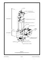
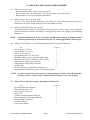
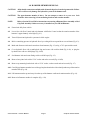
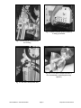
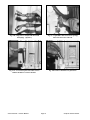
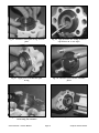
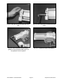
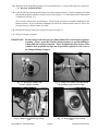
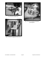
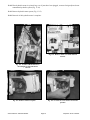
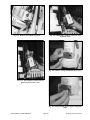
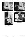
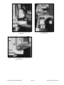
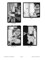
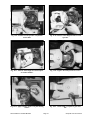
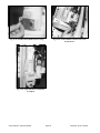
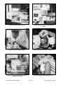
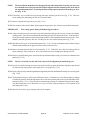
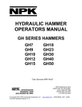
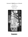
GEOPROBE® GH40 HYDRAULIC HAMMER
SERVICE MANUAL
Technical Bulletin No. 95-040
PREPARED: February, 1995
REVISED: April, 2002
GEOPROBE GH40 HYDRAULIC HAMMER
A DIVISION OF KEJR, INC.
COPYRIGHT© 2002, 2000, 1995 Kejr, Inc.
ALL RIGHTS RESERVED
No part of this publication may be reproducedor transmitted in any form or by any means,
electronic or mechanical, including photocopy, recording,or any information storage
and retrieval system, without permission in writing from Kejr, Inc.
WARRANTY: Geoprobe® Systems warrants its products to be free from defects in materials and workmanship under normal
use and service for a period of one hundred eighty (180) days from the date of delivery to the client. Geoprobe Systems will
repair or replace any product returned to Salina, Kansas, which appears upon inspection by Geoprobe Systems to be defective
in materials or workmanship. Geoprobe Systems shall have no obligation under this warranty for the cost of labor, downtime, transportation charges, or for repair or replacement of any product which has been misused, carelessly handled or
modified or altered.
All other warranties of every kind, whether expressed or implied, including but not limited to any implied warranty of
merchantability or of fitness for a particular purpose and all claims for consequential damages, are specifically disclaimed and
excluded.
Geoprobe® Systems is a Division of Kejr, Inc. located at 601 North Broadway in Salina, Kansas, 67401. Telephone 1-800436-7762, 785-825-1842 / Fax 785-825-2097.
Geoprobe® and Geoprobe® Systems are registered trademarks of Kejr, Inc. in Salina, KS.
Service Manual
Page 2
Geoprobe GH-40 Hammer
GH40 Hydraulic Hammer
Designed and built by Geoprobe Systems
specifically for subsurface investigations.
Geoprobe® Systems has produced this GH40 Hydraulic Hammer Service Manual to assist our
customers with maintenance and repair of the GH40 hammer. Every effort has been made to provide
concise, easy-to-follow instructions and to accurately describe and portray the necessary steps for
servicing hammer components. Any person performing service on the GH40 hammer should have
a thorough mechanical background and experience in the overhaul of hydraulic machinery.
Improper servicing of the GH40 hammer may interfere with the hammer warranty if such is still in
effect.
We at Geoprobe take pride in our product and our service. If you have any questions regarding the
operation, care, or service of the GH40 hammer, or if you'd just like to talk to any of our friendly
Geoprobe personnel, please call us at 1-800-436-7762.
Service Manual
Page 3
Geoprobe GH-40 Hammer
TABLE OF CONTENTS
Section 1.0
Introduction ............................................................................................................. 5
Section 2.0
Safety Precautions ................................................................................................... 5
Figure 1.1: GH-40 Hammer Major Components ................................................ 6
Section 3.0
Servicing the GH-40 Hammer Member ................................................................ 7
Section 4.0
Hammer Member Removal .................................................................................... 8
Section 5.0
Removal of Hammer Member Base Plate Seals ................................................. 12
Figure 5.1: GH-40 Hammer Member Seal Replacement .................................. 13
Section 6.0
Installation of Base Plate Seals ............................................................................. 16
Section 7.0
Recharging Nitrogen in GH-40 Hammer ............................................................ 20
Section 8.0
Hammer Member Installation ............................................................................. 28
Section 9.0
Servicing the Rotation Member ........................................................................... 31
Figure 9.1: GH-40 Rotation Member Service Diagram ................................... 32
Section 10.0
Valve Spool O-Ring Replacement ........................................................................ 33
Section 11.0
Hammer Rotation Valve Removal and Disassembly ......................................... 38
Section 12.0
Hammer Rotation Valve Assembly and Installation .......................................... 43
Section 13.0
Hydraulic Motor Removal ................................................................................... 47
Section 14.0
Hydraulic Motor Installation ............................................................................... 52
Section 15.0
Drive Chain and 12-Tooth Sprocket Removal ................................................... 57
Section 16.0
Drive Chain and 12-Tooth Sprocket Installation ............................................... 61
Section 17.0
Hex Drive Gear, Bearings, and Seals Removal .................................................. 63
Section 18.0
Hex Drive Gear, Bearings, and Seals Installation .............................................. 71
Section 19.0
Hammer Latch Removal (Rotation Member Removed from Probe Unit) ...................... 81
Section 20.0
Hammer Latch Installation (Rotation Member Removed from Probe Unit) ................. 83
Section 21.0
Hammer Latch Removal ....................................................................................... 87
Section 22.0
Hammer Latch Installation .................................................................................. 89
Section 23.0
Removal of Hammer Brace Assembly .................................................................. 93
Section 24.0
Installation of Hammer Brace Assembly ............................................................. 94
Section 25.0
Removal of Rod Grip Pull Assembly .................................................................... 95
Section 26.0
Installation of Rod Grip Pull Assembly ............................................................... 96
Section 27.0
Trouble Shooting .................................................................................................... 97
Section 28.0
References .............................................................................................................. 99
Service Manual
Page 4
Geoprobe GH-40 Hammer
1.0 INTRODUCTION
1.1
Purpose
This manual provides step-by-step instructions for servicing the Geoprobe GH-40 hydraulic hammer.
1.2
Introduction to the GH-40 Hammer
The GH-40 Hydraulic Hammer is divided into two distinct parts for purposes of service. Those parts are:
the upper portion (hammer) and the lower member (rotation). Figure 1.1 shows a GH-40 hammer with the
two sections delineated and the critical parts identified.
1.3
Service Manual Organization
Safety instructions are provided in Section 2.0. Sections 3.0 through 8.0 cover servicing the hammer portion
of the GH-40 hammer. Sections 9.0 through 22.0 detail servicing the rotation member of the GH-40
hammer.
1.4
Help From Geoprobe
Help is available! In fact, why don't you call us before you tear into your hammer for the first time. The
GH-40 hammer is our creation and, quite frankly, we are rather proud of it. We will be happy to discuss
any problems you may have over the phone. Simply call us anytime between 8:00 a.m. and 5:00 p.m. central
time, Monday through Friday at 1-800-GEOPROBE (1-800-436-7762). Just request customer service and
we'll help you with troubleshooting, walking you through any servicing step that may seem difficult.
1.5
Which Way Is Which?
For purposes of clarity in this manual, "left" refers to the driver's side of the vehicle and "right" refers to
the passenger side.
2.0 SAFETY PRECAUTIONS
2.1
Always deactivate the hydraulics and turn off vehicle engine before attempting to disassemble any parts of
the Geoprobe unit.
2.2
Always seek assistance when removing the hammer member or the rotation member from the soil probing
unit. These components are heavy!
2.3
Seek assistance when installing the hammer member or the rotation member on the soil probing unit. These
components are heavy!
2.4
Any time impact is applied with a hammer or any other device to any object, safety glasses must be worn.
2.5
When removing, installing or servicing this hammer, always wear safety glasses.
2.6
When disconnecting hydraulic lines, always wear safety glasses. Hot or pressurized oil may be present and
can cause injury.
2.7
Always wear steel-toe boots when removing or installing the hammer member or rotation member of the
GH-40 Hydraulic Hammer.
Service Manual
Page 5
Geoprobe GH-40 Hammer
AIR VENT
ACCUMULATOR CHARGING PORT
UPPER MOUNTING HOLE
HAMMER MEMBER
HAMMER HYDRAULIC INLET PORT
HAMMER HYDRAULIC RETURN PORT
AIR VENT
HYDRAULIC MOTOR
HAMMER
ROTATION
VALVE
ROTATION MEMBER
HAMMER ROTATION LEVER
(ADJUSTABLE POSITION)
LATCH BOLT
LOWER MOUNTING HOLES
HAMMER LATCH
ANVIL RETAINER CAP ASSEMBLY
FIGURE 1.1
GH-40 HAMMER MAJOR COMPONENTS
Service Manual
Page 6
Geoprobe GH-40 Hammer
3.0 SERVICING THE GH-40 HAMMER MEMBER
3.1
When is service necessary?
• When the hammer seizes – fails to deliver percussion.
• When oil leaks from vents at the front or rear of the base plate or out of the top vent.
• When hydraulic oil in excess leaks down around anvil.
3.2
What servicing can be done in the field?
The only service which should be undertaken in the field is the removal and replacement of the lower
hammer seals which are located in the base plate of the hammer assembly.
3.3
What servicing must be done at the factory?
The hammer member should be sent to the factory for any repairs above the base plate. These repairs may
include recharging the hammer with nitrogen, replacing the top piston seal, replacing the accumulator
diaphram, etc.
NOTE:
3.4
Certified technicians with access to the proper equipment may recharge the hammer member
with nitrogen following the instructions in Section 7.0: Recharging Hammer With Nitrogen.
What tools are required to service the hammer member portion of the GH-40 Hammer?
ITEM
QUANTITY
Socket Wrench, 1/2" drive
Torque Wrench*, 1/2" drive
Socket, 15/16" and 3/4"
Open-Ended Wrench, 7/8" and 15/16"
Dead Blow Hammer (brass or plastic hammer head)
Small Pick (an ice pick or small screw driver will do)
8-MJ Hydraulic Fitting Caps (Optional)
8-MJ Hydraulic Fitting Plugs (Optional)
Small Pry Bar
Oil Can containing a small amount of hydraulic oil
Small amount of multi-purpose grease or wheel bearing grease
1
1
1
2
1
1
2
2
1
*NOTE: A torque wrench is a necessary item for servicing the hammer member of the GH-40 hammer.
If you do not have a torque wrench available, DO NOT attempt to service this hammer.
3.5
What tools are required to recharge the hammer with nitrogen?
ITEM
QUANTITY
Open-Ended Wrench, adjustable
Open-Ended Wrench, 1-3/8"
Socket Wrench, 3/8" drive
Socket, 5/8"
Cylinder of Industrial Quality Nitrogen
Pressure Regulator (Victor Model SR 4G)
Pressure Gauge (0-2000 psi)
Line Shut-off Valve
Charge Stem Adapter
Service Manual – Hammer Member
1
1
1
1
1
1
1
1
1
Page 7
Geoprobe GH-40 Hammer
4.0 HAMMER MEMBER REMOVAL
CAUTION: All hydraulic connections and hydraulic oil must be kept free from foreign materials. Failure
to do so will severely damage the hydraulic system of the hammer unit.
CAUTION: The upper hammer member is heavy. Do not attempt to remove it on your own. Seek
assistance when removing it from mounting brackets and rotation member.
NOTE:
Refer to Section 23.0 or 25.0 for instructions on removing a Hammer Brace Assembly or Rod
Grip Pull Assembly if either accessory is installed on your GH-40 Hammer.
4.1
Extend unit fully from vehicle.
4.2
Lower foot with Foot Control and raise hammer with Probe Control so that the rotation member of the
hammer is approximately waist high (Fig. 4.1).
4.3
Turn off (deactivate) hydraulic system and vehicle engine.
4.4
Relieve remaining pressure in hydraulic lines by working all levers up and down several times (Fig. 4.2).
4.5
Mark and disconnect inlet and return hoses from hammer (Fig. 4.3) using a 7/8" open-ended wrench.
4.6
Cover hydraulic lines with a small plastic bag and secure with a rubber band (Fig. 4.4A), or plug the
hydraulic lines with two 8-MJ plugs (Fig. 4.4B).
4.7
Seal hammer inlet and return fittings with two 8-MJ caps (Fig. 4.5).
4.8
Remove base plate bolts with a 15/16" socket and socket wrench (Fig. 4.6A,B).
4.9
Remove top mounting bracket bolt with a 15/16" socket, socket wrench and end wrench (Fig. 4.7).
4.10 Carefully pry hammer member loose with a pry bar placed under the side rod nut lip and on top of the rotation
member bolts (Fig. 4.8).
4.11 Lift hammer member up and away from the top of the hammer cradle and rotation member (Fig. 4.9).
4.12 Removal of hammer member is complete (Fig. 4.10).
Service Manual – Hammer Member
Page 8
Geoprobe GH-40 Hammer
Fig. 4.2. Reduce hydraulic pressure in lines by
working up and down.
Fig. 4.1. Positioning the GH-40 hammer
for servicing.
Fig. 4.4A. Cover ends on all hydraulic lines removed from hammer with small plastic bags.
(Option 1)
Fig. 4.3. Disconnect the hydraulic lines.
Service Manual – Hammer Member
Page 9
Geoprobe GH-40 Hammer
Fig. 4.4B. Plug ends on all hydraulic lines with
8-MJ plugs. (Option 2)
Fig. 4.5. Cap hammer inlet and return openings
after hoses have been removed.
Fig. 4.6A. Loosen base plate bolt which secures
hammer member to rotation member.
Fig. 4.6B. Remove hammer base plate bolts.
Service Manual – Hammer Member
Page 10
Geoprobe GH-40 Hammer
Fig. 4.7. Remove top mounting bracket
bolt.
Fig. 4.8. Loosen hammer member from
lower (rotation) member.
Fig. 4.9. Remove hammer member.
Fig. 4.10. Removal of hammer member is
complete.
Service Manual – Hammer Member
Page 11
Geoprobe GH-40 Hammer
5.0 REMOVAL OF HAMMER MEMBER BASE PLATE SEALS
The hammer member base plate seals may need to be replaced if hydraulic oil is leaking from the vent holes or
around the anvil.
NOTE:
An exploded view of the hammer member base plate seals is shown in Fig. 5.1.
5.1
Clamp hammer member in a bench vice (Fig. 5.2). Vice jaws should contact hammer between the recessions
on both sides of the accumulator housing. To prevent marring, a shop rag should be wrapped around the
accumulator housing before clamping it in the vice.
5.2
Remove side rod nuts with a 15/16" socket wrench (Fig. 5.3).
5.3
Remove base plate by tapping base plate flange with a dead-blow hammer (Fig. 5.4). Be sure to check
orientation of base plate to hammer body. A paint mark makes a good check. Cover exposed end of hammer
with a clean shop rag.
NOTE:
5.4
Recent hammer improvements have replaced the "D" wiper with an "H" wiper. The "H"
wiper's physical appearance resembles that of the cup seal. The "H" wiper requires a different
base plate to accommodate its lower sealing surface. Be sure to determine which wiper your
hammer member utilizes. THE "D" WIPER AND THE "H" WIPER ARE NOT INTERCHANGEABLE.
Cup seal, seal washer, and "D" (or "H") wiper should be contained in base plate (Fig. 5.5).
CAUTION: Do not scratch or nick any machine surface while replacing seals.
5.5
Cup seal may remain on the piston and can be easily removed by hand or with a small pick (Fig. 5.6).
5.6
Carefully pry cup seal, seal washer, and "D" (or "H") wiper out of the base plate with a small pick or
screwdriver (Fig. 5.7). Observe seal location and orientation prior to removal.
5.7
Remove base plate O-ring with a small pick or screwdriver (Fig. 5.8).
5.8
Thoroughly wash base plate and side rod nuts in solvent. Dry all parts with compressed air.
5.9
Hammer member base plate seal removal is complete.
Service Manual – Hammer Member
Page 12
Geoprobe GH-40 Hammer
ACCUMULATOR
HOUSING
"D" Wiper
Cross-Section
"H" Wiper
Cross-Section
SIDE ROD
NOTE: The base plate seal cavities are different
sizes for a "D" or "H" wiper. A "D" wiper will not fit in
a base plate machined for an "H" wiper.
FLOW SLEEVE TUBE
CUP SEAL
SEAL WASHER
"D" WIPER
OR
"H" WIPER
BASE PLATE
BASE PLATE O-RING
SIDE ROD NUTS (4)
FIGURE 5.1
GH-40 HAMMER MEMBER SEAL REPLACEMENT
Service Manual – Hammer Member
Page 13
Geoprobe GH-40 Hammer
Fig. 5.2. Clamp hammer member in vise.
Fig. 5.3. Remove side rod nuts.
Fig. 5.4. Remove base plate.
Fig. 5.5. Top view of base plate showing
cup seal (top), seal washer (center),
and "D" or "H" wiper (bottom).
Service Manual – Hammer Member
Page 14
Geoprobe GH-40 Hammer
Fig. 5.6. Remove cup seal.
Fig. 5.7. Remove seal washer and "D" or
"H" wiper.
Fig. 5.8. Remove base plate O-ring.
Service Manual – Hammer Member
Page 15
Geoprobe GH-40 Hammer
6.0 INSTALLATION OF BASE PLATE SEALS
NOTE:
The Geoprobe Replacement Seal Kit (GH-4120K) contains a new cup seal, seal washer, "D"
wiper, "H" wiper, and O-ring. This kit is required to complete the following procedure. Only
one of the wipers will be used during the seal replacement process.
NOTE:
Recent hammer improvements have replaced the "D" wiper with an "H" wiper. Determination
of the correct wiper to be used can be made as follows: the "H" wiper's physical appearance
resembles that of the cup seal and requires a chamfered base plate to accommodate its lower
sealing surface. Be sure to determine which wiper your hammer member utilizes. THE "D"
WIPER AND "H" WIPER ARE NOT INTERCHANGEABLE.
6.1
Place base plate on a clean work bench with seal cavity facing upwards (Fig. 6.1).
6.2
Depending upon your hammer, insert "D" wiper, with lip and shoulder facing downwards, into bottom seal
cavity OR install "H" wiper with cup surface up. Push wiper in manually (Fig. 6.2). If using the "H" wiper,
the small tapered, protruding surface should be inserted into the base plate first. This surface should mate
with the chamfered shoulders.
6.3
Place seal washer on top of "D" or "H" wiper (Fig. 6.3).
6.4
Push cup seal, with lip and recession facing upwards, onto seal washer (Fig. 6.4).
6.5
Install base plate O-ring onto base plate taking care not to damage O-ring (Fig. 6.5).
6.6
Apply hydraulic oil on the sealing surface of the cup seal and "D" or "H" wiper (Fig. 6.6).
6.7
Apply a thin film of grease on the installed base plate O-ring (Fig. 6.7).
6.8
Lubricate the exposed surface of the hammer piston with a light film of hydraulic oil (Fig. 6.8).
CAUTION: Never use a hammer to force hydraulic components together.
6.9
Slide the base plate onto side rods and piston making sure that the seals and piston remain aligned (Fig. 6.10).
6.10 Push base plate forward until base plate O-ring contacts the flow sleeve tube (Fig. 6.11).
6.11 Install side rod nuts (4) loosely with a 15/16" socket and socket wrench (Fig. 6.12). Base plate and O-ring
should be drawn into flow sleeve. Snug nuts very slightly in a crisscross pattern.
IMPORTANT: Always use a torque wrench to tighten side rod nuts. Failure to do so will void hammer
warranty.
6.12 Using a torque wrench and a 15/16" socket, torque the side rod nuts to 30 foot pounds in a crisscross pattern
(Fig. 6.13). Torque side rod nuts to 45 foot pounds in the same crisscross pattern.
6.13 Base plate seal installation is complete (Fig. 6.14).
Service Manual – Hammer Member
Page 16
Geoprobe GH-40 Hammer
Fig. 6.1. Seal cavity on base plate should face
upwards during installation.
Fig. 6.2. Push "D" or "H" wiper into
bottom seal cavity.
Fig. 6.3. Seal washer is placed on top of "D" or "H"
wiper.
Service Manual – Hammer Member
Fig. 6.4. Push cup seal onto seal washer.
Page 17
Geoprobe GH-40 Hammer
Fig. 6.5. Installation of base plate O-ring onto base
plate.
Fig. 6.6. Apply hydraulic oil to sealing surfaces of
cup seal and "D" or "H" wiper.
Fig. 6.7. Apply grease to installed base plate
O-ring.
Fig. 6.8. Lubricate exposed surface of hammer
piston.
Fig. 6.9. Sub-seal vent port must face inlet and
return fitting side of hammer.
Fig. 6.10. Slide base plate onto side rods and piston.
Service Manual – Hammer Member
Page 18
Geoprobe GH-40 Hammer
Fig. 6.11. Base plate O-ring rests against flow sleeve
tube.
Fig. 6.12. Side rod nuts must be installed loosely and
evenly.
Fig. 6.13. First, torque side rod nuts to 30 foot
pounds in a crisscross pattern; then torque to 45
foot pounds in a crisscross pattern.
Fig. 6.14. Completed base plate seal installation.
Service Manual – Hammer Member
Page 19
Geoprobe GH-40 Hammer
7.0 RECHARGING NITROGEN IN GH-40 HAMMER
Should the Geoprobe® operator experience inconsistency with the percussion function of the GH-40 Hammer,
one possible culprit could be a lack of nitrogen charge in the hammer member accumulator chamber. The
percussion function may lack snap or completely fail as a result of inadequate nitrogen charge. Though hammer
failure due to a lack of nitrogen is rare, recharging the hammer member will eliminate the possibility that an
inadequate nitrogen charge is contributing to hammer member failure.
NOTE:
The following recharge procedure requires the use of a cylinder of industrial quality nitrogen
gas, a pressure regulator assembly (Fig 7.1), and a charge valve adapter (Fig 7.2) These are
included in the GH-40 Nitrogen Charge Kit (FA3000K) available from Geoprobe Systems.
7.1
Fold the probe derrick into the vertical position, lower the foot onto the ground, and raise the hammer to
approximately waist level. Shut off the power unit engine.
7.2
Remove the cap from the nitrogen charge port using a 1-3/8" wrench or socket as shown in Figure 7.3. This
will provide access to the nitrogen charge valve shown in Figure 7.4.
7.3
Loosen the lock nut on the nitrogen charge valve by turning it counterclockwise one complete revolution
with a 5/8" socket (Fig. 7.5)
7.4
Thread the large hex cap of the charge valve adapter into the nitrogen port on the hammer (Fig 7.6). Install
the adapter finger tight but with sufficient torque to seat the O-ring within the port.
7.5
Thread the center stem of the charge valve adapter in toward the hammer until it is finger tight. (Fig 7.7).
7.6
Attach the quick-connect coupler on the end of the nitrogen fill hose to the quick-connect nipple on the
charge valve adapter as shown in Figure 7.8.
7.7
Ensure that the line pressure in the nitrogen fill hose is set at zero by turning the regulator tee-handle (Fig
7.9) counterclockwise until it turns freely.
7.8
Open the main valve on the nitrogen cylinder (Fig 7.10) by turning the handle counterclockwise.
7.9
Slowly turn the regulator tee-handle (Fig 7.9) clockwise until the line pressure gauge reads 650 psi.
IMPORTANT:
DO NOT overcharge the system. Charging the system beyond 650 psi will rupture the
accumulator diaphragm or otherwise damage the hammer.
7.10 Close the main valve on the nitrogen gas cylinder (Fig 7.10) by turning the handle clockwise.
7.11 Unthread the charge valve adapter center stem several revolutions out from the hex cap (Fig. 7.11)
7.12 Rotate the regulator tee handle (Fig 7.9) counterclockwise until the line pressure gauge reads 650 psi
(pressure is releaved).
7.13 Remove the charge valve adapter from the hammer by unthreading the large hex cap. Detach the adapter
from the nitrogen fill hose at the quick-connect fittings.
Service Manual – Hammer Member
Page 20
Geoprobe GH-40 Hammer
7.14 Snug the lock nut on the nitrogen charge valve (loosened in Step 7.3) using a rachet and a 5/8" socket (Fig.
7.20). DO NOT OVERTIGHTEN.
7.15 Listen for a hissing sound around the charge valve and accumulator housing. Check for dripping oil around
the base plate and piston if hammer member is removed as in Figure 7.12, or from the hex drive if the hammer
is installed as in Figure 7.13.
Obvious leaks, such as those described above, would indicate a defective accumulator diaphragm in the
hammer member. If the accumulator diaphragm has failed, the hammer member must be sent to the
Geoprobe factory in Salina, Kansas, for repair.
7.16 Reinstall the nitrogen charge port cap that was removed in Step 7.2.
7.17 Nitrogen recharge is complete.
IMPORTANT: Do not transport the nitrogen gas cylinder without first removing the regulator
assembly. Always secure the cylinder during transport to prevent shifting or
rolling while the vehicle is in motion. These are important safety issures as the
cylinder can be propelled at a high rate of speed if the regulator or valve were to
be damaged during transport.
Fig. 7.1. Nitrogen gas cylinder with
pressure regulator assembly.
Fig. 7.2. Charge valve adapter (left) shown with
nitrogen fill hose quick-connect coupler.
Fig. 7.3. Remove cap from nitrogen charge
port.
Fig. 7.4. Nitrogen charge valve and lock
nut.
Service Manual – Hammer Member
Page 21
Geoprobe GH-40 Hammer
Fig. 7.5. Loosen lock nut on nitrogen charge
valve one full revolution.
Fig. 7.6. Thread hex cap of charge valve adapter
into nitrogen charge port until hand tight.
Fig. 7.7. Thread charge valve adapter center
seam into hex cap until stem is hand tight.
Fig. 7.8. Attach nitrogen fill hose to charge valve
adapter at quick-connects.
Fig. 7.9. Nitrogen gas regulator tee-handle
Fig. 7.10. Nitrogen gas cylinder main valve.
Service Manual – Hammer Member
Page 22
Geoprobe GH-40 Hammer
Fig. 7.11. Unthread the charge valve adapter
center stem out from the hex cap.
Fig. 7.12. Check for dripping oil around base
plate and piston.
Fig. 7.13. Check for dripping oil from hex drive.
Service Manual – Hammer Member
Page 23
Geoprobe GH-40 Hammer
8.0 HAMMER MEMBER INSTALLATION
CAUTION: Upper hammer member is heavy. Do not attempt to install it on your own. Seek assistance
when installing it in mounting brackets and rotation member.
NOTE:
Refer to Section 24.0 or 26.0 for instructions on reinstalling the Hammer Brace Assembly or
Rod Grip Pull Assembly if this accessory has been installed on your GH-40 Hammer.
8.1
With assistance, place hammer member onto the rotation member so that hammer alignment pins in the
rotation member fit into their respective holes in the hammer member base plate. Base plate bolt holes
should be aligned (Fig. 8.1). This process will require some manipulation of the hammer member so that
it will clear the top of the hammer cradle and hydraulic hoses as it is lowered onto the hammer alignment
pins.
8.2
Loosely install base plate bolts and lock washers with a 15/16" socket and socket wrench (Fig. 8.2).
8.3
Loosely install top mounting bolt, lock washer, and nut (Fig. 8.3).
8.4
Tighten base plate bolts evenly and securely with a 15/16" end wrench or a 15/16" socket and a socket
wrench (Fig. 8.4).
8.5
Securely tighten top mounting bracket bolt, lock washer, and nut with a 15/16" end wrench, a 15/16" socket,
and a socket wrench (Fig. 8.5).
8.6
Remove plastic bags or hydraulic fitting caps from the hammer inlet and return hoses (Fig. 8.6).
8.7
Reconnect the identified hammer inlet and return hoses to original positions on the hammer member using
a 7/8" end wrench (Fig. 8.7).
8.8
Check all bolts and fittings for tightness.
8.9
Hammer member installation is complete.
Service Manual – Hammer Member
Page 24
Geoprobe GH-40 Hammer
Fig. 8.2. Install base plate bolts.
Fig. 8.1. Lower hammer member onto
hammer alignment pins.
Fig. 8.4 Tighten base plate bolts evenly and
securely.
Fig. 8.3. Install top mounting bolt, lock
washer, and nut.
Service Manual – Hammer Member
Page 25
Geoprobe GH-40 Hammer
Fig. 8.6. Remove plastic bags or caps from hammer
inlet return hoses.
Fig. 8.5. Tighten top mounting bolt, lock
washer, and nut.
Fig. 8.7. Reconnect hammer inlet and
return hoses to hammer member.
Service Manual – Hammer Member
Page 26
Geoprobe GH-40 Hammer
9.0 SERVICING THE ROTATION MEMBER
9.1
When is service necessary?
• When the hex drive no longer rotates.
• When the lower stem of the hex drive gear exhibits noticeable lateral (side-to-side, fore or aft) movement.
• When the chain develops noticeable slack indicated by easy manual rotation of the hex drive gear stem
before chain tension halts stem rotation.
• When the retainer groove at the bottom of the hex drive exhibits excessive wear.
9.2
What servicing can be done in the field?
Except for emergencies, rotation member service should be undertaken in a shop setting. Rotation member
service demands special tools and a clean work environment usually not present in the field.
9.3
What tools are required to service the rotation member portion of the GH-40 Hammer (Fig. 9.1)?
ITEM
QUANTITY
Socket Wrench, 1/2" drive
Socket Wrench, 3/8" drive
Socket, 7/8"
Socket, 3/4"
Socket, 9/16"
Open-Ended Wrench, 9/16"
Allen Wrench, 1/8"
Allen Wrench, 5/32"
Hex Bit, 1/4" (or Allen Wrench)
Hex Bit, 3/8" (or Allen Wrench)
Hex Bit, 7/16" (or Allen Wrench)
Flat-blade Screwdriver
8-MJ Hydraulic Fitting Caps (Optional)
8-MJ Hydraulic Fitting Plugs (Optional)
Small Pick (An ice pick or small screw driver will do)
Small Crow Bar (1.5 to 2 feet in length)
U.S. Tsubaki, No. D-35 Chain Detacher, or equivalent
Permatex Aviation Forma-Gasket, or equivalent
Hercules Real-Tuff Teflon Paste Thread Sealant, or equivalent
Service Manual – Rotation Member
Page 27
1
1
1
1
1
1
1
1
1
1
1
1
2
2
1
1
1
Geoprobe GH-40 Hammer
GH-40 HAMMER MATERIAL LIST
NO. Qty Pt.No.
Description
1 .... 2 .. 1254 ... Pin Spg 0.25 x 1
2 .... 1 .. 1127 ... Plate Top
3 .... 2 .. 1255 ... RB TPR Cup 4.375 OD
4 .... 2 .. 1256 ... RB TPR Cone 2in. Bore
5 .... 2 .. 1257 ... Pin Dowel 0.25 x 2.25
6 .... 1 .. 1126 ... Plate Middle
7 .... 1 .. 1073 ... Sprkt 5021T 1in. Hex Drive
8 .... 1 .. 1129 ... Shim Gearbox 0.005
9 .... 2 .. 1263 ... Bolt Shld Sh 3/4-10NC x 7/8 x 7/8
10 .... 1 .. 1258 ... Ring Rtng 2.95 OD x 0.049 Thk
11 .... 1 .. 1077 ... Cap Rtng
12 .... 1 .. 1076 ... Collar Rtng
13 .... 1 .. 1121 ... Latch Hammer
14 .... 1 .. 1259 ... Spg Comp 2.57 ID x 1.62 x 0.11 Wire
15 .... 1 .. 1260 ... Seal 2in. Sft
16 .... 1 .. 1128 ... Plate Bottom
17 .... 1 .. 1095 ... Valve Body
18 .... 1 .. 1107 ... Spacer Mot Hyd
19 .... 1 .. 1096 ... Valve Spool
20 .... 1 .. 1108 ... Sprkt #50 12T x 1in. Bore
21 .... 1 .. 1105 ... Plate Cover
22 .... 6 .. 1264 ... SS Ball 0.375
23 .... 1 .. 1261 ... Motor Hyd 9.7 cu in. LH Rotn
24 .... 1 .. 1262 ... Lever
25 .... 1 .. 1265 ... Spg Comp 0.345 OD x 1.25 x 0.07 Wire
26 .... 2 .. 1266 ... Ring Rtng 0.889 OD x 0.031 Thk
27 .... 6 .. 1267 ... Wash Split Lock 1/2 Zn
28 .... 2 .. 1268 ... O-ring 116 Buna 70
29 .... 4 .. 1269 ... Bolt HH 1/2-13NC x 4.5 GR5 Zn
30 .... 1 .. 3446 ... Hose Hyd 8M3K-8FJX45S-8FJX 14in.
31 .... 2 .. 1271 ... Bolt HH 3/8-16NC x 0.75 x GR5 Zn
32 .... 2 .. 1272 ... Wash Split Lock 3/8 Zn
33 .... 2 .. 1273 ... Bolt Sh 1/2-13NC x 1.75
34 .... 4 .. 1274 ... Bolt Sh 5/16-18NC x 2.5
35 .... 2 .. 1275 ... Bolt HH 5/8-11NC x 2 GR5 Zn
36 .... 2 .. 1276 ... Wash Split Lock 5/8 Zn
37 . 1.75 9730 ... Chain Roller #50
38 .... 1 .. 1249 ... Screw Mach Rh Sl 10-32 x 0.5 Zn
39 .... 2 .. 1319 ... O-ring 112 Buna 80
40 .... 1 .. 1321 ... Chain Link Offset #50
41 .... 1 .. 1322 ... Chain Link Conn #50
42 .... 2 .. 3045 ... Pin Spg 0.188 x 1
43 .... 1 .. 3047 ... Knob Plstc 7/16-20NF
44 .... 1 .. 7111 ... Hammer Upper Assm
45 .... 2 .. 4478 ... Ftg Hyd 8MB-8MJ
46 .... 1 .. 6863 ... Plug Stl HH 8MB
47 .... 1 AT225 ... Anvil Hammer GH40
48 .... 1 .. 1223 ... Plug Pipe Stl 1/8-27 NPT
49 .... 1 .. 8600 ... Bolt Sh 5/16-18NC x 0.375
50 .... 1 .. 4582 ... Decal Al Rotqry Member GH40
51 .... 1 .. 5320 ... Decal Vinyl Warning Tie Rod Nuts
52 .... 1 .. 3309 ... Decal Vinyl Caution Chain Cover Plate
53 .... 1 .. 3307 ... Decal Vinyl Geoprobe GH40
54 .... 1 .. 3308 ... Decal Vinyl Hammer Rotation GH40
55 .... 1 .. 8605 ... Decal Vinyl Hammer Rotation GH40
56 .... 1 .. 1546 ... Shim Gearbox 0.01
FIGURE 9.1
GH-40 ROTATION MEMBER SERVICE DIAGRAM
Service Manual – Rotation Member
Page 28
Geoprobe GH-40 Hammer
10.0 VALVE SPOOL O-RING REPLACEMENT
The valve spool O-ring may need to be replaced if hydraulic oil is leaking from around the spool on either side
of the gear box valve body.
CAUTION: All hydraulic connections and hydraulic oil must be kept free from foreign materials. Failure
to do so will severely damage the hydraulic system of the hammer.
10.1
Fully extend unit from vehicle.
10.2
Lower foot with Foot Control and raise hammer with Probe Control so that the hammer rotation valve and
hydraulic motor are at chest level (Fig. 10.1).
10.3
Turn off (deactivate) hydraulic system and vehicle engine.
10.4
Relieve remaining pressure in hydraulic lines by working all levers up and down several times (Fig. 10.2).
10.5
Using an O-ring pick, remove the small retainer ring which is situated between the hydraulic motor and
the valve body (Fig. 10.3).
10.6
With a clean rag, wipe the area around the spool where the retainer ring was removed (Fig. 10.4). If
compressed air is available, blow debris from around retainer ring area.
CAUTION: Take special care to be sure spool is free of any dirt or burrs.
10.7
Note location of rotation valve handle (Fig. 10.5).
10.8
Using a slight back-and-forth rotation movement, pull the spool out of the valve body (Fig. 10.6).
CAUTION: Do not scratch valve spool or valve cylinder when removing O-rings.
10.9
Use an O-ring pick to remove the O-rings on the valve spool (Fig. 10.7).
10.10 Leave hammer rotation valve handle attached to valve spool for proper spool alignment during installation.
10.11 Thoroughly wash valve spool in solvent and dry with compressed air.
10.12 Lubricate valve spool cylinder with a coat of oil or grease (Fig. 10.8).
10.13 Install new O-rings on valve spool taking care not to nick them on the sharp edges of valve spool (Fig. 10.9).
10.14 Lubricate new No. 116 O-rings and valve spool with a coat of oil or grease (Fig. 10.10).
CAUTION: A lack of lubrication on the O-rings or simply pushing the valve spool straight into the valve
body may damage the O-rings.
10.15 With a slight back-and-forth rotation, gently push the valve spool into the valve body (Fig. 10.11).
10.16 The rotation valve lever should be placed in its original position between the rotation valve stop pins
(between the 9 o'clock and 12 o'clock position as viewed from the passenger side of the vehicle, Fig. 10.12).
10.17 Clean valve body around the area where the valve spool was installed (Fig. 10.13).
Service Manual – Rotation Member
Page 29
Geoprobe GH-40 Hammer
10.18 Install the retainer ring on the spool between the hydraulic motor and the valve body (Fig. 10.14). Start
one end of the ring in the groove and gently work it around the spool with a flat-blade screwdriver.
10.19 Pull out gently on valve spool handle to ensure proper engagement of valve spool retainer ring.
10.20 Start unit and check for proper operation of the hammer and rotary unit.
Fig. 10.2. Move hydraulic levers on control panel to
relieve pressure in lines.
Fig. 10.1. Position the GH-40 Hammer.
Fig. 10.3. Remove retainer ring.
Service Manual – Rotation Member
Page 30
Geoprobe GH-40 Hammer
Fig. 10.4. Clean around spool area where retainer
ring was removed.
Fig. 10.5. Location of rotation valve
lever.
Fig. 10.6. Remove spool from valve body.
Service Manual – Rotation Member
Fig. 10.7. Remove O-rings on valve spool.
Page 31
Geoprobe GH-40 Hammer
Fig. 10.8. Lubricate valve spool
cylinder.
Fig. 10.9. Install new O-rings.
Fig. 10.10. Lubricate new O-rings and valve spool
with oil or grease.
Service Manual – Rotation Member
Fig. 10.11. Insert valve spool into valve body using a
back-and-forth rotation.
Page 32
Geoprobe GH-40 Hammer
Fig. 10.12. Position rotation valve lever.
Fig. 10.13. Clean area around valve spool on valve
body.
Fig. 10.14. Install retainer ring on spool between
hydraulic motor and valve body.
Service Manual – Rotation Member
Page 33
Geoprobe GH-40 Hammer
11.0 HAMMER ROTATION VALVE REMOVAL AND DISASSEMBLY
CAUTION: All hydraulic connections and hydraulic oil must be kept free from foreign materials. Failure
to do so will severely damage the hydraulic system.
NOTE:
This section is provided so that the technician, if desired, can completely disassemble and
reassemble the entire hammer rotation valve. Minor repairs, such as oil leaks, will not require
complete disassembly and should be repaired as outlined in Section 10.0, Valve Spool O-Ring
Replacement.
11.1
Fully extend unit from vehicle.
11.2
Lower probe foot approximately 1.5 to 2 feet off the ground.
11.3
Raise hammer so that hammer rotation valve and hydraulic motor are at chest level (Fig. 11.1).
11.4
Turn off (deactivate) hydraulic system and vehicle engine.
11.5
Relieve remaining pressure in hydraulic lines by working all levers up and down several times (Fig. 11.2).
11.6
Identify the hydraulic hoses connected to the valve body (Fig. 11.3).
11.7
Use two 7/8" open-ended wrenches to remove the hydraulic fittings at the top and rear of the hammer
rotation valve (Fig. 11.4). Use one wrench as a backup wrench. The boss fittings which screw into the
valve itself do not need to be removed.
11.8
Pull hoses away from valve body and cover open hose ends with plastic bags (Fig. 11.5A) or with three
8-MJ hydraulic fitting plugs (Fig. 11.5B).
11.9
Remove the four socket-head cap screws securing the hammer rotation valve to the hydraulic motor using
a 1/4" hex bit and socket wrench (Fig. 11.6).
NOTE:
Early model GH-40 rotation members utilize lock washers in securing the valve body to the
hydraulic motor.
11.10 Pull valve away from hydraulic motor (Fig. 11.7).
11.11 Remove hydraulic motor O-rings with small pick and store in a safe place (11.8).
11.12 Plug hydraulic motor oil ports with plastic plugs (Fig. 11.9A) or enclose entire hydraulic motor in a plastic
bag (Fig. 11.9B).
11.13 Place rotation valve on a work bench.
11.14 Remove valve spool retainer ring from hydraulic motor side of valve body with a small pick or screwdriver
(Fig. 11.10).
CAUTION: Do not scratch valve spool while removing it from valve body or when removing O-rings.
11.15 Pull valve spool out of the valve body (Fig. 11.11).
Service Manual – Rotation Member
Page 34
Geoprobe GH-40 Hammer
11.16 If necessary, remove screw and lock washer securing the hammer rotation valve handle to the valve spool
and remove handle (Fig. 11.12).
11.17 Remove remaining retainer ring (Fig. 11.13)
11.18 Remove the two O-rings from their grooves in the valve spool using a pick or small screwdriver (Fig.
11.14).
11.19 Wash all hammer rotation valve parts in solvent and blow dry with compressed air.
11.20 Inspect all parts for excessive wear.
Fig. 11.2. Move hydraulic levers on control panel to
relieve pressure in lines.
Fig. 11.1. Position the GH-40 hammer
for service.
Service Manual – Rotation Member
Page 35
Geoprobe GH-40 Hammer
Fig. 11.3. Identify and tag hydraulic hoses going
into valve body.
Fig. 11.4. Disconnect hydraulic fittings.
Fig. 11.5A. Cover hoses with small plastic bags.
(Option 1)
Fig. 11.5B. Plug hose ends with 8-MJ hydraulic
fitting plugs. (Option 2)
Fig. 11.6. Remove socket-head cap screws.
Service Manual – Rotation Member
Page 36
Geoprobe GH-40 Hammer
Fig. 11.8. Remove O-rings in hydraulic motor ports.
Fig. 11.7. Pull valve away from
hydraulic motor.
Fig. 11.9A. Plug hydraulic motor oil ports with
plastic plugs. (Option 1)
Fig. 11.9B. Enclose hydraulic motor in a
plastic bag. (Option 2)
Service Manual – Rotation Member
Page 37
Geoprobe GH-40 Hammer
Fig. 11.10. Remove valve spool retainer ring.
Fig. 11.11. Remove valve spool from valve body.
Fig. 11.12. Remove hammer rotation valve handle.
Fig. 11.13. Remove remaining retainer ring from
valve spool.
Fig. 11.14. Remove O-rings from valve spool.
Service Manual – Rotation Member
Page 38
Geoprobe GH-40 Hammer
12.0 HAMMER ROTATION VALVE ASSEMBLY AND INSTALLATION
CAUTION: Do not scar or scratch valve spool or bore of cylinder during assembly.
12.1
Make sure all parts used in this procedure are clean.
12.2
Lubricate new No. 116 O-rings with a coat of hydraulic oil or grease (Fig. 12.1).
12.3
Install one O-ring in each of the two grooves provided on the valve spool taking care not to nick them on
the sharp edges of valve spool (Fig. 12.2).
12.4
Install one valve spool retainer ring at the slotted (handle) end of the valve spool ( Fig. 12.3).
12.5
Reattach valve spool handle to the valve spool cylinder with the original lock washer and screw (Fig. 12.4).
The valve spool slots and handle position should correspond to the alignment as shown in the photograph.
12.6
Liberally coat the valve spool (Fig. 12.5A) and the inside diameter of the valve spool cylinder with
hydraulic oil or grease (Fig. 12.5B).
12.7
Align the valve spool with the valve spool cylinder in the valve body. Recheck the valve spool handle
position (Fig. 12.6). Rotate the spool back and forth while pushing the valve spool into the valve body.
This is an important step because pushing the valve spool directly into the valve body without rotation can
cause the sharp edges of the valve body to damage the valve spool O-rings. Damaged O-rings will leak
hydraulic fluid.
12.8
Once the valve spool bottoms out against the valve spool retainer ring, install the second retainer ring on
the hydraulic motor side of the valve body (Fig. 12.7). The valve spool handle should be positioned
between the 9 and 12 o'clock position or between the two stop pins.
12.9
Install O-rings into hydraulic motor making sure O-rings are completely seated in their ports (Fig. 12.8).
12.10 The hammer rotation valve is ready to be reattached to the hydraulic motor (Fig. 12.9A). Attach the
hammer rotation valve to the hydraulic motor with the original socket head cap screws (Fig. 12.9B) using
a 1/4" hex bit and socket wrench to tighten the cap screws securely in a criss-cross pattern.
NOTE:
Early model GH-40 rotation members utilize lock washers in securing the valve body to the
hydraulic motor.
12.11 Reattach marked hydraulic hoses to their original positions (Fig. 12.10).
12.12 Check all nuts, bolts, and fittings for tightness.
12.13 Assembly and installation of hammer rotation valve is complete (Fig.12.11).
Service Manual – Rotation Member
Page 39
Geoprobe GH-40 Hammer
Fig. 12.1. Lubricate new O-rings with oil or grease.
Fig. 12.2. Install O-rings on valve spool.
Fig. 12.3. Install valve spool retainer ring at handleend of valve spool.
Fig. 12.4. Reattach rotation valve handle on valve
spool aligning valve spool slots and handle position
as shown.
Fig. 12.5A. Apply hydraulic oil or grease to valve
spool.
Fig. 12.5B. Apply hydraulic oil or grease to inside
diameter of valve spool cylinder.
Service Manual – Rotation Member
Page 40
Geoprobe GH-40 Hammer
Fig. 12.6. Rotate valve spool while inserting into
valve body.
Fig. 12.7. Install second retainer ring on hydraulic
motor side of valve body.
Fig. 12.8. Install O-rings in hydraulic motor ports.
Fig. 12.9A. Hammer rotation valve is ready to
be attached to hydraulic motor.
Fig. 12.9B. Attach hammer rotation valve to
hydraulic motor.
Service Manual – Rotation Member
Page 41
Geoprobe GH-40 Hammer
Fig. 12.10. Reattach hydraulic hoses to
rotation valve.
Service Manual – Rotation Member
Fig. 12.11. Assembly and installation of
hammer rotation valve is complete.
Page 42
Geoprobe GH-40 Hammer
13.0 HYDRAULIC MOTOR REMOVAL
CAUTION: All hydraulic connections and hydraulic oil must be kept free from foreign materials. Failure
to do so will severely damage the hydraulic system.
13.1
Fully extend unit from vehicle.
13.2
Adjust derrick with Fold Control so derrick is approximately at a 60-degree angle relative to the ground.
13.3
Lower probe foot approximately 1.5 to 2 feet.
13.4
Raise the rotation member with the Probe Control to approximately chest high (Fig. 13.1).
13.5
Deactivate hydraulics and shut off vehicle engine.
13.6
Remove the two chain cover bolts and lock washers using a 9/16" wrench (Fig. 13.2).
13.7
Remove chain cover plate (Fig. 13.3).
13.8
Loosen set screws at the base of the 12-tooth sprocket with a 1/8" or 5/32" allen wrench (Fig. 13.4).
13.9
Remove the four socket-head cap screws securing the hammer rotation valve to the hydraulic motor (Fig.
13.5) using a 1/4" hex bit and socket wrench.
NOTE:
Early model GH-40 rotation members utilize lock washers in securing the valve body to the
hydraulic motor.
13.10 Pull the hammer rotation valve straight away from the hydraulic motor (Fig. 13.6).
13.11 Plug ports on hammer rotation valve with 1/2" plastic plugs or place the valve in a plastic bag and secure
with a rubber band (Fig. 13.7).
13.12 Remove the two O-rings from the hydraulic motor, one from each port, from their respective grooves and
place in a safe location (Fig. 13.8).
13.13 Plug hydraulic motor oil ports with plastic plugs (Fig. 13.9).
13.14 If the derrick has been placed at the proper angle, the rotation valve will automatically hang to the side of
the hammer, clear of the work area (Fig. 13.10).
13.15 Remove the two socket head cap screws from the hydraulic motor mounting holes (Figs. 13.11A,B) using
a 3/8" hex bit and socket wrench.
13.16 To release the hydraulic motor, place the foot of a small crow bar between the 12-tooth sprocket and the
top of the gear drive box (Fig. 13.12). A small amount of prying may be necessary to release the sprocket
from the hydraulic motor shaft.
13.17 Lift the hydraulic motor off the gear drive box (Fig. 13.13). Hold hand under 12-tooth sprocket to catch
the sprocket once the hydraulic motor shaft releases it.
Service Manual – Rotation Member
Page 43
Geoprobe GH-40 Hammer
13.18 Place hydraulic motor in a plastic bag, even if ports have been plugged, to ensure foreign objects do not
contaminate hydraulic system (Fig. 13.14).
13.19 Remove hydraulic motor spacer (Fig. 13.15).
13.20 Removal of the hydraulic motor is complete.
Fig. 13.2. Remove chain cover bolts and lock
washers.
Fig. 13.1. Position GH-40 Hammer to
chest height for hydraulic motor
removal.
Fig. 13.3. Remove chain cover plate.
Service Manual – Rotation Member
Fig. 13.4. Loosen set screws at base of 12-tooth
sprocket.
Page 44
Geoprobe GH-40 Hammer
Fig. 13.5. Remove socket-head cap screws.
Fig. 13.6. Pull hammer rotation valve away from
hydraulic motor.
Fig. 13.8. Remove O-rings in hydraulic motor ports.
Fig. 13.7. Place hammer rotation valve in
plastic bag and securely close.
Fig. 13.9. Plug hydraulic motor oil ports with plastic
plugs.
Service Manual – Rotation Member
Page 45
Geoprobe GH-40 Hammer
Fig. 13.10. Rotation valve should hang away from
hammer.
Fig. 13.11A. Loosen socket head cap screws from
hydraulic motor mounting holes.
Fig. 13.12. If necessary, carefully pry sprocket from
hydraulic motor shaft.
Fig. 13.11B. Remove socket head cap
screws.
Service Manual – Rotation Member
Page 46
Geoprobe GH-40 Hammer
Fig. 13.14. Place entire hydraulic motor
in a plastic bag.
Fig. 13.13. Lift hydraulic motor off gear
drive box.
Fig. 13.15. Remove hydraulic motor spacer from
gear drive box.
Service Manual – Rotation Member
Page 47
Geoprobe GH-40 Hammer
14.0 HYDRAULIC MOTOR INSTALLATION
CAUTION: All hydraulic connections and hydraulic oil must be kept free from foreign materials. Failure
to do so will severely damage the hydraulic system.
14.1
Lightly coat both sides of hydraulic motor spacer with Permatex Aviation Forma-Gasket or equivalent
(Fig. 14.1).
14.2
Place hydraulic motor spacer on gear drive box and align bolt holes (Fig. 14.2).
14.3
Align the half moon key in hydraulic motor shaft with the key way in the 12-tooth sprocket (Fig. 14.3). Turn
hex drive manually or with a 1" hex tool to achieve this alignment (Fig. 14.4). Assistance may be required to
hold the 12-tooth sprocket in the drive chain.
14.4
Lower the hydraulic motor onto the gear drive box (Fig. 14.5). Care must be taken to support the 12-tooth
sprocket and drive chain during this process.
14.5
Adjust the hydraulic motor spacer for an even fit at the hydraulic motor base (Fig. 14.6).
14.6
Apply Hercules Real-Tuff Teflon Paste Thread Sealant or its equivalent on both socket head cap screws which
secure the hydraulic motor to the drive gear box (Fig. 14.7).
14.7
Securely tighten socket head cap screws using a 3/8" hex bit and socket wrench or allen wrench (Fig. 14.8).
14.8
Using a small crow bar and manual pressure, position 12-tooth sprocket on hydraulic motor shaft so distance
between the chain and the top of the gear drive box is approximately the same at all locations (Fig. 14.9).
14.9
Measure chain height with a caliper to achieve proper sprocket location by taking two measurements: one beside
12-tooth sprocket (Fig. 14.10) and one as close as possible to bottom plate of rotation member (Fig. 14.11).
14.10 Tighten the 12-tooth sprocket set screws with a 1/8" or 5/32" allen wrench (Fig. 14.12).
14.11 Apply a thin film of Permatex Aviation Forma-Gasket to the chain cover plate mating surface on the gear drive
box (Fig. 14.13).
14.12 Attach chain cover plate to gear drive box with original two cap screws and lock washers using a 9/16" wrench
(Fig. 14.14).
IMPORTANT: The lower gear box shim must rest between the chain cover plate and the bottom plate of the
hammer. Take care not to wrinkle this shim when installing the chain cover plate.
14.13 Install both hydraulic motor O-rings, one in each port (Fig. 14.15).
14.14 Secure hammer rotation valve to hydraulic motor with the four socket-head cap screws originally used (Fig.
14.16). Using a 1/4" hex bit and socket or allen wrench, tighten cap screws securely in a crisscross pattern.
NOTE:
Early model GH-40 rotation members utilize lock washers in securing the valve body to the
hydraulic motor.
14.15 Check all fasteners for tightness.
14.16 Installation of hydraulic motor is complete (Fig. 14.17).
Service Manual – Rotation Member
Page 48
Geoprobe GH-40 Hammer
Fig. 14.1. Apply sealant to both sides of hydraulic
motor spacer.
Fig. 14.2. Place hydraulic motor spacer on gear box
and align bolt holes.
Fig. 14.3. Align half moon key in hydraulic motor
shaft with key way in 12-tooth sprocket.
Fig. 14.4. Turn hex drive by hand or with
1" hex (a drill steel may be used)
to achieve alignment.
Service Manual – Rotation Member
Page 49
Geoprobe GH-40 Hammer
Fig. 14.6. Adjust hydraulic motor spacer for
even fit.
Fig. 14.5. Lower hydraulic motor onto
gear drive box.
Fig. 14.7. Apply sealant to the socket
head cap screws.
Service Manual – Rotation Member
Fig. 14.8. Securely tighten socket head
cap screws.
Page 50
Geoprobe GH-40 Hammer
Fig. 14.9. Position 12-tooth sprocket on hydraulic
motor shaft.
Fig. 14.10. Measure chain height beside 12-tooth
sprocket.
Fig. 14.11. Measure chain height near bottom plate
of rotation member.
Fig. 14.12. Tighten 12-tooth sprocket set screws.
Fig. 14.13. Apply sealant to chain cover plate mating
surface.
Fig. 14.14. Attach chain cover plate to gear drive
box.
Service Manual – Rotation Member
Page 51
Geoprobe GH-40 Hammer
Fig. 14.15. Install both hydraulic motor O-rings.
Fig. 14.16. Secure hammer rotation valve to hydraulic motor.
Fig. 14.17. Hydraulic motor installation
is complete.
Service Manual – Rotation Member
Page 52
Geoprobe GH-40 Hammer
15.0 DRIVE CHAIN AND 12-TOOTH SPROCKET REMOVAL
15.1
Extend foot approximately 2 feet from the rear of the vehicle using Probe Control lever and move hammer
towards the front of the vehicle approximately 6 to 8 inches (Fig. 15.1). Do not move the hammer too
far forward. The probe cylinder may damage the carrier vehicle if overextended.
15.2
Turn off (deactivate) hydraulic system and shut off vehicle engine.
15.3
Remove the two chain cover bolts and lock washers using a 9/16" wrench (Fig. 15.2).
15.4
Remove chain cover plate (Fig. 15.3).
15.5
Loosen set screws at the base of the 12-tooth sprocket with a 1/8" or 5/32" allen wrench (Fig. 15.4)
15.6
Loosen the two socket head cap screws in hydraulic motor mounting holes using a 3/8" hex bit and socket
wrench (Fig. 15.5).
15.7
Remove socket head cap screws (Fig. 15.6).
15.8
Place the foot of a small crow bar between the 12-tooth sprocket and the top of the gear drive box. Using
a small amount of prying, if necessary, release the sprocket from the hydraulic motor (Fig. 15.7).
15.9
Pull hydraulic motor away from gear drive box (Fig. 15.8).
15.10 Rest hydraulic motor against the control panel (Fig. 15.9).
15.11 Remove 12-tooth sprocket from drive chain (Fig. 15.10).
15.12 Insert drill steel into hex drive and rotate drill steel until the connector link is near the hydraulic motor slot
(Fig. 15.11). The chain may need to be guided around the hex drive sprocket.
15.13 Using a small pick, remove connector link keeper (Fig. 15.12).
15.14 Place connector link under hydraulic motor shaft slot and remove remaining two pieces of the connector
link from drive chain (Fig. 15.13).
15.15 To remove the chain from the gear drive box, gradually pull one end of the drive chain from the rotation
member. If necessary, rotate hex drive in a corresponding direction to assist in removal.
15.16 Removal of drive chain and 12-tooth sprocket is complete.
Service Manual – Rotation Member
Page 53
Geoprobe GH-40 Hammer
Fig. 15.1. Position unit for servicing.
Fig. 15.2. Remove chain cover bolts and lock
washers.
Fig. 15.3. Remove chain cover plate.
Fig. 15.4. Loosen 12-tooth sprocket set screws.
Fig. 15.5. Loosen socket head cap screw in
hydraulic motor mount.
Fig. 15.6. Remove socket head cap screws.
Service Manual – Rotation Member
Page 54
Geoprobe GH-40 Hammer
Fig. 15.7. Carefully pry sprocket from hydraulic
motor shaft.
Fig. 15.8. Pull hydraulic motor away from gear
drive box.
Fig. 15.10. Remove 12-tooth sprocket from drive
chain.
Fig. 15.9. Rest hydraulic motor against
control panel.
Service Manual – Rotation Member
Page 55
Geoprobe GH-40 Hammer
Fig. 15.12. Remove connector link keeper.
Fig. 15.11. Insert drill steel into hex drive
to achieve proper
connecter link position.
Fig. 15.13. Remove remaining pieces of connector
link.
Service Manual – Rotation Member
Page 56
Geoprobe GH-40 Hammer
16.0 DRIVE CHAIN AND 12-TOOTH SPROCKET INSTALLATION
16.1
Cut a new piece of #50 drive chain with a chain detacher (U.S. Tsubaki, No. D-35 Chain Detacher, see Fig.
16.1) so that the chain measures 21 inches or 17 links (Fig. 16.2).
16.2
Attach one new offset link to the drive chain (Fig. 16.3). The eye of the cotter pin should rest against the
flat side of the offset link connector pin. Bend both fingers of the cotter pin so that it will not slip out of
the half-link connector pin.
16.3
Coil chain so that it fits into gear drive box. The offset link cotter pin should face the cover plate side of
the gear drive box (Fig. 16.4).
16.4
Install drill steel, or equivalent tool with 1" hex, into hex drive and feed the end of the chain without the
half link into and around the hex drive gear (Fig. 16.5).
16.5
Once the chain has started to engage the drive sprocket, slowly and carefully rotate the drill steel in a
corresponding direction. When the chain is visible on the opposite side of which it entered, guide the chain
out with your finger. If it is not guided, the chain will jam between the drive gear box.
16.6
Continue to rotate the drill steel and feed the chain until the leading edge of the chain, the link which first
engaged the hex drive gear, extends far enough to reach the hydraulic motor shaft slot (Fig. 16.6).
16.7
Connect the loose ends of the chain with a new connector link and connector link keeper (Fig. 16.7).
16.8
Place a new 12-tooth sprocket in the chain under the hydraulic motor shaft slot (Fig. 16.8).
16.9
Install hydraulic motor (See Section 14.0, Hydraulic Motor Installation) eliminating Steps 14.13 and
14.14.
NOTE:
Hydraulic hoses remain attached to the hammer rotation valve during installation of the
hydraulic motor.
16.10 Installation of drive chain and 12-tooth sprocket is complete.
Fig. 16.1. Cut new section of #50 drive chain with
chain detacher.
Service Manual – Rotation Member
Fig. 16.2. New drive chain should measure
21 inches or 17 links.
Page 57
Geoprobe GH-40 Hammer
Fig. 16.3. Attach new offset link to drive chain.
Fig. 16.4. Coil chain to fit into gear drive box.
Fig. 16.5. Feed end of drive chain into and around
hex drive gear using a drill steel.
Fig. 16.6. Leading edge of chain should reach
hydraulic motor shaft slot.
Fig. 16.7. Connect loose ends of chain with connector link and link keeper.
Fig. 16.8. Place 12-tooth sprocket in chain under
hydraulic motor shaft slot.
Service Manual – Rotation Member
Page 58
Geoprobe GH-40 Hammer
17.0 HEX DRIVE GEAR, BEARINGS, AND SEALS REMOVAL
NOTE:
Internal parts in this section are pictured free of grease. Normally, internal parts will be coated
with grease.
This section describes the process required to remove the innermost working parts of the rotation member of the
Geoprobe GH-40 hammer. The parts described include the hex drive assembly, two roller bearings, and two grease
seals. Most disassembly of the rotation member will occur on the work bench in order to centralize the work area.
For the removal of the hydraulic motor, drive chain, and 12-tooth sprocket, the technician is referred to previous
sections which describe the removal of these components.
CAUTION: Hammer member and rotation member are heavy. Assistance is required to handle them
safely. Do not attempt to lift them by yourself.
17.1
Remove hammer member (See Section 4.0, Hammer Member Removal) (Fig. 17.1).
17.2
Leave unit in hammer member removal position.
17.3
Hydraulic system should still be turned off (deactivated) and vehicle engine should be turned off.
17.4
Remove the two chain cover plate bolts and lock washers using a 9/16" wrench (Fig. 17.2).
17.5
Remove chain cover plate (Fig. 17.3).
17.6
Loosen the set screw at the base of the 12-tooth sprocket with a 1/8" or 5/32" allen wrench (Fig. 17.4).
17.7
Remove the two socket head cap screws from hydraulic motor mounting holes using a 3/8" hex bit and
socket wrench (Fig. 17.5).
17.8
Lift hydraulic motor off gear drive box (Fig. 17.6). A small amount of prying may be necessary to release
the sprocket from the hydraulic motor shaft. Place a small crow bar between the 12-tooth sprocket and the
top of the gear drive box if prying is necessary. Hold hand under sprocket to catch sprocket when hydraulic
motor shaft releases it.
17.9
Remove the 12-tooth sprocket from the drive chain (Fig. 17.7).
17.10 Rest hydraulic motor on control panel (Fig. 17.8).
17.11 Remove the four lower mounting bolts on the rotation member using a 3/4" socket and socket wrench (Figs.
17.9A,B). Assistance will be required to hold the rotation member while removing the final two bolts.
17.12 Lift rotation member out of hammer cradle (Fig. 17.10A). Hammer, rotation member and hydraulic motor
are now removed from hammer cradle (Fig. 17.10B).
17.13 Lay rotation member on a work bench.
17.14 Remove drive chain and 12-tooth sprocket (See Section 15.0, Drive Chain and 12-Tooth Sprocket
Removal).
17.15 Remove the four bolts and lock washers from the top plate using a 3/4" socket and socket wrench
(Fig. 17.11).
Service Manual – Rotation Member
Page 59
Geoprobe GH-40 Hammer
NOTE:
The most efficient method used to disengage the top and bottom plates from the gear drive box
is to install the four bolts just removed from the top plate into the mounting holes on the side of
the top and bottom plates. Gently tap the bolts to help separate the plates from the gear drive
box (Fig. 17.12).
17.16 If necessary, use a screwdriver to pry the top plate away from the gear drive box (Fig. 17.13). Take care
not to damage the almuinum gear drive box or plastic shims.
17.17 Remove top plate from gear drive box (Fig. 17.14).
17.18 Note location of the plastic shims which separate the gear drive box from the top and the bottom plate.
IMPORTANT:
Wear safety glasses during all hammering procedures.
17.19 A large screwdriver may be necessary to pry the bottom plate of the gear drive box free in the same manner
as the top plate. Take care not to damage the aluminum gear drive box and plastic shims. If the gear drive
box will not readily separate, tap the exposed edge of the box with a dead blow hammer to jar it loose. Then,
manually work the gear drive box free. Lift the gear drive box off the bottom plate (Fig. 17.15).
17.20 Pull the hex drive gear out of the bottom plate (Fig. 17.16). The top and bottom tapered roller bearings
should remain attached to the upper and lower stems of the hex drive.
17.21 Remove bearings from the hex drive by hand (Fig. 17.17). If this fails, use a chisel or bearing puller to
loosen bearings. If the bearings are to be reused, take care not to damage them during removal.
17.22 Remove top and bottom grease seals from the top and bottom plates using a seal remover or hammer and
punch (Fig. 17.18).
NOTE:
The use of a bench vise may aid in the removal of the alignment pin and bearing race.
17.23 In order to ease the bearing race removal process from the top plate, the hammer alignment pins should
be removed from the top plate with a large pair of vice grips (Fig. 17.19).
17.24 Insert a dowel pin or punch through hammer alignment pin holes and hammer bearing race out of top plate
(Fig. 17.20).
17.25 The bottom bearing race will be more difficult to remove. Hammer race out of bottom plate by angling
a small drift punch or chisel through the hex drive hole in the bottom plate to the exposed shoulder of the
bearing race (Fig. 17.21). The most effective hammering technique is to hammer downward at an angle.
Turn the bottom plate over in the bench vise every few strikes so the bearing race will be pushed out of
the bottom plate evenly.
17.26 Removal of hex drive gear, bearings, and seals is complete.
Service Manual – Rotation Member
Page 60
Geoprobe GH-40 Hammer