1
UNITED STATES INTERNATIONAL TRADE C o m r s s I o N
WASHINGTON, D.C.
Before Sidney Harris
Administrative Law Judge
In the matter of:
Certain Garage Door
Operators Including
Components Thereof
2
Inv. No. 337-TA-45%
K
,
RESPONDENTS LYNX INDUSTRIES, INC.,
NAPOLEON SPRING WORKS, INC., AND GUARDIAN ACCESS CORPORATION'S
MEMORANDUM OPPOSING CHAMBERLAIN'S
CROSS MOTION FOR SUMMARY DETERMINATION
Respondents Lynx Industries, Inc. Napoleon Spring Works, Inc., and Guardian Access
Corporation (collectively "Napoleon") oppose Complainant Chamberlain's cross motion for
summary determination alleging infringement of the '364 and '703 patents because the accused
Guardian GDOs at a minimum lack a claimed function of the Memory Selection Switch, that
being, store each newly received code in a memory location that is different fkom the memory
location last used to store the previously received code. The accused GDOs always store newly
received codes in the same memory location. In addition, the accused GDOs do not have
multiple transmitters or a decoder.
Chamberlain's allegations of infkingement cannot stand because its proposed claim
construction is completely unsupported by the intrinsic evidence.
To arrive at its claim
construction, Chamberlain wholly ignored the patent specification and file history, and instead
improperly based its construction on extrinsic evidence, such as dictionary definitions, textbooks
and witness testimony. Because it is fundamentally improper to rely on extrinsic evidence when
intrinsic evidence alone will resolve any ambiguity in a disputed claim element, Chamberlain's
construction cannot be sustained. Vitronics Corp. v. Conceptronic, Inc., 90 F.3d 1573, 1576
(Fed. Cir. 1996).
Chamberain’s theory of infringement depends on a claim interpretation that ignores the
claimed requirement that each newly received transmitter code must be stored in a different
memory location that is different from the memory location used to store the previous code. In
addition, Chamberlain contends that the claimed Memory Selection Switch has the ability to
move previously stored codes around to different memory locations during the program mode,
despite the fact that the patents-in-suit make absolutely no mention of such a shuffling
functionality. Indeed, the common patent specification of the ‘364 and ‘703 patents discloses
only a single methodology for storing newly received transmitter codes described above.
Moreover, the patent specification and file history clearly and unambiguously define “code” as
“the new transmitter identity code that is to be programmed into the GDO.” (Exhibit I at LX
1485-86)l. There is absolutely no teaching whatsoever that “code” refers to transmitter codes
that have been previously stored in memory. More importantly, neither the patent specification,
nor the claims, relate to moving previously stored codes around to different locations within the
memory. Therefore, it is impossible to construe the Memory Selection Switch claim element,
which is common to all the patent claims, to operate in the same manner as the code storage
function of the accused Guardian GDOs. Furthermore, the Guardian devices do not have a
“decoder” as required by the claims, and there is a disputed issue of fact whether the accused
devices include multiple transmitters.
For these reasons, Chamberlain’s cross motion should be denied.
* The exhibits referenced in this opposition bnef are, in some cases, the same exhibits used to support Napoleon’s
motion €or summary determinabon. Additional copies are attached for the Court’s convenience.
2
I.
CHAMBERLAIN CANNOT EXPAND
THE CLAIMS
BEYOND
WHAT IS DISCLOSED
IN THE PATENT SPECIFICATION
The law prohibits Chamberlain’s attempt to expand the limitations of the claims beyond
the written description in the patent specification, let alone adopt a construction that is contrary
to the arguments it made to the Patent Examiner during the prosecution of the patent application.
The specification of a patent acts as a dictionary when it expressly defines terms used in the
claims or when it defines terms by implication.
Bell Atlantic Network Sew. v. Couad
Communications Group, 262 F.3d 1258, 1268 (Fed. Cir. 2001). Thus, the specification is always
highly relevant to the claim construction analysis. Id. Usually the specification is dispositive of
claim construction; it is the single best guide to the meaning of a disputed term. Id. Moreover,
the preferred embodiments in the patent specification “can provide guidance as to the meaning of
the claims, thereby dictating the manner in which the claims are to be construed, even if the
guidance is not provided in explicit definitional format.” Id. (citing SciMed Life Sys., Inc. v.
Advanced Cuvdiovascular Sys., Inc., 242 F.3d 1337, 1344 (Fed. Cir. 2001)). In addition, the
prosecution history should be consulted to determine whether there were any express
representations made in obtaining the patent regarding the scope and meaning of the claims. Id.
Extrinsic evidence, on the other hand, may not be used to vary, contradict, expand or limit the
claim language from how it is defined, even by implication, in the specification or file history.
Id. at 1269.
The recently decided Bell Atlantic case is particularly on point. The patent owner in Bell
Atlantic tried to expand the meaning of the claim term “mode” beyond the three broad categories
described in the patent specification in order to read the claims on the accused device. The
district court had granted summary judgment of no infkingement and the patent owner appealed,
arguing that the court had improperly limited the claims to the preferred embodiments disclosed
3
in the specification. The Federal Circuit disagreed and affirmed the district court, finding that
the term “mode” was indeed limited to what was disclosed in the patent specification. The Court
stated that,
the written description ‘can provide guidance as to the meaning of the claims,
thereby dictating the manner in which the claims are to be construed, even if the
guidance is not provided in explicit definitional format.’ Thus, when a patentee
uses a claim term throughout the entire patent specification, in a manner
consistent with only a single meaning, he has defined that term ‘by
implication. ’
Id. at 1270 (emphasis added). Because the patent owner used the term “mode” consistently and
provided no alternative meanings, the Federal Circuit refused to expand the meaning beyond
what was disclosed in the patent specification.
In the present case the Chamberlain patents disclose only a single embodiment of the
software Memory Selection Switch, and more importantly, Chamberlain’s inventors provided no
alternative means to accomplish the required functions of the Memory Selection Switch.
Accordingly, there can only be one meaning attributed to the software Memory Selection Switch,
and that meaning is found in the written patent specification, which specifically incorporates the
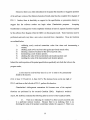
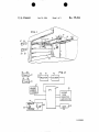
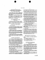
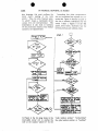
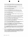
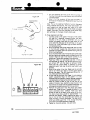
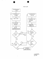
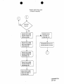
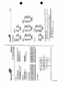
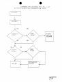
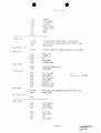
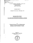
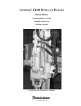
flow diagram of FIG. 3. The correct claim construction for the software Memory Selection
Switch must comport with the flow diagram of FIG.3 and, at a minimum, must include,
a software switch with dierent positions that functions to store a first
transmitter code in a first memory storage location and that functions to
store a second transmitter code in a memory storage location that is
differentfrom the first storage location.
As described more fully below, Chamberlain’s proposed claim construction is legally wrong,
primarily because it ignores the intrinsic evidence, it relies wholly on contradictory extrinsic
evidence, it improperly expands the scope defined by the patent specification by ignoring
required functions, and it specifically ignores the requirement that each newly received
4
transmitter code be stored in a memory location different fkom the location used to store the last
received code.
11.
CHAMBERLAIN’S
CLAIM
CONSTRUCTION
IS FLAWED
Chamberlain’s basis for asserting infringement is based on a legally flawed construction
of the Memory Selection Switch element. In order for Chamberlain to read its patent claims on
the accused Guardian GDOs, the claim term “code” must have a meaning that is completely
contrary to that stated in the patent specification, the file history and the meaning set forth by the
Federal Circuit in Overhead Door Corp. v. Chamberlain Group, Inc., 194 F.3d 1261 (Fed. Cir.
1999)(Exhibit E). Likewise, Chamberlain has improperly dissected the flow diagram of FIG. 3
of the patent specification to support its flawed claim construction without citing any evidentiary
authority. Finally, Chamberlain has failed to show that the accused Guardian GDOs have a code
location pointer that increments by a value of “one” until a maximum value of five is reached,
and then resets to “one.”
A.
“Code” Means Newly Received Codes - Not Previously Stored Codes
Chamberlain has improperly expanded the meaning of the term “code” to include
transmitter codes that have already been stored in memory. According to Chamberlain’s theory,
the Memory Selection Switch not only stores newly received transmitter codes, but also has the
newfound ability to move or shuffle each previously stored code to different location within the
memory. Chamberlain conveniently ignores that the patent only provides that each newly
received code is always stored in a different memory location, i.e. memory locations 1,2, 3,4, or
5. Likewise, Chamberlain fails to cite to any intrinsic evidence to support such a newfound code
shuffling h c t i o n ; instead it offers only improper extrinsic evidence of Mr. Rhyne. His recently
prepared declaration is clearly influenced by Napoleon’s non-infringement arguments, coupled
5
with the need to expand the scope of the claims in order to cover Guardian’s accused GDOs.
Moreover, Chamberlain’s unsupported claim construction is contrary to the meaning of the term
“code” found in the patent specification.
The patent specification nowhere teaches that previously stored codes are moved to
different locations during the learning operation (program mode), or for that matter, at any time
during the operation of the claimed GDO system. The word “code” is only used to refer to
newly received transmitter codes. For example, the patent specification states,
. . .wherein the receiver can be placed into a program mode wherein it will
receive and store two or more codes corresponding to two different transmitters
(Col. 1, lines 47-49).
In the program mode a code must be received four times in a row in order to
be permanently stored in the receiver (Col. 2, lines 17-19 and Col. 4, lines 3437
The switch 23 can be moved to a number of selected positions . . . to allow the
particular code of a number of transmitters to be stored in the receiver
. . .(Col. 3, lines 14-17).
Thus, the codes of the transmitters 26 and 28 are transmitted and stored in the
memory address storage 47 during the program mode . . .(Col. 4, lines 6-8).
If switch 22 is in the program mode as shown in FIG. 3 when an incoming
signal from a transmitter is received, the flow diagram is followed so as to
store the new incoming [code] in the code location pointed to by the code
location pointer 23 (Col. 4, lines 57-61).
It is seen that the present invention allows a receiving system to respond to
one of a plurality of transmitters which have different unique codes which can
be stored in the receiver during a program mode. Each time the “program
mode switch” 22 is moved to the program position, a different storage area as
determined by the switch 23 can be connected so that the new transmitter code
would be stored in that address (Col. 4-5, lines 63-67 and lines 1-3)(emphasis
added).
Each of the above excerpts from the patent specification makes it clear that the inventors used
the word “code” in the claims to mean only newly received transmitter codes and nut codes
6
already stored in memory. Indeed, the inventors distinguished newly received codes from
previously stored codes when they referred to the latter as "old codes." (Col. 5, line 4).
Significantly,the term "old codes" is not used anywhere in the any of the asserted claims.
The patent prosecution history supports this claim construction. During the prosecution
of the '703 patent, Chamberlain submitted a sworn declaration as part of its efforts to convince
the Patent Examiner that the pending claims were patentable. The declarant was none other than
Rhyne told the Examiner the following:
Mr. Thomas l3hyne. Inthat declaration, Mi-.
0
Tode'l refers to the new transmitter identity code that is to be
programmed into the GDO.
0
. . . the ''code location pointer" serves to identify the location within
the memory . . .at whch the next transmitter identity code to be
learned is to be stored.
0
. . .the microprocessor . . .uses the code location pointer . . .to
determine the location . . . at which each newly learned transmitter
identity code is to be stored.
(Exhibit I at LX 1485-86). There is no ambiguity in what Mr. Rhyne told the Patent Office and
there can be no doubt that Chamberlain used the term "code" consistently through out the
patent specification to mean newly received codes. Nowhere in the prosecution is there any
teaching that "code" or "code location pointer" refers to anything but newly received transmitter
codes. Now, to support its allegations, Chamberlain has had to resort to a complete fabrication
of the meaning of the term "code" to justify its contention that the claims read on the accused
Guardian GDOs.
The Federal Circuit opinion in Overhead Door v. Chamberlain, upon which
Chamberlain so heavily relies, supports Napoleon's, not Chamberlain's, construction of the
claim element "code." The Federal Circuit squarely addressed the meaning of the claim term
''code'' in its construction of the claim element "different codes."
7
The claim language requires association of each code with a different
transmitter. The written description notes that each code uniquely identifies a
transmitter.
The language of both claims recite "that the code of said first transmitter will
be stored in said memory means." Properly construed, this language requires
the memory to retain the code it associates with the "first transmitter."
This reading of the claim language finds support in the written description,
which explains that a code is associated with a transmitter.
(Exhbit E, 194 F.3d at 1275). Like the patent specification and file history, there is nothing in
the Federal Circuit opinion that supports Chamberlain's unsupported claim construction that the
word "code" refers to previously stored transmitter codes, when in reality it refers only to newly
received codes.
The intrinsic evidence simply does not support Chamberlain's claim
construction.
B.
Chamberlain Has Improperly Parsed FIG. 3
Central to Chamberlain's proposed construction of the software Memory Selection
Switch claim element is its wrongful attempt to convince the Court to ignore 80% of the decision
boxes of the flow diagram depicted in FIG. 3 of the patent specification. If the Court accepts
Chamberlain's construction, then four of the six stated functions of the software Memory
Selection Switch must likewise be ignored. Indeed, in its brief at page 13, Chamberlain contends
that only two of the eighteen decision boxes of FIG. 3 need be considered to construe the
Memory Selection Switch. Further, Chamberlain brazenly strikes out half the functions of the
second box, contending that the Court can ignore the requirement that the pointer value be
checked and, if over "five," reset to a value of "one." Chamberlain has offered absolutely no
support for its tortured parsing of FIG. 3. Moreover, Chamberlain's construction is completely
Rhyne told the Patent Examiner years
contrary to the intrinsic evidence, specifically what Mi-.
ago during the prosecution of the application.
8
The actions of this software memory selection switch arefully described in
Figures 3 and 4 . . . as well as at Column 4, Lines 31 through 68 . . .
(Exhibit I at LX 1485-86)(emphasis added). Nowhere in the file history or the patent is there any
mention that the Memory Selection Switch will work using the truncated FIG.3 now proposed by
Chamberlain. Chamberlain ignores all the intrinsic evidence and relies instead on the recently
prepared, litigation-induced extrinsic testimony of Mr. Rhyne. This improper extrinsic evidence
of Mr.Rhyne must be distinguished fiom Mr. Rhyne’s sworn declaration that he submitted to the
Patent Office years ago during the prosecution of the application. That earlier Rhyne declaration
is intrinsic evidence and should be considered to properly construe the claim terms.
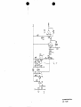
In addition to the intrinsic evidence, the Federal Circuit also indicated that FIG. 3 as a
whole describes the software Memory Selection Switch. The Federal Circuit could not have
been more clear: “Figure 3 of the ‘364 patent, shown below, illustrates how the invention
receives and validates codes. “ (Exhibit E, 194 F.3d at 1268). Moreover, the Court relied on the
language of the patent specification in construing the Memory Selection Switch:
If the switch 22 is in the ‘program’ mode as shown in FIG.3 when the incoming
signal from a transmitter is received, theflow diagram isfollowed so as to store
the new incoming [code] in the code location . . .
Id. (emphasis added). The Court further stated that “‘[s]witch means,’ when properly construed,
also covers the software-based embodiment described in Figure 3.” Id. at 1273. Accordingly,
FIG. 3 must be viewed as a whole, and not selectively dissected as Chamberlain urges in order to
read the claims on the accused Guardian devices. An examination of FIG. 3 shows that the
software routine that begins the Memory Selection Switch begins at the top right side of the flow
diagram where the label
0
A
is shown. It does not, as Chamberlain asserts, start in the lower
right hand corner.
9
Moreover, there is no other embodiment in the patent that describes or suggests operation
of the software version of the Memory Selection Switch other than the complete flow diagram of
FIG. 3. Further, there is absolutely no support in the specification or prosecution history to
suggest that the software routine can begin where Chamberlain proposes.
Accepting
Chamberlain's starting point would completely eliminate at least six separate functions required
by the software flow diagram when the GDO is in the program mode. These functions must be
performed each and every time a new code is received from a transmitter. Those six functions
are outlined below:
1)
2)
3)
4)
5)
6)
validating newly received transmitter codes four times and incrementing a
counter;
checking each newly received code against previously stored codes;
selecting a memory location for the newly received code;
incrementing a code location pointer;
checking the value of the incremented code location pointer; and
resetting the value of the incremented code location pointer.
Indeed, the written portion of the patent specification specifically sets forth that when in the
program mode,
. . . a code must be received four times in a row in order to be permanently
stored in the receiver.
(Col. 2, lines 17-19 and Col. 4, lines 34-37). The decision boxes on the top right of
FIG. 3 and those on the left side of FIG. 3, perform this function.
Chamberlain's infringement contentions fail because none of the required
functions are performed by the accused Guardian GDOs.
Napoleon's technical
expert, Mr. Gafford, concluded the following after his review of the Guardian GDOs.
2 1.
There is no indexing of a "pointer" to direct a newly received code
to a particular memory location. Because there is no indexing, there is no
checking the value of the pointer to determine whether it is equal to 5. There is no
10
resetting of a pointer if the value equals 5. And, there is no erasing of all codes in
memory when a pointer is reset.
When in program mode, none of the software on the [Guardian]
22.
product checks the newly received code to see if it already matches a code already
stored. As such, there is no repetitive checking of the stored codes. When a new
code is received and the unit is in program mode, the branch instruction at line
180 of door.asm jumps to STORI-PASS where the new code is stored in
locations 00 and 01 without regard to the other code contents of memory.
23.
Since there is no checking function to determine whether a new
code entered during program mode matches an existing stored code, the same
code can be entered 6 times. Therefore, it is possible to fill all available memory
locations with the same code.
(Exhibit G). Without those functions there is no memory Selection Switch and there can be no
finding of infringement, either literally or under the doctrine of equivalents. Pennwalt Corp. v.
Durand-FayZland, Inc., 833 F.2d 931 (Fed. Cir. 1987).
C.
Guardian’s GDOs Do Not Increment
Chamberlain’s motion for summary determination should also be denied because it fails
to establish that the Guardian GDOs perform the incrementing step required by the claimed
Memory Selection Switch. Even assuming Chamberlain’s improperly dissected flow diagram of
FIG. 3 is a correct representation of the Memory Selection Switch, there is no dispute that FIG. 3
requires that the “code location pointer” must increment after storing a first newly received
transmitter code so that it points to a different memory address to store the second or next
received code. (see Chamberlain’s brief at pages 13 -14).
“The code location pointer is
automatically incremented by the microprocessor each time the receiver learns a new transmitter
code (last action block on right).” Id. The patent specification, including FIG. 3, makes clear
that this function is a step function, where, after each newly received code is received and stored
in memory, the code location pointer is increased (incremented) by a value of “one” until each
memory location (i.e. 1, 2, 3,4, and 5) is filled. Once all memory locations are filled, the value
11
of the code location is reset to “one.”
This is confirmed by the patent file history, where
Chamberlain, through the sworn declaration of Mr. Rhyne, told the Patent Examiner,
[a]s the software loop disclosed in Figure 3 is executed by the
microprocessor unit 44, the value of the code location pointer will be
moved from one address to the next until all five addresses in memoy
that were set aside for transmitter identity codes have been used to store
learned identity codes. The specific disclosure of this loop is (a)
“Increment Code Location Pointer”, followed by (b) “If Pointer
Increments Over Five Then Load Code Location Pointer With One.” Step
(a) is the “body” of the loop; it uses the “increment” operational to
increase the value of the code location pointer by one.
(Exhibit I at LX 1573)(emphasis added). Apparently, Chamberlain and Mr. Rhyne, have
forgotten what they told the Patent Office because they now ignore the very limitation they relied
on to obtain the patent. Not surprisingly, in Mr.Rhyne’s recent declaration describing the
operation of the Guardian GDOs he is unable to identify the “increment” functionality required
by the claims. This is because there is no such function in the accused Guardian devices. The
Guardian GDOs always store each newly received transmitter code in the same memory location
(Oh). (Exhibit G). Since there is no “code location pointer” to increment by “one,” there can be
no checkmg function see if the value is “over five.” Id. And, likewise there can be no resetting
the pointer to “one.” Id.
D.
The “software controlled memory selector” Is Not A New Claim Element
Chamberlain’s argument that the “software controlled memory selector” should have a
different meaning and scope than the other claim terms used to describe the software Memory
Selection Switch is ridiculous. The term “software controlled memory selector” is not used or
mentioned anywhere in the patent specification. The only remote reference is the one instance in
the specification that refers to “the selector switch 23.” (Col. 4, linel4). Switch 23, as shown in
FIG. 2, is none other than the mechanical Memory Selection Switch. There is absolutely no
12
intrinsic evidentiary support for Chamberlain’s contention that the “software controlled memory
selector” is anythmg but the same Memory Selection Switch that is common to all the asserted
claims. Any other conclusion runs afoul of 35 U.S.C.
0
112. A phrase added to a claim by
amendment cannot enlarge the scope of the claim beyond that supported in the specification and
cannot change the disclosure in a way contrary to its substance as filed. Tandon Coi-p. v. United
States ITC, 831 F.2d 1017 (Fed. Cir. 1987).
111.
GUARDIAN’S
GDOs D o NOTHAVEMULTIPLE
TRANSMITTERS
Another reason to deny Chamberlain’s motion is that there is an issue of fact whether the
accused Guardian GDO system have multiple transmitters as required by the calims.
Chamberlain selectively relied on the equivocal deposition testimony of Napoleon’s owner, Mr.
Robert Schram, in an attempt to satisfy the claim limitation that requires the GDO system to
have a “plurality”of radio transmitters. What Chamberlain did not tell the Court was that it had
in its possession unequivocal testimony, taken before Mr. Schram’s deposition, indicating that
the accused Guardian GDOs are sold with only a single transmitter. Chamberlain learned the
true facts fiom Mr. Mark Schram who is directly responsible for purchasing of the Guardian
GDOs for Lynx,the parent company of Napoleon. (Exhibit N, pg. 13) Chamberlain ignored Mr.
Mark Schram’s deposition testimony and instead relies on the deposition of Mr.Robert Schram,
who was unclear whether or not his company sold one or more transmitters with each GDO
system. Mr. Mark Schram’s testimony, on the other hand, was unequivocal.
Q.
And Guardian Access is the supplier for the
entire garage door openers?
A.
Yes.
Q.
And they are bought from Guardian Access
directly by Lynx; is that right?
A.
Yes.
Q.
And when they are bought, are they bought as
complete garage door opener units, including the
remote control?
13
A.
Each garage door opener that we purchase
from Guardian comes with one remote control or one
transmitter.
Q.
They are sold as a package together?
A.
Yes.
Q.
Do you sell those packages together when you
sell them to your customers?
A.
Yes, one garage door opener is sold with one
transmitter. They come as a package.
(Exhibit N, pgs. 69-70)(emphasis added).
After learning of the allegations made in Chamberlain's motion, Mr. Robert Schram
personally conducted an investigation of Napoleon's corporate records and has confirmed the
testimony of Mr.Mark Schram..
I personally performed an investigation of the corporate records of Napoleon and
determined Napoleon has at all times purchased prepackaged GDO systems fiom
Guardian that include one receiver and only one transmitter in a single box. At no
time has Napoleon ever purchased a prepackaged GDO system fiom Guardian that
had more than one transmitter. Moreover, Napoleon has never altered the
prepackaged GDO system to include additional transmitters. Based on the results of
my investigation and based upon my review of my deposition testimony, it is clear
that I was mistaken when I testified that Napoleon may have tried to sell a
prepackaged GDO system with more than one transmitter. The fact is that Napoleon
has never sold a prepackaged GDO system with more than one transmitter.
(Exhibit 0,y 5).
There is no question that the claims of the patents-in-suit require more than a single
transmitter; otherwise the benefit of storing multiple transmitter codes cannot be satisfied.
Moreover, all the claims of the patents-in-suit are written as system-type claims covering a
collection of physical devices (i.e. transmitters, receiver, switches, decoder, microprocessor,
etc.), each of which performs specific functions to ensure operation of the entire system. In
order to find infingement, each of the claimed devices must be found in the accused product.
Because Napoleon has never sold a GDO system with more than one transmitter, there can be no
14
direct infringement of the claims. At a minimum there is a genuine issue of fact as to whether
the accused devices have the required "multiple" transmitters.
IV.
GUARDIAN'S
GDOs D o NOTHAVEA DECODER
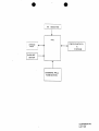
Another structural element required by each of the asserted system claims is a "decoder."
The patent specification describes only one embodiment of the "decoderf'and does not disclose
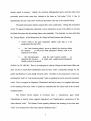
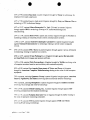
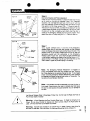
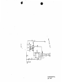
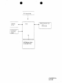
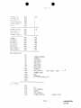
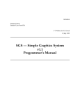
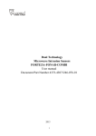
or suggest any other acceptable alternatives. In fact, the patent specification refers to FIG.2
when it describes the operation of the decoder.
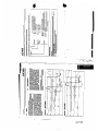
As illustrated in FIG. 2 the garage door operator includes a receiver 41 which has
a suitable antenna 42 for receiving radio frequency transmissions from the
transmitters 26 and 28 and supplies an input to a decoder 43 which provides an
output to a microprocessor unit 44.
(Exhibit Cycol. 3, lines 1-5) As shown below, FIG. 2 of the patent specification supports the
above-stated written description because it clearly shows that "decoder" 43 is a stand-alone
device that is directly connected to "receiver" 42 and "MPU"44.
2
15
No other description of the "decoder" is found in the patent specification. Using FIG. 2 for claim
interpretation is proper because the Federal Circuit in Overhead Door v. Chamberlain likewise
used FIG. 2 to interpret the meaning of the claim term "switch." The Court stated that,
[T]o interpret the term ''switch'' consistently in the claim and to harmonize the
drawing depiction [FIG. 2) with the claim langaage, this Court confirms the
district Court's reading of the term "switch."
(Exhibit E, 194 F.3d at 1267). This same "harmonization" requirement equally applies to the
term "decoder," and requires that it be construed as a separate device that receives input from the
"receiver," performs a decoding function and sends its output to a microprocessor (i.e. the
Napoleon's technical expert, Mi,Gafford, has reviewed the the intrinsic evidence and
concluded that one skilled in the art would construe the claim term "decoder" to mean the
following:
The "decoder" is a separate electrical device that is electrically connected to a
receiver and a microprocessor. The function of the "decoder" is to receive coded
transmitter signals from the receiver. The "decoder" then decodes the transmitter
signals and sends the decoded signals to a microprocessor for further processing.
(Exhbit P
-
Para. 7 Gafford's Second Supplemental Decl.). Following the reasoning in Bell
Atlantic, Chamberlain has consistently used the term "decoder" throughout the patent
specification and has provided no alternatives, thus no greater breath than what was originally
disclosed by Chamberlain can be accorded.
Bell Atlantic Network Sew. v. Covad
Communications Group, 262 F.3d 1258,1271 (Fed. Cir. 2001).
Mr. Gafford's study of the accused Guardian GDO reveals that it does not have a
"decoder" as that term is used in the asserted claims.
16
8.
The Guardian GDO, specifically the controller does not include a separate
and independent decoder device such as the decoder illustrated in Figure 2 of the
'364 and the '703 patents. Rather, when the Guardian GDO receives a transmitted
code, the transmitted code is received by a radio frequency demodulator. The
output of this demodulator is directly connected to a CPU, not a separate and
independent decoder device. There is, therefore, no separate and independent
decoder unit connected between a receiver and a microprocessor as those terms
were used by the inventors of the '364 and the '703 patent.
(Exhibit P - Gafford's second supplemental declaration). Because the Guardian GDOs do not
have a "decoder" there can be no literal i d g e m e n t . Although Chamberlain did not assert
infringement under the doctrine of equivalents, there could be no such finding because there is a
substantial difference between the claimed "decoder" as a separate device connected to a
receiver and MPU, and Guardian's software subroutine program that is integral to its
microcontroller.
V.
CONCLUSION
Chamberlain's allegation of infringement fails because its proposed claim construction is
flawed. The intrinsic evidence does not support Chamberlain's attempt to expand the scope of
the claims with respect to the software Memory Selection Switch, decoder, and multiple
transmitter elements. The Chamberlain patent specification discloses a single embodiment of the
software memory Selection Switch and makes absolutely no mention that alternative functions
are possible. Therefore it is improper to construe the disputed claim terms to have a meaning
any broader than that supported by the intrinsic evidence.
Chamberlain's patents require a software Memory Selection Switch that performs a
number of functions, including directing newly received transmitter codes into a memory
location that is different from the location where the last received code was stored. The
Guardian GDO does not have the claimed software Memory Selection Switch because the
Guarhan GDO always stores each new transmitter code in the same memory location. Further,
17
the Guardian GDO does not perform any of the many functions required by the software
Memory Selection Switch. Additionally, the Guardian GDOs are sold with a single transmitter
and do not contain a “decoder.” For these reasons, there can be no finding of literal infhngement
or infi-ingement under the doctrine of equivalents.
Therefore, Chamberlain’s motion for
summary determination should be denied.
Respectfully submitted,
Date: November
V
I
-
r
2001
David M. Frischkom
A. Blair Hughes
Thomas E. Wettermann
Jeremy E. Noe
McDonnell Boehnen Hulbert & Berghoff
300 South Wacker Drive
Chicago, Illinois 60606
Telephone: 3 12/913-0001
Facsimile: 3 12/913-0002
George M. Sirilla
Arthur Wineburg
D. JamesPak
Pillsbury Winthrop LLP
1600 Tyson Boulevard
McLean, VA 22 102
Telephone: 703/905-2000
Facsimile: 703/905-2500
Attorneys for Respondents
LYNX INDUSTRIES, INC.,
NAPOLEON SPRING WORKS, INC.
GUARDIAN ACCESS COW.
18
CERTIFICATE OF SERVICE
I hereby certify that a copy of the Foregoing Respondents Lynx Industries, Inc., Napoleon
Spring Works, Inc., & Guardian Access Corporation’s Memorandum Opposing
Chamberlain’s Cross-Motion for Summary Determination has been served on this 13thday
of November 2001,as indicated, on the following:
VIA COURIER
Hon. Sidney Harris
Administrative Law Judge
U.S. International Trade Commission
500 E Street, S.W. - Room 317-G
Washington, DC 20436
(2 copies)
Ms. Donna R. Koehnke
Secretary
US.International Trade Commission
500 E Street, S.W. - Room 112
Washington, DC 20436
(original & 6 copies)
David 0. Lloyd, Esq.
Office of Unfair Import Investigations
500 E Street, S.W. - Room 401-M
Washington, DC 20436
(1 COPY)
Thomas M. Schaumberg, Esq.
Michael L. Doane, Esq.
ADDUCI, MASTRIANI & SCHAUMBERG, LLP
1200 17thStreet, N.W. - 5thFloor
Washington, DC 20036-3006
Counselfor Complainant
(1 COPY)
VIA FIRST CLASS US.M I L
John F. Flannery, Esq.
Karl R. Fink, Esq.
FITCH, EVEN, TABIN & FLANNERY
120 South LaSalle Street - Suite 1600
Chicago, IL 60603
Counselfor Complainant
(1COPY)
Ramon R. Hoch, Esq.
FITCH,EVEN, TABIN & FLANNERY
1801 K Street, N.W. - Ste. 401L
Washington, DC 20006- 1201
Counsel for Complainant
Philippe M. Bruno, Esq.
DORSEY & WHITNEY LLP
1001 Pennsylvania Avenue, N.W.
Suite 300 South
Washington, DC 20004
Counselfor Respondent Wayne-Dalton Corporation
Ray L. Weber, Esq.
Phillip L. Kenner, Esq.
RENNER, KENNER, GRIEVE, BOBAK, TAYLOR & WEBER
First National Tower, Fourth Floor
Akron, OH 44308-1456
Counselfor Respondent Wayne-Dalton Corporation
(1 COPY)
W. Joseph Melnik, Esq.
Raymond A. Miller, Esq.
BENESCH, FRIEDLANDER, COPLAN & ARONOFF, LLP
2300 BP Tower
200 Public Square
Cleveland, OH 441 14-2378
Counselfor Respondent Innovative Home Products, Inc.
(1 COPY)
'
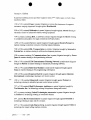
United States Patent
~191
Heitschel et al.
11111llIllU1tllll lllrnCSOORE35364E
1111I111 lllll111011111~1111111H
1lil 1111
!451
SYSTEM FOR MVJTIPLE
TRI.USMKTERS k*iDA SINGLE RECEIVER
FOR A G A U G E DOOR OPEXEX
[S4] CODBG
[75] inventors: Cui Bcirschcl. Downen Grove; Colin
W b o t f Buffalo Grove. Wayne
%hinder, Lisle. all of Ill.
(731 Assipce: The Chvnbertnin Group, Iac,
Elmhurst, Ill.
(211 Appl. No 425,724
Apr. 20, 1995
[22] Ned.
Related O.S. Patent Documen&
Reissue of
4,730,118
Jun.7, u88
792,661
Oct 29, 1985
[ 641 Patent No.:
Issued
4ppl So:
Fllcd:
U S. Applicauons:
[63] Coounuauon of Ser. No 87.142, Jul. t. 1993. abrndund
which u a c~nunuanooof Sa. No 715.006, Jun. 13. 1991,
abandoned, whrch s a conunuazoo of Set. No 398379,
Aug. 24. 1989. abaudaaed.
[51] I ~ C1.b
L
......_............ Go6p 19/00: G08C 19/00,
E05F 151'20
(521 US. CL .....-................ 364/400, 49125; 34W825.69;
3aa25.73
[58] Field of Search ....................
........_..364f130. 400,
364167 01.825.04,a;?5.3.825.31. 825 44.
525 56, 825 69, 825.71, 825.72 825.73.
825.74. 8x.is,82s 76.539, 542,543;
49R5, 28. 31, 70. 324; 318/16. 262-266,
282.4-68;
3611171, 172; 4 ~ 5 / 1 8 6 . 1 ,
186.2
(561
References Cited
US. PATENT DOcu%4Ems
Re 29525
3.911.397
4.037201
4.081.747
4,li9,896
VI978
1U1975
311977
31978
1Ul978
................................ 31-51'37
.................._340/147 MD
..............
340t167 R
Mcycrle ................................
315137
Estea. IIIetaL .....-....._.......318/266
Wdlmou
Fmny. Ir.
Whon
Re. 35,363
Patent Sumber:
(111 E
Reissued Date of Patent:
Oct. 29, 1996
1: .978 Smdriedr . . . . .
17990 B
549 I: .Sr9 U e n b a c h et al ............. 32538 R
4262.536 I
.381 Le Q al. ................. ......... 31U266
4,130,738
4.1'8
(Ls!continued on next page.)
F O W G S PATEST W C L 3 l E . S
0099762AI
OI433WJ
02120jOA2
0319781192
04016i3Al
0561361141
OS63517Al
2746332Al
2856337
2939S89AI
2941394Al
55-114771
59-80872
lJ3126
X984
Empan P~I.Off.
61983 Empan Pa Off..
5 1987 E~vopernPu. Off..
6 !989 Eumpau Pet Off..
:11990 Empn Pat. Off.
f:993 E w p u P
~a OtT
!C!.993 Europu~Pat OI
11979 Ccrmany .
1980 G e r m ~ y
41981 Gcrmrny
&I981 Germany
&!980 l a p a
5.1984 Jtpap
S 1974 Cmed Kingdom
-
OTHER PL!LICAIIONS
"Garagenroranu.::, mi Funldernsteuemng." by Tocsf.cn
Mcyer-Sraofem:e!, pp 115-117. dared 1975.
Alluonrk 0ppos:zon Bnti of Jul 8,1990, correspoodmg 10
German Paunr So 36 75 555
Donna Opposiran Bncf of Aug. 8. 1990 of comspoadmg
German Parent So. 36 25 555.
P n m a ~€xmuir-Jowph Ruggrcro
Anornq Agcnr. or Firm-Filch, Even. Tabtn & Ranaery
(57
ABSTRACT
The present invenon compnses a system for remote coauol
of garqe doon md other devices whernn an exmmely
laqe number of d e s are avdable for remote *ransrmnm
for opeating rh p a g e operator and wherein each mansmncr has 11s o m umquc and permanent nonuser changeable code. The receiver ai rbc garage door operalor IS
capaolc of s t d z g and r c m c m W g a n u m k r of Merent
d e r ccrrcspodng IO &ffcnnt ui~11sm1rers
such that 'he
receiver can be ?panned so as to acwcd by more rhan
one rraa~rmncrcode hus a l l o m g two or more rransmnert
to a c w the s a c garage door operator and wherein rhc
receive: siom LZ'vahd codes for the different uansmnen
'
8 Claims. 3 Drawing Sheets
LX 0001
Re. 35,364
Page 2
....
L S P A E W DOCLXE?-TS
4.29l.4[1
4.305.060
4.3228S5
4.328360
4,385296
9/1981 MUa e: ai
lU!981
3/1932
.................... OS5 3S
.... I'O/agt,.-J
.......... :s5/:;:
511992
5/!983
4.418333 1111983
340aE Ai
4.42L071 1211983 D c G d ...................._.
63
4.454309
6l1984 Bueaugel et a l ..............
e ..............."....._._..
3@f0/521
U19& D
318132
4,491,714 !I1985 .S&I@JK. ........... ......_...._...._
36K'?.
4.509.093 411985 Srellkrger ............_._...._...
Lionne
et
al
.........
w
8zJ1
4529.980 711985
4.464.651
4.535.333
Ui985 T w d o w r h
...........
34W8Z 59
4550.311 la1985 Galloway et ai
4.J81.606 441986 M a l l O q ..........
4596.985 6'1986 BOngYd et al . . . . . . . 3401325 69
4.602.357 711986 Ymg et al .........
367f33
4.633.247 I31986 Hegelv ........................
340183 69
4.638.433 1/1987 ScSmdln ......................
3Wal
465LS60 31987 Weohaupi e: al. ...........34(u539
4.66f.3~ 5119~7P ~ O W....... ......_..........
~wazs6
4153.792 '111988 Psuolo ei al ................... 34111538
4758.835 7/1986 Ratimam et ai ...............MU825 31
4.866.434 911989 Keellan ................
.- 30182572
4.878.052 !W!989 SchuLze ....~
_..._......
..... 360/825 69
4.912.063 311990 LI .............-..........
...... 3W82.569
4,988,992
If1991 Heiuchcl et J. . ........_....34W825 69
LX 0002
US. Patent
27
p
Oct. 29, 1996
Re. 35,364
Sheet 1 of 3
FIG 2
26
28
[ i - c
47
I
MEMORY
ADORE SS
STORAGE
GARAGE
0 PERAT I 0 N
M K H A N ISM
19
OPERATE'
z.l,
d23
38
PROGRAM
LX 0003
U.S. Patent
Oct. 29, 1996
GI---
DETECT A BLANK
Sheet 2 of 3
FIG. 3
Re. 35,364
Q
START
81T C O M E
&7
START
TIMER
(>
YES
MULTIPLE WlTH RESPECT
STORE CODE AT LOCATION
POINTED TO BY T H E C O D E
LOCATlON POINTER
I
POINTER. IF POINTER
INCREMENTS OVER fIVE
THEN LOAD COOE LOCATiON
LX 0004
U.S. Patent
Oct. 29, 1996
Re. 35,364
Sheet 3 of 3
FIG. 4
CLEAR ERROR COUNTER
AND ALL OTHER VALID
(COUNTERS
INCREMENT THE
ERROR COUNTER
.
\CLEAR ERROR
COUNTER AND
ALL VALID
COUNTERS
II
1
I
INCREMENT T H I S
VALID CODE
I
A
r e
I
1LJ
1
ACTIVATE PROPER
OUTPUT
START
I
,
FIG. 5
PI I
I
svkc.
LX 0005
Re. 35,364
1
CODCiG SYSTEM FOR .MLZTIPLE
TRCYSSIITTERS AYD A SISGLE RECEIVER
FOR A GAK4CE DOOR OPESER
Matter enclmd in heavy bradretr [ ] appean in the
on@
patent but forms no part of this rrissue rpccificaaon; matter printed in i t a i i a indicates the additions
made by rcizsue
This applicanon is a contmwtwn of application Srr.No.
087,142 filed Jui 2, 1993. abandoned which u a coniinuanon of appkanon Ser: No 715.006, filed Jun. 13. 1991,
&andom4 which u a conmuation. of application Ser No
398.379filed Aug. 24, 1989 abandoned
CROSS-REFERENCES TO RELATED
M P U CATIONS
Ths application compnsu; an tmgovcment on applicanon Ser No. 615.339, filed May 30, 1984, U.S. Pat. No.
4,638,433. LCI whch the tnvcntor is Wayne R. Schmdier
assigned 10 the assignec of the present application.
BACKGROUND OF THE INvprTION
I. Field of the bvecnon
This invcnuou rdarrs m gcnnal16 garage door operaton
and m particular to a novel g q e door o m o r whcrcln the
receiver can be e n e r g i d by two or more uansmtrud c o d a
whrch are stored m the receiver.
2. Dexnpuon of the mor AXI
Garage door operators o f the prior an used uansrmners m
which the code can be changcd by vanous methods as. for
example, by movlng two posinon switches to change the
code. Such systems have Jso used code changing swtches
UI the receiver so that the receiven can be set to correspond
to the sclccred villlSmncr code.
It has also been knowo to use b x d frequency uansminers
and fixed frequency :ecavcrs such that if the uammiucd
fhquency marches the Tc(nyer frequency the m v c r will
rcspoud.
S L W Y OF THE LNVEhTON
2
to provide drfferent c h g s . Each datum can k I 2. 3 or 4
umcs the length of the sync puise. The tirmng is from the
nsing edge to nsing edges of the pulse and wxh un dam bits
the number of c o d a can tc UI excess o f one mllion codes
In the mvention, each V;LOSnUtItf encoder will conran a
chtp which conmns a umqce code and the receiver wrll be
able to memonze two or more as. for example, five dxffercnt
uansminer codes. This ehrmnates the need to have codmg
swtches in e i t h the
~ uansmtca or rCfCivcr. T h ~ehrmnater
i
the rcqmmcnt that the user set the code swtches so bey
match since rhc code switches are elirmnated.
In the mvention, d u n g an opcrafc mode, a receiver code
must march an already proprammed code fora tlmez in order
IO o p e m the garage door. Ths m c h IS referred to as a
valid code. Each vahd code can be r p a m e d by up to iwo
ermr codes and sriU have rhe outpur lndrcattd as accurate
In the program mode a code must be received four umcs
in a row in order to bc pemanenlly stored LU the receiver.
Any e m r code wlll r e ~ e tthe vahd code counur.
The advantage of the coding scheme arc:
1. Higher peak power Mthout exceeding the FCC rules
which gvu longer tranirmm range.
2. Elirmnate w d c switc!xs m the tnnsmner and rece:va
making 11 easier for a cutomer to install and opeme hrs
garage door operaror.
3. Customrs having mre &an one UMSUU~K wll not
have [o match codes.
4 More secure codes due to the higher number of
combmmom whtch are avadable. Other ObjeaS, f e w
I
and advantages of the invenuon prill k lradily apparent
from h e following dexnpuon of c:wn prsfemd embodiments thereof. ukcn in mnjuncuon wrh the accompanymg
drawrngs although vanacons and rnodificauons may be
effected wrhout depamng from the iprnt and scope of h e
novel concepu of the divlosm and m w h x h
BRIEF DESCRIPIlON OF THE DRAWINGS
FIG. 1 is a p e a ~ d v eview illusuaaag a garage d m
operator;
FIG. 2 iilusuaru in block fonn the hvenuon,
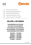
FIG. 3 compnscs a Row diagram
FIG. 4 is a conmuanon of the flow diagram; and
FIG. 5 lllusuaru the coding scheme.
It IS an object of rhc present mvenuon to provide a
plurabty of msmmrs w h m m cach transminer has its own
usque and permanent UOU-USU changcablt C D ~ Cand
whereln the receiver can be placed into a progmn mode
wherein it wdJ receive and swre two or more codes cornsponding to two d.iffercnt msmnen. The number of codes
DESCRIPTION OF THE PREFERRED
s be extremely hgh as. 50
wruch can be srorcd rn ~ m t u r can
EMBODIMENTS
for example, grzur rhan one nullion coda. Thus, the
invenuon makes it pcssible LOelirmnate rhe rcqturcments for
FIG 1 lllusvara a garage door operaror 1 0 mounted to
code sciccuon switches m the uansmmn.
the ceding of a garage and conocctcd ro o p r r a door 17
In h e present invenuon the decoder module in the 25 Garage door operator 10 has a head u t 11 whch is
receive? unll be capable of learmng several hfferent uanssupponed from the c e b g whtch ~ ~ c l u d eas motor whch
mined codes wtuch pnll ekrmnatc code swttches VI the
dnves a suirable cham to whch a volley 13 is attached so
fcccivcr and also prnvidcs for muinpie UansmKCrS for
[hait moves along a d U.The volley 13 has a release cord
acruaung the 3arage opener.
20 and pivotally camcs a lever arm 14 whch IS anached to
a bracket 16 mounted to rhe door so ar to mse and open it
The wrnmuzucarion link can be various system such a
by pulling it dong conmmonal ds.
radio frequency, light. wues, ctc.
The header WL 11 tncludcs a receiver and operaung
Tbe tnvenuon makes it v m easy for rhe user to operate
mechanism and can k actuated from a conuol mt 38 whrch
the system and more scared code iysrcms are avulablc due
has a o w switch 39.
to the bghcr number of available codcs.
An encoded signal wrll k utilized wherein a pulse and 65 The gangc d m operator cau ais0 be o p m e d by the
nansm~m26 and 28 wtuch have opcntc uansmit bunons
blank nmc compnscs a sync m e base and different lmk
27 and 29, respccuvcly.
pulses such as 1,2. 3 or 4 rmllixconds can be selected SO aS
LX 0006
Re. 35.364
3
4
As .llusnated in FIG. 2 the garage door operator includes
a receiver 41 which has a suitable antenna 42 for receiving
radio frequency transmissions £1-om the uanstnitters 26 and
28 and supplies an input to a decoder O which provides an
output to a microprocessor unit 44 fie microprocessor unit
44 is connected to a garage door operator mechanism 46
which includes the motor which d.t‘l‘v¢S the chain 15 to move
the door 17 in a conventional manner. The control 38 is
connected to the microprocessor 44. A pair of switches 22
and 23 are mounted on a switch unit 19 connected to the unit
11 and also to the microprocessor 4-4. The switch 22 is a two
posiuon switch that can be moved between the operate and
program posiuons to establish the ‘‘operate'‘ and “program"
modes. The switch L3 can be moved to a number ofselected
positions indicated by the 1 through 5 so as to allow the
particular code of a number of diflerent transmitters to be
stored in the receiver so that the receiver will respond to
such codes.
storage location. ‘Rico the switch 22 is moved to the operate
posiuon and when either of the transmitters 26 and 28 are
energized. the receiver 41 decoder 43 and microprocessor 44
will energize the garage door operation mechanism 46 to
cause the door to either move up or down depending upon
its tniual position. Thus. the codes of the transmitters 26 and
28 are transmitted and stored in the memory address storage
47 during the program mode after which the garage door
operation mechanism will respond to either of the :anstrutters 25 and 28. Any desired number of transmitters can be
programmed to operate the garage door mechanism its. for
example. up to five transmitters can be programmed into the
memory address storage 47 by using the program switch 22
and the selector switch 23.
In the illustrated embodiment. the receiving urut can
respond to up to five difierent transmitters which have Five
difierent ttansmimng codes. FIG. 5 illustrates the code
utilized in which the bit times are nominally 0.5 milliseconds for example. The data umes are nominally l, 2. 3 or 4
milliseconds.
The sync pulse is a unit measure of time. Each datum is
measured with respect to the sync pulse and each danini can
be 1. 2. 3 or 4 times the length of the' sync pulse The t.i.tri.in3
is from the rising edge to rising edge of adjacent pulses.
Using 10 data hits the number of codes which is available is
in excess of one million codes.
in the invention, each transmitter such as nansrniners 16
and 28 will have a unique code which is determined by the
encoder chip contained in the transminer. The receiver unit
will be able to memorize and store a number of diflerent
codes as. for example. five difierent transminer codes which
eliminates the need of coding switches in either the transmitter or receiver which are used in the prior art. This also
eliminates the requirement that the us: match the transmitter and receiver code switches.
When the garage door operator is initially installed. the
switch 22 is moved to the program mode and the energize
button 27 of the first uansniitter 26 is depressed so that the
uruque code of the transmitter 26 is oanstnitzed. ‘Bus is
received by the receiver 41 and decoded by the decoder 43
and supplied to the microprocessor unit 44. The switch 13 is
placed in the first position. and with the switch 22 in the
program mode the code of the tiransrnitter 26 will be supplied
to the memory address storage 47 and stored therein. Then
if the switch 22 is moved to the operate mode and the
transmitter 26 energized by depressing the transmit switch
27. the receiver 41. decoder and the microprocessor 44 will
compare the received code with the code of the trarisrnittcr
26 stored in the first memory location in the memory address
storage 47 and since the stored memory address for the
transrniner 26 coincides with the trartsmitted code of die
tiansmiucr 26 the microprocessor 4-4 will energize die
garage door operation mechanism 46 to open or close the
door.
Ln order to store the code of the second uansniitter 28 the
switch 22 is moved again to the program mode and the
switch 23 to the second position and the transminer 28 is
energized by depressing its transmit switch 29. This causes
the receiver 41 and decoder 43 to decode the transmitted
signal and supply it to the microprocessor 44 which then
supplies the coded signal of the ttansrrntter 28 to the memory
address storage 47 where it is stored in a second address
This invention eliminates the requirement that binary
switches be set in the transiruner or receiver as is done in
systems of the prior art to establish a code to which the
receiver will respond and the invennon also allows a garage
door operator to respond to a nutnber of difierent uansnutters because the specific codes of a number of the transmitters is stored and retained in the memory address storage 47
of this unit.
FIGS. 3 and 4 comprise the flow chart which describe
both the operate and program modes of the invention.
Basically. in the operate mode, a received code must match
a program which has already been programmed and for four
times so as to operate the garage door. This match is referred
to as a valid code in the flow chart. Each valid code can be
separated by up to two error codes and still have the output
actuate. For example. a code of valid-error-error-va.'tid-validvalid would actuate the door. On the other hand. a code of
valid-valid-valid-error-error-error-valid would not actuate
the door.
in the program mode a code must be received four times
in a row in order to be permanently stored. Any error code
will reset the valid code counter.
with reference to the flow diagrams of FIGS 3 and 4 if it
be assumed ininally that the switch 22 is in the operate
position an incoming signal will be supplied to terminal Ain
FIG. 3 and an output will be supplied to terminal B which
indicates that the switch 22 is not in the program mode but
in the operate mode. Terminal B is illustrated in FIG. 4 and
the microprocessor compares the incoming code with any
codes in the Eve code locahoos stored in the memory
address storage 47. If these codes match then the error
counter is cleared and all other valid counters. if the valid
counter receives the code four times than output is supplied
to the terminal C which operates the garage door operator:
if the valid counter for the code equals less than 4. then the
valid code counter is incremented until the valid code
counter does not equal 4 which actuates the proper output
Relative to FIG. 4 if the input code does not match any of
the five stored codes. then the error counter is incremented
and when the error counter equal 3 the error counter is
cleared and all valid counters are cleared.
If the switch 22 is in the program mode as shown in FIG.
3 when the incoming signal from a transminer is received,
the how diagram is followed so as to store the new incoming
program in the code location pointed to by the code location
pointer 2:. It is to be noted that up to five addresses can be
stored in the system of the invention.
it is seen that the present invention allows a receiving
system to respond to one of a plurality of transmitters which
have difierent unique codes which can be stored in the
receiver during a program mode. Each time the "program
mode switch" 22 is moved to the progiam position. a
LX
LX 0007
0007
Re. 35,364
5
ddferent storage a n a as dete.mned by the switch 23 can be
corsected SO that rhe new Ifail5IIllKtf code would be S I O d
in thai address Afer all of the address storage capanty have
been used a d & u o d cock would ease all old codes in the
memory address storage before rronng a ncw onc.
Alrhough the invenuon has been descnbed with respect Lo
p r e f e n d embo&menu, 11 1s 001 10
Iimled changes
6
4 A w a g e door operator accordag (0 clam 3 wherem
L!e Code stored in sad memory means can be c b . g e d by
P h n g s a d switch in rhc program mode and one of s a d
P l d t ) . Of VanSnuKeS IS eCe:gized whch has a code whch
5 hfferr h
rn the code p:cnously stored a sad memory
llleans
'e. 'pernror for cOnrrO"ing opranon of eqwpmnr
Compnsug a radio receir er a decoder connecred ro m e i b e
rhr o q w of said radu receiver: a microprocessor connecred ro receive ihe owpu of sad decoder and io sad
eqvipmrnr Io energi:e if. jrsr nvirch means jor seiecrion
beween program and operate posifionr connected ro satd
microprocessor ro place s ~ r dmicropmessor m
operare
or the pmgram mode, u mcmory mcm for rromg a
plvruhq of uddrcsses connecid ro s a d mlcmpmessor
when snldjrsi nvirch m k ? ~
IS rn rhc p m g r m posirun, a
mmn selecnon second nvrrch meum connecred io said
micmpmcessor a p l u r a l r ~of radro Transmiirers xuh dif
f e r e a codes. surd memory selecrzon second wirch mems
beurq adapted IO selecr ufisr position 01 u lune %henP first
20 one oj sad rudio rrmmzters u eneqized so rhar rhe code
of saiafirsr r r m i n e r wll be srond in said memory m e a m
and sold mcmory selecrion second m r c h means bemg
a d u p i d lo s e l m a second psirion or a hme when a second
one of sard rdio rranrmurers u energized so rhar r
k code
2s of said second r r m m m r wll be swred in r a d memory
mans, and sold nucmpmcessorphced IJI rk operate mode
w k n rordfinr swirch maw ts in rk operare posiron 50
rhot cnhcr or borh of s a d first and second radio rroNmiirers, u k n energized c-e
sad mcmprocessor ro encrgue
30 s a d equlpmnr.
6. At operaor accordug o clam 5 wkrevl saidJirn a d
second r&
rrONmtnerJ when energued rudure codd
signak and sad mrcmpmcesJor recenw Md compares
coded signals from saidfirst and recond rransmirters wirh
35 codtd ngnak srond rn scud memory means and sad micmpmceuor pmduces an operate signal fl fhe received Irammiired signal and any one of sad coded signals siored in
sad memory muvu match
7 An opcraror uccordmg fo clam 6 wherein surd second
switch mans. has "n"ponfionrwhere '"n" is an rnregerand
rk c&s of "n" rranmuners c m be stored m s a d memory
meam k k n surdfirst w t c h means u m rh: program mode.
8. An operaror accordur8 ro clam 7 wherern rk code
srond YI sad mmo~mans can be changed by placvlg
)5 sardftrsr switch m e w rn rhe p m g r m mod: and one of sad
zutch.
3 A garage d m operator according 10 clam 2 wherein
pluralq of iransmirrersLS energized whrch IIPF a code which
sard memory selecuon swrsh has "a'* posi~onswhen "u" IS
differs fmm [he code previouly srored rn sard memory
an mtcger and *e codes of "n" vansrmnen can k stored in
meum.
s a d memory means when sad switch is m rhc program
and m ~ f i c a a o m may
de
wtuch are w,lhrn
intended scow BI defined by ihc appended clams.
We c l a m a ow mvenrion.
1. A garage door 'JPemor faa garage door CoVnSW.
a garage door O P ~ Q O O m ~ ~ h a swith
m M OUPU~ shaft
connected a said garage door 'D O
w and ClOsc 11. a rad10
f ~ c c i v u a. decoder coM-%ted IO ITCelve rhC Ourput Of said
d o receiver, a rmcroptDctslor connecled u) receive the
output o f s a d decoder and IO s a d garage door operation
rnechanrsrn to eneqte if a switch moveable helweeo program and operate p u o n t cqnnatcd to s a d rmcmproceSjot to place s a d mcroprocetsor UI h e operate or p:ogram
mode, a memory mcam for stonng a plu~al~tyof addresses
connecred to said uucroprccesror when s a d switch is io the
program position. a memory sclccuon switch connected to
s a d m c r o p c s s o r . a pluality of radio transmners wlh
-different
codes, sad memory selection switch setable in a
6
n
s
t posiuon at a umc when a , h t one of sad radio
V a ~ r m e t e n IS mcrgued so that the code of w d 6nnt
' ~ ~ ~ ~ I N
wilI
L Ibe
U stored in u d memory mearu and s a d
memory seleeuoa swtch xt UI a second poriuon at a umc
when a second one of a d radio uansmimn h energized so
that the code of m d wcond uansrmpu mll k stored in sad
nemory means. and said mcroprwssor placed m the
opzrate mode when said swtch is in the opcrau p i n o n so
that eirhu or both of said 6 n r a d second radio m m w
when encrgucd c a w s a d rmcroprocessor to encrpzc sad
g a a g e door opntor mechaasm
2. A garage door operator for a garage door according to
c l a m 1 wherem s a d b t and second d o uansmacn
when energmd radiate coded signals and s a d mcroprow1or receives and compares c&
signals fmm m d h t and
second nansmm with coded signals b
o
r
n sad fint and
second vansm~cn wth coded signals stored in m d
memory means and said mcroprocusor produces a garage
door operate signal dibc received uansrmtud signal and any
one of s a d coded signals stored in said memory means
mode.
*
.
.
.
.
a
LX 0008
OVERHEAD DOOR CORP.
v.
CHAMBERLAIN GROUP,
ISC.
Citeas 194 F 3 d 1261 (Fed.CIr. 1999)
1261
of the Brewster machine pointed out numerous features which were distinguishable from the preferred embodiment of
the invention. However, only one of these
features appears as an express limitation
of each of the disputed claims, namely, intermixing the microingredients in the liquid before discharging them into the feed
ration. The Brewster system did not intermix the microingredients in the liquid
canier-presumably
because such intermixing would interfere with the weighing
operation.
This court notes that the prior art did
not “perform[ ] the claimed method” as the
district court suggests.
Rather the
“claimed method” is the unique combination of steps found in method claims 63,93,
and 94-not any single step in isolation.
The prosecution history suggests that the
applicant avoided the prior art by including an intermixing limitation in the claims.
The prosecution history does not suggest
that the applicant disavowed the weigh
dump method. The district court erred by
interpreting these statements in the background section of the patent and the prosecution history as a disavowal of the weigh
dump method.
chines. The undisputed facts do not establish the knowledge necessary to find inducement to infringe. The district court
appropriately granted summary judgment
finding Mr. Hummei not personally liable
for inducing Lextron’s infringement.
Mr. Hummel’s Personal Liability
OVERHEAD DOOR CORPORATION
E15-171 Officers of an allegedly infringing corporation can be held personally liable for actively inducing infringement under 35 U.S.C. 3 271(b) only if they “knew
or should have known [their] actions would
V.
111.
In conclusion, this court reverses the
district court’s entry of judgment of noninfringement with respect t o claims 63, 71,
93, and 94, but a f k s with respect to
claim 91. This court affirms the district
court’s grant of summary judgment finding
Mr. Hummel not personally liable for inducement to infringe. The case is remanded to the district court for an assessment of damages,
COSTS
Each party shall bear its own costs.
AFFIRMED- IN-PAR T, REVERSEDIN-PART, and REMANDED.
w
0
KEY NUMBER SYSTEM
and GMI Holdings, Inc.,
Plaintiffs-Appellees,
The CHAMBERLAIN GROUP,INC.,
Defendant-Appellant.
induce actual infringements.” ManviZZe
No. 98-1428.
Sales COT. v. Paramount Sys., Inc., 917
F.2d 544, 553, 16 U.S.P.Q.Zd 1587, 1593
United States Court of Appeals,
(Fed.Cir.1990).
Pre-issuance activities
Federal Circuit.
alone cannot establish inducement to inOct. 13, 1999.
fringe. See National Presto Indm., Inc.
West Bend C0.v 76 F-3d 11% 11% 37 Rehearing and Suggestion for Rehearing
U.S.P.Q.2d 1685, 1693 (Fed.Cir.1996). MiEn Banc Denied Dee. 16, 1999.
cro Chemical brought this suit two days
after the patent issued, at which time Mr.
Manufacturer of remote control gaHummel took reasonable steps to avoid
infringement. Among other things, Mr. rage door opener systems brought declarHummel sought and relied on the advice of atory judgment action asserting that mancounsel in redesigning the accused ma- ufacturer’s “Intellicode” system did not
-,
I
1262
m E D E R A L REPORTER, 3d SERIES
infringe patents. Patentee counterclaimed,
alleging willful infringement. The United
States District Court for the Northern
District of Texas, Sidney A. Fitmater, J.,
granted summary judgment of noninfringement, and patentee appealed. The
Court of Appeals, Rader, Circuit Judge,
held that: (1) term “memory selection
switch” meant a mechanical device, separate from the microprocessor, with different positions; (2) first claim at issue was
not literally infringed, but fact issues existed as to whether it was infringed under
doctrine of equivalents; (3) term “memory
selection switch means” encompassed both
a mechanical switch and a software-based
embodiment; (4) fact issues existed as to
whether second disputed claim was literally infringed; and (5) “switch moveable”
element, “first switch means’’ element,
and “different codes” element were present in accused system.
Affirmed in part, vacated in part, and
remanded.
1. Federal Courts e 7 6 6
Court of Appeals reviews a district
court’s grant of summary judgment without deference.
2. Patents -324.5
Court of Appeals reviews the district
court’s construction of a patent claim without deference.
3. Patents *314(5)
Whether accused device exactly contains each element of a patent claim, as
properly construed, or its equivalent, is a
determination of fact.
4. Patents -101(2)
Term “memory selection switch,” in
patent for remote control garage door
opener system, meant a mechanical device,
separate from the microprocessor, with
different positions, each position corresponding to a different location in memory,
thus enabling the garage door operator to
store codes in different memory locations.
e
5. Patents -226.6
Literal infringement of a patent claim
requires that every limitation recited in
the claim appear in the accused device,
that is, that the properly construed claim
reads on the accused device exactly.
6. Patents -238
Patent for remote control garage door
opener system containing element of mechanical “memory selection switch” was
not literally infringed by accused system
that selected memory locations with a software program, not a mechanical switch.
7. Patents -237
Finding of infringement under “doctrine of equivalents” requires that the accused product contain each limitation of
the patent claim or its equivalent.
See publication Words and Phrases for other judicial constructions
and definitions.
8. Patents -237
An element in the accused product is
equivalent to a patent claim element, for
purpose of doctrine of equivalents, if the
differences between the two are insubstantial to one of ordinary skill in the art.
9. Patents -323.W
Although equivalence is a factual matter normally reserved for a factfmder, on
claim of patent infringement under doctrine of equivalents, the trial court should
grant summary judgment in any case
where no reasonable factfinder could find
equivalence.
10. Patents -323.2(3)
Genuine issue of material fact as to
whether one of ordinary skill in the art
would find accused remote control garage
door opener system’s software-driven
memory selection system insubstantidlY
different from hardware switch claimed in
patent for such system precluded summary judgment for manufacturer of accused system, on claim that accused system infringed patent under doctrine of
equivalents.
OVERHEAD DOOR CORP. v. CH-LVBERLAIN GROUP, INC.
Cite as 194 F.3d 1261 (Fed.Cir. 1999)
11. Patents e 2 2 6 . 7
The “function-way-result test” dictates
that an element in the accused device is
equivalent to a patent claim element if it
performs substantially the same function
in substantially the same way to obtain the
same result.
See publication Words and Phrases for other judicial constructions
and definitions.
12. Patents -226.7
District court’s finding that function of
memory selection switch in claimed remote
control garage door opener system was to
permit selection oPparticular memory location at the receiver for subsequent storage
of transmitted code by use of a switch
connected to the microprocessor, in applying function-way-result test to claim of infringement under doctrine of equivalents,
improperly incorporated claim element’s
“way” into definition of function, effectively limiting the claim element to its literal
terms.
13. Patents -1OU2)
In means-plus-function element of
patent claiming remote control garage
door opener system, claimed “memory selection switch means” encompassed both a
mechanical switch and a software-based
embodiment, in view of the patent’s written description and its prosecution history.
14. Patents -226.7
Where patent claim element utilizes
term “means” and claim does not spec@
any structure or material for performing
the recited function, that element is a
means-plus-function element under patent
statute, and that means covers the corresponding structure, material, or acts described in the specification and equivalents
thereof. 35 U.S.C.A. § 112.
15. Patents -324.5
District court’s determination of corresponding structure, in connection with
means-plus-function patent claim, is a matter of claim construction, which Court of
Appeals rebjews de novo.
8 112.
1263
35 L.S.C .A.
16. Patents *323.2(3)
Genuine issue of material fact as to
whether accused remote control garage
door opener system used structure equivalent to “memory selection switch means”
encompassed by patent precluded summary judgment for patentee on its claim
that accused system literally infringed the
patent.
17. Patents -226.7
An accused device satisfies a meansplus-function element literally if it performs the identical function required by
the limitation, and incorporates the structure disclosed in the specification or an
equivalent thereof. ..
18. Patents -226.7
A structure in an accused device is
equivalent to the disclosed structure corresponding to a means-plus-function element
in a patent claim if it is insubstantially
different from the disclosed structure.
19. Patents -101(2)
Term “switch moveable” in patent for
remote control garage door opener system,
which
represented
programloperate
switch, meant a moveable switch connected
to the microprocessor having at least two
positions, and did not require that each
switch position be stationary and completely user-selected; thus, that element was
present in accused system, which had twoposition,
spring-loaded,
push-button
switch, even though accused switch returned to stationary position when user
released the push-button.
20. Patents C=101(2)
‘‘First switch means” for selecting between program and operate positions, in
patent claiming remote control garage
door opener system, covered a two-position, mechanical switch or its structural
equivalent, and was present in accused
system, which had two-position, springloaded, push-button switch.
1264
194 F O R A L REPORTER, 3d SERIES
21. Patents *101(2)
Term “different codes” in patent for
remote control garage door opener system
meant factory-defined codes stored within
the radio transmitters which uniquely
identified each different transmitter and
were not selectable or modifiable by user
of system, and term did not require an
identical code in the transmitter and the
receiver; thus, that element was present in
accused system in which unique, fixed, factory-programmed string of binary numbers in transmitter did not exactly match
bits stored in microprocessor’s memory,
but its microprocessor, in “program”
mode, stored secret key and thereafter, in
“operate” mode, used secret key t o verify
authorized transmitters.
Kenneth R. Glaser, Akin, Gump,
Straws, Hauer & Field, L.L.P., Dallas,
Texas, argued for plaintiffs-appellees.
With him on the brief were Michael Lowenberg, Steven E. Ross, and Alex Chartove.
John F. Flannery, Fitch, Even, Tabin &
Flannery, Chicago, Illinois, argued for defendant-appellant. With him on the brief
were Robert J. Fox and Karl R. Fink.
Before MICHEL, RADER, and
SCHALL, Circuit Judges.
RADER, Circuit Judge.
The United States District Court for the
Northern District of Texas ruled on summary judgment that Overhead Door Corp.
and GMI Holdings, Inc. did not infringe
U.S. Patent No. Re. 35,364 (the ’364 patent). See Overhead Door Corp. v. ChamberZain Group, Inc., No. 95-CV-1648-D
(N.D.Tex. Apr. 30,1998) (order). The ’364
patent claims improvements on remote
control systems for garage door openers.
Because the district court erred in concluding as a matter of law that the claims
at issue cannot cover the accused device
under the doctrine of equivalents or as
structural equivalents, this court a f f m s in-part, vacates-in-part, and remands,
I.
e
Chamberlain Group, Inc. o m s the ’364
patent. Both Chamberlain and Overhead
Door manufacture and sell remote control
garage door opener systems. Remote control garage door opener systems typically
include hand-held, portable transmitters
and a stationary garage door opening motor with a processing unit and receiver.
To open or close a garage door, a user
presses a button on the transmitter to
send a signal to the receiver. The receiver
relays the signal to a processing unit that
directs the door motor to open or close the
garage door.
To prevent signals of foreign transmitters from opening the door, these systems
use coded signals. A unique code thus
links each transmitter to its own system,
and a garage door opener’s processing unit
verifies that the signal code come6 from its
own transmitter before activating the
opening motor.
Before the ’364 patent, garage door sys-
tems required users to install transmitter
codes manually. A typical code installation system required the user to set
matching dual in-line package (DIP)
switches on the transmitters. These manual codes had shortcomings, including installation errors by inexperienced installers and limits on code length due to the
size of DIP switches.
The ’364 patent eliminates manual code
switches in garage door transmitters, and
enables a garage door opener to learn the
identities of and respond to multiple transmitters with different codes. See ,364 patent, col. 4, ll. 15-22. An embodiment of
the invention described in the ’364 patent
includes two or more transmitters with
lengthy, factory-programmed codes. The
microprocessor in the receiver switches between “program” and “operate” modes.
In the “program” mode, the microprocessor stores in a memory a pre-programmed
code it receives from the transmitter. See
id. at col. 3,ll. 40-48. The microprocessor
0VERRE.UI DOOR CORP. v. CHA.MBERLdIN GROUP, IYC.
Citeas 194 F.3d 1261 (Fed.Cir 1999)
1265
can store multiple codes in this manner.
said first and second radio transmitters
In the “operate” mode, the microprocessor
when energized cause said microprocesverifies that a signal matches one of the
sor to energize said garage door operastored transmitter codes. See id. at col. 3,
tor mechanism.
11. 49-58.
5. An operator for controlling operaThe ’364 patent includes eight claims, all
tion of equipment comprising:
of which Chamberlain asserts in this aca radio receiver,
tion. Claims‘1-4 were part of the original
a decoder connected to receive the
patent, US.Patent No. 4,750,118 (the ’118
output
of said radio receiver,
patent). Chamberlain added claims 5-8
during reissue proceedings. The two indea microprocessor connected t o receive
pendent claims 1 and 5 recite:
the output of said decoder and to said
equipment to energize it,
1. A garage door operator for a garage
door comprising,
first switch means for selection bea garage door operation mechanism
tween program and operate positions
with an output shaft connected to said
connected to said microprocessor to
garage door to open and close it,
place said microprocessor in the operate
a radio receiver,
or the program mode,
a decoder connected to receive the
a memory means for storing a pluralioutput of said radio receiver,
ty of addresses connected to said microa microprocessor connected to receive
processor when said first switch means
the output of said decoder and to said
is in the program position,
garage door operation mechanism to ena memory selection second Szmtch
ergize it,
means connected to said microprocesa switch moveable between program
sor,
and operate positions connected to said
a plurality of radio transmitters Nith
microprocessor to place said microprodiflerent
codes, said memomj selection
cessor in the operate or program mode,
second
switch
means being adapted to
a memory means for storing a pluraliselect ajirst position at a time when a
ty of addresses connected to said microfmt one of said radio transmitters is
processor when said switch is in the
energized so that the code of said frst
program position,
transmitter will be stored in said memoa memory selection switch connected
ry means and said memory aelection
to said micmprocessw,
second switch means being adapted to
a plurality of radio transmitters with
select a second position at a time when a
diffment codes, said m e m o q selection
second one of said radio transmitters is
switch setable in a first position at a
energized so that the code of said second
time when a first one of said radio transtransmitter will be stored in said memomitters is energized so that the code of
ry means,
said first transmitter will be stored in
and said microprocessor placed in the
said memory means and said memory
operate
mode when said first switch
selection switch set in a second position
is
in the operate position so that
means
at a time when a second one of said
either
or
both of said first and second
radio transmitters is energized so that
radio transmitters, when energized
the code of said second transmitter will
cause said microprocessor to energize
be stored in said memory means,
said equipment.
and said microprocessor placed in the
operate mode when said switch is in the ’364 patent, col. 5, 11. 11-35; col. 6, 11. 7 3 0
operate position so that either or both of (emphasis added).
1266
@!EDERAL
REPORTER, 3d SERIES
Overhead Door’s accused openers-marketed as the “Intellicode” system-also
use factory-programmed identification
codes instead of manual stvltches and
“learn” t o identify multiple transmitters.
Like the invention claimed in the ’364 patent, the Intellicode features “program”
and “operate” modes, and stores transmitter codes in selected memory locations
during the learning process. The Intellicode. however, does not use a manual,
mechanical memory selection switch.
Rather, the Intellicode features software
that determines the memory location for
each new code. The Intellicode’s microprocessor, under control of the software,
identifies unused locations in memory and
automatically stores a new code in an unused and available location. The parties
dispute whether the InteIlicode’s softwaredriven memory selection scheme is outside
the scope ofthe ’364 patent.
On August 7 , 1995, Overhead Door filed
a declaratory judgment action, seeking a
judgment that the Intellicode does not infringe the ’118 patent. Chamberlain counterclaimed, alleging willful infringement.
The ’118 patent reissued as the ’364 patent
in October 1996 and Overhead Door
amended its complaint to include additional claims 5-8. The parties filed crossmotions for summary judgment. The
court referred the motions to a special
master for a recommendation.
The special master concluded as a matter of law that the Intellicode does not
literally infringe. the ’364 patent. In
reaching this conclusion, the special master construed the claim elements “memory
selection switch” (claim 1) and “memory
selection second switch means” (claim 5) to
require “a switch separate from the microprocessor which is user operated to select
different positions of the switch.” Overat 36
head Door, No. 9&CV-1648-D,
(N.D.Tex. Jan. 13, 1999) (report of Special
Master) (emphasis added). The special
master further determined that the claims
“[can]not be construed so broad[ly] to include a microprocessor controlled random
e
memory selection process.” Because the
Intellicode selects memory locations with
software rather than a manual switch, the
special master concluded that the Intellicode does not literally infringe the claims
in suit.
The special master also concluded as a
matter of law that the Intellicode does not
infringe the ’364 patent under the doctrine
of equivalents. The special master identified the “function” of the “memory selection switch” and “memory selection second
switch means” as “permit[ting] selection of
a particular memory location at the receiver for subsequent storage of a transmitted
code.” Id. at 46. According to the special
master, the Intellicode lacks this function
because its microprocessor uses software
to automatically select memory locations.
Further, the special master noted that
“the user is unable to predetermine
memory location[sl” or replace a location
with a new code. The special master
therefore concluded that the Intellicode
cannot infringe the ’364 patent under the
doctrine of equivalents.
The district court adopted the special
master’s report in its entirety, thereby
granting Overhead Door’s summary judgment motion of noninfringement and denying Chamberlain’s cross-motion. Chamberlain appeals.
11.
C1-33 This court reviews a district
court’s grant of summary judgment without deference, See Chiuminatta Concrete
Concepts, Inc. v. Cardinal Indus., Inc., 145
F.3d 1303, 1307, 46 USPQ2d 1752, 1755
(Fed.Cir.1998). This court also reviews
the district court’s claim construction without deference, See Cybor COT. v. FAS
Technologies, Inc., 138 F.3d 1448, 1456. 46
USPQZd 1169, 1172 (Fed.Cir.1998)
banc ). Whether the accused device exactly contains each element, as properly construed, or its equivalent, is a determination
of fact. See Southwall Tech nologzes, I?K.
v. Cardinal IG CO.,54 F.3d 1570, 1575, 34
UsPQZd 1673, 1676 (Fed.Cir.1995). In re-
OVERHEAD DOOR CORP. v. CHAMBERLAIN GROUP. tSC.
Citeas 194 F.3d 1261 (Fed.Cir. 1999)
view o f the district court’s summary judgment in favor o f Overhead Door, this court
d r a m reasonable inferences from the evidence in favor of the non-movant, Chamberlain. See ilnderson u. Liberty Lobbg,
Inc., 4’77 U.S. 242, 255, 106 S.Ct. 2505,
2513,91 L.Ed.2d 202 (1986).
In dispute are three elements of claim 1:
“memory selection switch,” “switch moveable,” and “different codes.” Similar elements of claim 5 are in dispute. The first
two elements of claim 5, however, are in
me8ns-plus-function format, i.e., “memory
selection second switch means” and “frst
switch means.”
“Memory Selection Switch” - Claim 1
[41 The district court construed the
“memory selection switch” element of
claim 1 to mean “a switch separate from
Figure 2 shows the progradoperate
switch 22 as a mechanical switch, which
alternates between “program” and “operate.” Moreover, the drawing depicts the
memory selection switch 23 as a mechanical switch with five separate numbered
positions. The associated written description identifies the memory selection switch
with 23, see ’364 patent, col. 3, 11. 9-11, and
describes it as a five-position, moveable
switch separate from and “connected t o ”
the microprocessor which
IS user
1267
operated
to select different positions of the snitch.”
The claim uses the term “switch,” a word
connoting a mechanical device with different settings, such as “on” or “off.” Claim
1 further defines the memory selection
switch as “connected to” the microprocessor, “setable in” a first position, and “set
in” a second position. This claim language
is more consistent with a mechanical
switch attached to the microprocessor,
rather than software programmed into the
microprocessor.
In the ’364 patent’s “Brief Description o f
the Drawings,” the patentee states that
“Fig. 2 illustrates in block form the inliention.” Col. 2, 1. 43 (emphasis added). Figure 2 complements the definition supplied
by the claim language:
the microprocessor 44. See id at col. 3,11.
9-19 (emphasis added); see also Fig. 2.
Again this part of the patent suggests a
mechanical switch.
Finally, Chamberlain does not contest
the special master‘s interpretation of the
program mode “switch” as a mechanical
toggle switch, To interpret the term
“switch,” consistently in the claim and to
harmonize the drawing depiction with the
194 FEDERAL, REPORTER, 3d SERIES
1268
claim language, this court confirms the
district court’s reading of the term
“switch.” Thus, the term “memory selection switch” means a mechanical debice
separate from the microprocessor. This
interpretation is also most in harmony
with the prosecution history of the reissue
application, as explained later.
In reaching this claim interpretation,
this court considered but rejected the contention that Figure 3 discloses as part of
the claim a software embodiment for the
switch of claim 1, ~i~~~ 3 of the ‘364
patent, shown below, illustrates how the
invention receives and validates codes:
FIG. 3
A i
t
In Figure 3, the two dialog boxes in the
lower-right corner refer to storing the
code at the location “pointed to” by the
“code location pointer,” “increment[ingl”
the code location pointer, and “load[ing]”
OVERHEAD DOOR CORP. v. CI~AMBERLAINGROUP, INC.
Cite as 194 F.3d 1261
the code location pointer with a value of
one. The ’364 patent, however, does not
indicate whether the “code location pointer” is a particular embodiment of the
“switch” of claim 1, o r some other (unclaimed) component. “Code location pointer” appears nowhere in the claims. Moreover, the only reference to a code location
pointer in the written description is a single sentence that does not illuminate Figure 3: “If the switch 22 is in the ‘program’
mode as shown in FIG. 3 when the incoming signal from a transmitter is received,
the flow diagram is followed so as t o store
the new incoming program in the code
location pointed to by the code location
pointer 23.” Col. 4, ll. 57-61. The vague
terms in Figure 3 do not override the
claim language and written description
that closely identify the “memory selection
switch” as a mechanical device. This court
interprets “memory selection switch” to
mean a mechanical switch with different
positions, each position corresponding to a
different location in memory, thus enabling
the garage door operator to store codes in
different memory locations. Thus, this
court affirms on review the district court’s
interpretation of “memory selection
switch.”
[5,61 Applying this claim construction
to the accused device, this’court affirms
the district court’s summary judgment of
no literal infringement of claim 1. “Literal
infringement of a claim requires that every
limitation recited in the claim appear in
the accused device, i.e., that the properly
construed claim reads on the accused device exactly.” Amhil Enters., Ltd. v.
Wazua, Inc., 81 F.3d 1554, 1562, 38
USPQ2d 1471, 1476 (Fed.Cir.1996). Claim
1 covers a mechanical “memory selection
switch.” The accused Intellicode system,
in contrast, selects memory locations with
a software program, not with a mechanical
switch. Thus, the “memory selection
switch,” as correctly construed, is literally
absent from the Intellicode. Therefore,
the Intellicode does not literally infringe
claim 1.
(Fed.Cir.
1999)
1269’
[7,81 The district court erred, however, in also deciding on summary judgment
that the Intellicode did not infringe under
the doctrine of equivalents. The doctrine
of equivalents requires that the accused
product contain each limitation of the claim
o r its equivalent. See Warner-Jenkinson
Co. v. Hilton Davis Chem. Co., 520 U.S.
17, 40, 117 S.Ct. 1040, 137 L.Ed.2d 146, 41
USPQZd 1865,1875 (1997). An element in
the accused product is equivalent to a
claim element if the differences between
the two are “insubstantial” to one of ordinary skill in the art. Warner-Jenkinson,
520 US. at 39-40, 117 S.Ct. 1040; Hilton
Davis Chem. Co. v. Warner-Jenkinson
CO., 62 F.3d 1512, 1517, 35 USPQ2d 1641,1644 (Fed.Cir.1995) (en bane), redd on
other grounds, 520 US. 17, 117 S.Ct. 1040,
137 L.Ed.2d 146 (1997). The district court
found as a matter of law that the Intellicode had no equivalent of the memory
selection switch claim element.
C9,lOl “Although equivalence is a factual matter normally reserved for a factfinder, the trial court should grant summary judgment in any case where no reasonable fact-finder could find equivalence.”
Sage Prods., Inc. v. Devon Indus., Inc.,
126 F.3d 1420, 1423, 44 USPQ2d 1103,
1106 (Fed.Cir.1997). This case does not
satisfy this lofty standard. The record
contains considerable evidence, including
several reports and declarations by Chamberlain’s expert, Dr. Rhyne, that one of
ordinary skill in the art would find the
Intellicode’s software-driven memory selection system insubstantially different
from the hardware switch of claim 1. Dr.
Rhyne averred in his June 2, 1997 report:
“[it is a] fundamental and well understood
tenet of the computing art [that] . . . ‘[alny
software process can be transformed into
an equivalent hardware process, and any
hardware process can be transformed into
an equivalent software process.’ ” See ED
KLINGLER,
MICROPROCESSOR
SYSTEMS
DESIGN
5 (1977). Dr. Rhyne stated that this
“dualistic transformation,” known as the
“hardwarelsoftware” tradeoff, effectively
1270
194 FEDERAL REPORTER. 3d SERIES
means that the selection of a software
pointer for a microprocessor versus a
hardware switch to control a microprocessor-based system is simply a matter of
design choice. This record evidence shows
that one of skill in the art would recognize
these alternative systems as interchangeable substitutes. Drawing all reasonable
inferences in favor of Chamberlain, as this
court must in reviewing the summary
judgment o f non-infringement, this court
concludes that Dr. Rhyne’s statements and
supporting citations to computer science
literature show a genuine issue of material
fact precluding summary judgment.
In discerning this genuine factual issue,
this court also considered the district
court’s interpretation that a mechanical
switch would necessarily require a human
operator. In operation of a mechanical
switch, a human operator would indeed set
the memory selection switch to one of five
positions. This “user operated” characteristic of a mechanical switch, however,
would not necessarily preclude a finding
that software performs equivalently without human operation. Indeed in other
contexts, this court has noted the interchangeability of hardware and software.
See, e.g., Pennwalt Corp. v. Durand-Wayland, Inc., 833 F.2d 931, 935, 4 USPQ2d
1737, 1740 (Fed.Cir.1987) (en banc) (“If
. . the accused devices differ only in substituting a computer €or hard-wired circuitry, [the patentee] might have a stronger
position for arguing that the accused devices infringe the claims.”). Moreover the
Supreme Court has acknowledged.that interchangeability can be one of the hallmarks of an equivalent. See Warner-Jenkinson, 520 U.S. a t 37, 117 S.Ct. 1040
(“known interchangeability . . . for an element of a patent is one of the express
objective factors . . . bearing upon whether
the accused device is substantially the
same as the patented invention”); Chuver
Tank & ki‘fg. Co,, Inc. v. Linde Air Products Co., 339 US. 605, 609,70 S.Ct. 854,94
L.Ed. 1097, 85 USPQ 328, 331 (1950) (,,An
important factor [in determining equivalency] is whether persons reasonably
skilled in the art would have known of t t e
interchangeability
”).
[11,121 This court h a s explained that
the “function-wayresult” test may help detect an equivalent, particuhriy for mechanical elements. See Dawn Eqiczpment co.
u. Kentucky Farms Inc., 140 F.3d 1009,
1016, 46 USPQ2d 1109, 1113 cFed.Ch.
1998). The function-way-result test dietates that an element in the accused device
is equivalent to the claim element If it
“performs substantially the same function
in substantially the same way to obtain the
same result.” Graver Tank, :339 US. at
608, 70 S.Ct. 854. Applying the t’unctionway-result test to claim 1, the district
court found that “the function of the memory selection switch [is] . . to permit selection of a particular memory location at
the receiver for subsequent storage of a
transmitted code, by use o f a slvitch C O H nected to the microprocessor.” Ocerhead
Door Corp, No. 95-CV-l64&D,
at 24
(N.D.Tex. Jan. 13, 1999) (emphasis added).
The district court then found that this
funct1Li was “totally missing” from the
accused device because “the user is unable
to predetermine selection of specific, desired memory locations.” This application
of the function-way-result test erroneously
incorporates the claim element’s “way”
into the definition of the function, effectively limiting the claim element to its
literal terms.
The claim language and the specification
explain that the “memory selection switch”
functions to select memory locations. This
claim element accomplishes its function by
way of a mechanical switch. This particular switch constitutes the claim element’s
“way” of accomplishing the memory selection function, not the function itself. The
result of this element is storage of codes in
different memory locations. The record at
this stage, preliminary to a trial, creates a
genuine issue of material fact whether the
Intellicode accomplished substantially the
Same function, in substantially the same
OVERHEAD DOOR CORP. v. CHAMBERLAIN GROUP. IXC.
Citeas 194 F.3d 1261 (Fed. Cir. 1999)
way, to achieve substantially the same result.
Moreover, contrary
to
the
district
court’s determination, this court’s ruling in
Sage Products does not limit the range of
equivalents to the memory selection switch
in this case. In Sage Products, this court
noted that the claim limitations “top of the
container” and “over said slot” constituted
“a precise arrangement of structural elements” and a “clear structural limitation”
in a “relatively simple structural device.”
Sage Prods., 126 F.3d at 1425. Finding
that Sage’s theory of equivalence - Le., a
container having two constrictions below
its top was equivalent to the claimed container having a constriction above and a
constriction below-would “remove entirely the ‘top of the container’ and ‘over said
slot’ limitations from the claim,” this court
a f h e d the district court’s grant of summary judgment of non-infringement. Id.
at 1423-24. Thus, the proposed application of the doctrine in Sage Products
would have utterly written out of the claim
not one, but at least two (maybe more)
express limitations of the claim. Indeed
under Sage Products’ equivalents theory, a
finding of equivalents for one limitation
(“at the top”) would necessarily require
writing out of the claim another limitation
(“over said slot”). No matter how the
patentee purported to apply the claim to
the accused device under the doctrine, the
device was always missing at least one
limitation. Thus, the claim language specifically negated the patentee’s equivalence
theory. Moreover, this court in Sage
Prodzxts noted that “any subsequent
change in the state of the art, such as later
developed technology” would have been
eligible for coverage under the doctrine of
equivalents, thus clearly d e f ~ n ga t least
one type of expanded claim coverage under the doctrine. Id. at 1425.
In contrast to the facts in Sage Products, claim 1 o f the ’364 patent does not
contain any clear structural limitations
that preclude a reasonable jury fromfinding a software system equivalent to the
1271
claimed system. By detiniuon, an ecpn alent does not fall literally wthin the claim
language. Although the literal meaning of
the “memory selection switch” does not
cover the software-implemented Intellicode, this case does not preclude application of the doctrine under Sage Pnx~!ltct.~~
because any application of the cloctnne
would not leave some aspect of the claim
missing from the accused device. Applying the doctrine of equivalents to cover
Intellicode’s software does not Litiate the
“memory selection switch” element. See
id., at 1423-24.
As properly construed, the “memory selection switch” means a mechanical swtch
for selecting memory locations. The question remains whether the Intellicode’s software-driven memory selection scheme is
equivalent to a mechanical switch. This
issue remains for the fact-finder to determine at trial in view of the considerable
evidence in the record.
“Memory Selection Second Switch
,Means” - Claim 5
C13,141 Claim 5 recites a “memory selection second switch means being adapted
a
to select a frst position . . and
second position.” Because this claim element utilizes the term “means” and the
claim does not specify any structure or
material for performing the recited function, the district court properly held
“memory selection second smltch means”
is a means-plus-function element under 35
U.S.C. 3 112, 116 (1994). See Al-Site
Corp. v. VSI Int’l, Inc., 174 F.3d 1308,
1318, 50 USPQ2d 1161, 1166 (Fed.Cir.
1999) (“if the word ‘means’ appears in a
claim element in combination with a function, it is presumed to be a means-plusfunction element”). Thus, “memory selection second swjtch means” covers the “corresponding structure, material, or acts described in the specification and equivalents
thereof.” 35 U.S.C. 0 112, 116 (1994).
1151 The district court’s determination
of, corresponding structure is a matter of
claim construction, see Chiurnznatta. 145
1272
194 FEDERAL REPORTER, 3d SERIES
F.3d at 1306, which this court reviews de
~ Z O I ’ O . See Cybor, 138 F.3d at 1456. Determining whether Figure 3 is a “corresponding structure” for the “switch
means” of claim 5 requires the court to
consult again the language of the claim
and the other factors that inform claim
meaning. Of course, the central focus remains on the claim language. The written
description, the prosecution history, and
admissible extrinsic evidence may supply
context to understand the claim language.
See Vitronics COT. v. Conceptronic, Inc..
90 F.3d 1576, 1582, 39 USPQ2d 1673,
1576-77 (Fed.Cir.1996); Pitney Bowes,
Inc. u. Hewlett-Packard Co., 182 F.3d
1298, 1309, 61 USPQ2d 1161, 1169 (Fed.
cir.1999).
In construing claim 5, the district court
determined the term “memory selection
second switch means” encompasses the
same scope as the “memory selection
switch” of claim 1. Specifically, the district
court determined that “memory selection
second switch means” covers only the mechanical switch of Figure 2, not the software embodiment of Figure 3. The written
description of the ’364 patent and the prosecution history, however, reveal a broader
meaning of “memory selection switch
means.”
As previously explained in this court’s
analysis of claim 1, Figure 3 illustrates a
flow diagram “describ[ing] both the operate and program modes of the invention.” ’364patent, col. 4, ll. 23-24. The two
lower-right corner dialog boxes of Figure 3
describe steps to “store code at location
pointed to by the code location pointer”
and “increment code location pointer[;] if
pointer increments over five then loud
code location pointer with one.” See id at
Fig. 3 (emphasis added). Dr. Rhyne’s expert testimony shows that one of ordinary
skill in the computer science art would
understand the underlined terms to describe software operations.
Although software operations do not fall
within the literal scope of the “memory
selection switch” in claim 1, the reissue
prosecution history also discloses a broader reading for the “switch means” of claim
5. First, the patentees’ representation to
the Patent and Trademark Office in Its
November 29, 1989 sworn declaration indicated their intent to include the algonthm
of Figure 3 as a “corresponding structure”
for the switch means. The patentees stated:
We believe the aforesaid Letters Patent
to be wholly or partly inoperative or
invalid by reason of our claiming lesa
than we had a nght to claim in the
patent. More specifically, we believe
the sole independent original claim [i.e..
claim 1 of the ’118 and now claim 1 of
the ’364 patent] is too narrow in three
respects:
....
(e) The claim requires a “switch moveable” and a “memoy selection simfch”
but should have required a-frst suitch
a-memory
aelecfion
means-and
switch means-, respectively, because
switch means includes electronic
switches as well as mechanical switches.
J.A. at 5388 (emphasis added). While this
statement weighs against construing claim
1 to include software operations, it gives a
broader reading to claim 5. This statement
evinces the patentees’ use of the term
“switch means” to include microprocessor
operations driven by sofWare, i.e., “electronic” switches, as opposed to a mechanical switch of Figure 2. The patentees’ use
in claim 5 of the term “swltch means”
rather than “switch” and “being adapted to
select” rather than “setable” and “set,” to
describe software operations, further support a broader construction.
Later in the reissue proceedings, the
patentees argued in response to an anticipation rejection:
Applicants’ method and apparatus is intended to simplify the remote control of
equipment by code transmitters .
Such simplifications are provided by including multiple storage locations in the
‘ receiver and including a programmzng
0VERHE.m DOOR CORP. v. CHASIBERL.-\IS GROCP, ISC.
Citeas 194 F 3d 1261 (Fed Cir. 1999)
vorctrrze which receives and stores codes
transmitted from the code transmitters
of the system.
J.A. at ,5822 (emphasis added). This statement further supports reading “switch
means” to include structure corresponding
to Figure 3.
The differences in claim language, bolstered by the patentees’ statements during
the reissue proceedings, cause this court to
reach a broader construction for claim 5
than for claim 1. See Vitronics, 90 F.3d at
1382. The district court erred in ruling
that only the mechanical switch in Figure
2 is “corresponding structure” for the
claimed “switch means.” “Switch means,”
when properly construed, also covers the
software-based embodiment described in
Figure 3.
1273
to the last memory location in the m w s ; .
the microprocessor “load[s] code location
pointer with one,” causing the pointer to
loop back and select the first memory location in the series. The Intellicode, on the
other hand, randomly chooses an unused
memory location. Thus, the Intellicode’s
memory selection scheme is not identical
to the structure disclosed in Figure 3 o f
the ’364 patent.
[lSI Moreover, Overhead Door y e sented evidence that its memory selection
scheme is not structurally equivalent to
that of Figure 3. A structure in an accused device is equivalent to the disclosed
structure corresponding to a means-plusfunction element if it is insubstantially different from the disclosed structure. S e e
Chiuminatta, 145 F.3d at 1309. Overhead
[16,171 Chamberlain asserts that, Door urged that the Intellicode software
should this court construe claim 5 to cover is substantially different from the claim elthe software embodiment of Figure 3, then ement because its software uses memory
it is entitled to summary judgment of liter- more efficiently and minimizes the
al infringement. An accused device satis- chances of overwriting previously-stored
fies a means-plus-function element literally codes. Viewing the evidence in a light
if it performs the identical function re- most favorable to the non-movant Overquired by the limitation, and incorporates head Door, this court finds that Overhead
the structure disclosed in the specification Door has raised a genuine issue of materior an equivalent thereof. See Cybor, 138 al fact precluding summary judgment of
F.3d at 1456. The language of claim 5 and literal infringement of claim 5. Accordingthe written description establish that the ly, this court remands for the fact-finder
function o f “switch means” is to select to determine whether the Intellicode uses
different memory locations, thereby en- a structure equivalent to the mechanical
abling the microprocessor to store trans- switch in Figure 2 or to the softwaremitter identifiers in the memory locations.
implemented algorithm in Figure 3, for
The parties do not dispute that the Intelliselecting different memory locations.
code’s memory selection software program
performs this function.
“Switch Moveable” - Claim 1
The Intellicode, however, constitutes a
[19] This court also agrees with the
different “structure” than the software disdistrict
court that “switch moveable” of
closed in the ’364 patent because it uses a
different algorithm to perforin the recited claim 1, i.e., the progradoperate switch, is
function. Figure 3 and the corresponding present in the accused device. The disdescription indicate that the code location trict court properly construed this element
pointer increments through a series of as a “moveable[] switch connected to the
memory locations, automatically erasing microprocessor having at least two posithe previous contents of a memory location tions.” The mechanical switch of Figure 2
when it stores a new transmitter code in supports this construction. Contrary to
that location. When the pointer can no Overhead Door’s assertion, neither the
longer increment, i.e., when it is pointing claim language nor the specification re-
1274
194 FEDERAL REPORTER, 3d SERIES
quires each switch position to be stationary and completely user-selected.
Applying the trial court’s correct claim
construction to the accused device, this
court affirms the district court’s finding
that the Intellicode’s two-position, springloaded, push-button switch satisfies the
“smitch moveable” limitation. In affirming, this court understands that the accused switch returns to a stationary position when the user releases the pushbutton. The parties do not dispute that
the progradoperate switch of the Intellicode is “a mechanical, two position, useroperated switch.” Overhead Door urges,
however, that *its momentary switch does
not have an operate position, the program position is not stationary, and the
switch does not permit the user to select
the “operate” mode. This court finds
this argument unpersuasive. The Intellicode two-position switch is “a mechanical
switch movable between an operate and
program position at least momentarily
and is connected to the microprocessor.”
Thus, this court affirms the district
court’s summary judgment ruling insofar
as it rested on the finding that the Intellicode literally meets the “switch moveable” requirement.
“First Switch Means” - Claim 5
[ZOI Claim 5 recites “first switch
means for selection between program and
operate positions connected to said microprocessor.” This claim element uses the
term “means” and the claim does not specify any structure or material for performing the recited function. Therefore, the
district court properly held “first switch
means” is a means-plus-function element
under 35 U.S.C. § 112, 76. See AZ-Site,
174 F.3d at 1318. Thus, “first switch
means” covers the disclosed structure, i.e.,
mechanical switch 22 and its structural
equivalents. Specifically, Figure 2 shows
mechanical switch 22 as a two-position,
moveable switch. As discussed above, this
court finds that the “switch moveable” element is literally present in the Intellicode.
Similarly, the “first snitch means,” properly construed as a two-position, mechanical
snjtch or its structural equivalent, 1s also
literally present in the Intellicode. This
court therefore a f f m s the district court’s
judgment.
“Different Codes”
- Claims 1 and 5
[211 The district court also addressed
the “different codes” element of claims 1
and 5, and found these elements literally
present in the Intellicode. In particular,
the district court construed “different
codes” to mean “factory-defined codes
stored within the radio transmitters which
uniquely identify each different transmitter and are not selectable o r modifiable by
the user of the garage door opener
(“GDO”)system.” The district court’s interpretation of this term is consistent with
the claim language and finds support in
the written description. The claim language requires association of each code
with a different transmitter. The w-ritten
description notes that each code uniquely
identifies a transmitter. The specification
adds that the codes are setain a factory
and remain unchangeable by the user “to
eliminate the requirements for code selection switches in the transmitters.” ’364 patent, col. 1, 11. 53-54.
The claim language does not supply any
further constraints on the meaning of
“codes.” See Vitronics, 90 F.3d at 1582.
Claims 1 and 5 do not require an identical
code in the transmitter and the receiver.
The language of both claims recite “that
the code of said frst transmitter will be
stored in said memory means.” Properly
construed, this language requires the
memory to retain the code it associates
with the “first transmitter.” The claims,
however, do not require that the memory
store the exact sequence of coded bits
transmitted from the transmitter as its
identifying signal. This reading of the
claim language finds support in the written
description, which explains that a code is
Fsociated with a transmitter. It does not
describe any particular format, encryption,
DIEFESDERFER
v.
MERIT SYSTEMS PROTECTION BD.
Citeas I94 F.3d 1273 (Fed.Cir. 1999)
or alteration in transmitted and stored
codes. The district court thus avoided interpreting “codes” so narrowly that any
simple reformatting or addition of a single
bit at the end of the code before storage
would avoid the literal scope of claims 1
and 5.
In the Intellicode system, the unique,
fixed, factory-programmed string of binary
numbers in the transmitter do not match
exactly the bits stored in the microprocessor’s memory. Rather the Intellicode encrypts the transmitter code for transmission creating a different string of bits, the
so-called “hopping code.” The Intellicode
microprocessor in “program” mode stores
a secret key (yet another string of bits),
and thereafter in “operate” mode uses the
secret key to verify authorized (Le. previously learned) transmitters. These features of the Intellicode, as explained
above, however, do not avoid literal infringement of the “different codes” element. Thus, this court a f h s the district
court’s construction of the “different
codes” element and its finding that this
element is literally present in the Intellicode.
111.
In conclusion, this court affms the district court’s grant of Overhead Door‘s motion for summary judgment of no literal
infringement of claim 1, but vacates the
summary judgment of non-infringement
under the doctrine of equivalents. Specifically, the district court correctly found as a
matter of law that the accused device literally includes the “switch moveable” and
“different codes” claim elements and does
not literally include the “memory selection
switch” element. The district court erred,
however, in deciding on summary judgment that the accused device does not
contain an equivalent of the “memory selection switch.” This court concludes that
this is a genuine issue of material fact to
be determined by a fact-finder.
As to claim 5, this court vacates the
district court’s grant of summary judg-
1273
ment of non-infringement. The distnct
court erred in finding as a matter o f Ian
that “memory selection second switch
means” is absent in the accused device
either literally or under the doctnne of
equivalents. This court concludes that thls
is a genuine issue of material fact to be
determined by a fact-finder. The district
correctly found, however, that as a matter
of law the accused device literally contains
“different codes” and “frst switch means.”
The court therefore remands this case to
the district court for h - t h e r proceedings
in accordance with this opinion.
COSTS
Each party shall bear its own costs.
AFFIRMED-IN-PART,
VACATEDIN-PART, and REMANDED.
c==J
0
KIY NUMBfR SYSTEM
Mary Rose DIEFENDERFER,
Petitioner,
V.
MERIT SYSTEMS PROTECTION
BOARD, Respondent.
No. 98-3404.
United States Court of Appeals,
Federal Circuit.
Oct. 14, 1999.
Employee of Federal Aviation Administration (FAA) appealed decision of Merit
Systems Protection Board (MSPB) dismissing her whistleblower appeal for lack
of jurisdiction. The Court of Appeals,
Archer, Senior Circuit Judge, held that
District Court lacked jurisdiction to hear
whistleblower claims by FAA employees,
notvhthstanding that Department of
IN THE UNITED STATES DISTRICT COURT
FOR THE NORTHERN DISTRICT O F ILLINOIS
EASTERN DIVISION
1
1
THE CHAMBERLAIN GROL!, NC.,
a Connecticut Corporation,
Plaintiff,
)
)
Civil Action So.
00 CV 0454
)
The Honorable
Rebecca R. Pallmeyer
1
V.
1
1
1
1
LYNX INDUSTRIES, WC., a Canadian
Corporation, and NAPOLEON SPRING
WORKS, NC.,an Ohio Corporation,
)
1
Defendants.
Declaration of Thomas A. Gafford
1.
My name is Thomas Austin Gafford. I have been retained as a technical
expert in this matter on behalf of defendants, Lynx Industries, Inc. and Napoleon Spring
i
r
m of McDonneil Boehnen Hulbert &
Works, Inc. (collectively “Lynx”),by the law f
Berghoff.
2.
I am competent to testify to the matters set forth below because of my
extensive experience and education in electrical engineenng and in particular, digitai
circuit and computer software design. My cumculum vita is attached to this declaration
as Exhibit 1.
3.
I have read and I am familiar with U S . Patent No. 4,750,118, U.S. Patent
No. Re. 35,364 (“the ‘364 patent”), and U S . Patent No. Re. 36,703 (“the ‘703 patent”),
as well as the record of their prosecution in the U.S. Patent and Trademark Office,
1
including the cited prior art. I have also read the Federal Circuit's opinion in firerhead
Door Corp. v. Chamberlam Group, Inc. 194 F 3d 1261 (Fed. Cir. 1999). In addition. I
have reviewed a number of documents produced in this matter and listed in Exhibit 2.
3.
I have thoroughly studied the Lynx Model LPL 1/2 HP garage door opener
("the Lynx product"), which I understand Chamberlain has accused of infringing the '364
and '703 patents. In addition, I have studied the s o h a r e descnption, the assembly
source code language and the operating manual. These are shown in Exhibit 3. The
source code is programmed into a microprocessor contained in the receiver portion of the
Lynx product. The microprocessor controls the operation of the garage door opener
system by executing the source code. In other words, all fbnctions o f the Lynx product
are dictated by the source code that is programmed into the microprocessor.
5.
The Lynx product is sold with one receiver and one transmitter. The
receiver portion is mounted to a garage ceiling and contains a motor that opens and closes
a garage door. The transmitter is the little box that is typically kept in a homeowner's car
and is used to open or close the garage door remoteiy by depressing a button on the
transmitter. When the transmitter button is depressed, the transmitter transmits a signal in
the form o f a code to the receiver mounted in the garage ceiling.
If the received
transmitter code matches a code previously stored in the receiver's memory, then the
receiver energizes the motor to either open or close the door.
2
6.
In order for the Lynx product to operate,
it
must first be taught the code o f
at least one transmitter. The L p x products are capable of stonng up to six (6) transmitter
codes, Each stored transmitter code occupies a storage location consisting of nvo nonvolatile memory addresses. In the Lynx software, these locations are designated as 0. I .
2, 3, 4 and 5, corresponding to address pairs 00/01, 02/03, 04/05, 06/07, 08 09, and
OA/OB.
7.
In the Lynx device, when a new transmitter code is stored
in
the receiver.
the new code is always stored in location 0. Each code that is already stored in a location
is copied to the next location in order to make location 0 available for the newly added
code.
8.
For example, to store a transmitter code in a Lynx receiver, the receiver
must be set to the program mode by depressing the progrdoperate button on the
receiver and then depressing the button on the transmitter. This causes a first code from a
first transmitter to be stored into location 0.
9.
When a second code from a second transmitter is to be stored in the
receiver, the receiver progrdoperate button is set to the program mode, and the button
on a second transmitter is depressed. Before the second code is stored in location 0, the
code from the first transmitter, presently residing in location 0, is copied to location 1,
and the newly received second code from the second transmitter is then stored in the
same location 0 where the first transmitter code was previously stored.
3
10.
When a third code from a third transmitter is to be stored in the receiver.
the receiver program/operate button is set to the program mode, and the button on the
third transmitter is depressed. Before the third code is stored in location 0, the code from
the first transmitter, that is presently in location 1, is copied to location 2. Likewise, the
code from the second transmitter, that is presently in the original location 0, is copied to
memory location 1. The code from the third transmitter is then stored in location 0.
11.
If transmitter codes are stored in all available memory locations when a
new code is received, the oldest code, stored at memory location 5, is overwntten by the
second oldest code that was previously stored in memory location 4. Likewise, the code
in 3 is copied into 4, the code in 2 is copied into 3, the code in 1is copied into 2, and the
code in 0 is copied into 1. Upon completion of this copying process, the newly received
code is then stored in 0.
12.
During the program function of storing new transmitter codes, the Lynx
product can only store a newly received code in memory location 0.
13.
The operation of the Lynx device is illustrated as follows:
0 VAENRDWLRAYTE N
BUFFER
L O CAT10 N S
08/09
06/07
14.
A switch, whether implemented in hardhare or in sofhvare. perfoms the
function of directing an item (current, information, energy, etc.) to one place or another.
The result produced by the Lynx controller of stonng new codes in different memory
locations is not performed using a switch. There is no decision process as to where or
even whether the new code will be stored. When a new code is received in the Lqnx
controller, every existing code is always moved from its present memory location to a
new memory location, and the new code is stored in the same memory location where
every other new code was originally stored when it was first received. There is no
‘switch’ function performed in the Lynx controller.
15.
The accused Lynx product always stores every newly received code in the
same location.
16.
The Lynx software does not choose from two or more alternatives for a
location to store a newly received code. In other wards, the software does not select
where to store the newly received code, it always stores it in the same location 0.
17.
None o f the software on the Lynx product contains a “pointer” that
remembers from one programming operation to the next where to store the next code.
18.
and
it
The only software that stores a new code starts at line 231 of door.asm,
always stores the new code starting at 00, because it clears (sets to 0) the address
argument used by the non-volatile memory storage routine WRITE-EEP. The balance of
the new code is always stored in address 01, because this address is set by the &C (add
one) instruction at line 224 or door.asm.
19.
The Lynx product has no mechanical switch that affects where the nemly
received codes are stored.
20.
If a code is stored in the highest memory location, indicating that all six
locations are filled, then that code is lost because it is overwntten by the next to highest
code when a new code is programmed.
21.
There is no indexing of a "pointer" to direct a newly received code to a
particular memory location. Because there is no indexing, there is no checking the value
of the pointer to determine whether it is equal to 5. There is no resetting of a pointer
if
the
value equals 5. And, there is no erasing of all codes in memory when a pointer is reset.
22.
When in program mode, none of the software on the Lynx product checks
the newly received code to see if it already matches a code already stored. As such, there
is no repetitive checking of the stored codes. When a new code is received and the unit
is
in program mode, the branch instruction at line 180 o f door.asm jumps to
STORE-PASS where the new code is stored in locations 00 and 01 without regard to the
other code contents of memory.
23.
Since there is no checking hnction to determine -.ether
a new codc
entered during program mode matches an existing stored code, the same code can be
entered 6 times. Therefore, it is possible to fill all available memory locations with the
same code.
I declare under the penalty of perjury that the foregoing is true and correct.
6
Executed this 28th day of October 1000.
-~
Thomas A. Gafford
7
IN THE UNITED STATES DISTRICT COURT
FOR THE NORTHERN DISTRICT OF ILLINOIS
EASTERN DIVISION
THE CHAMBERLAIN GROUP, INC.,
a Connecticut Corporation,
Civil Action No.
00 CV 0454
Plaintiff,
The Honorable
Rebecca R. Pallmeyer
V.
LYNX INDUSTRDES, INC., a Canadian
Corporation, and NAPOLEON SPRING
WORKS, INC., an Ohio Corporation,
Defendants.
Supdemental Declaration of Thomas A. Gafford
1.
My name is Thomas Austin Gafford. I have been retained as a technical
expert in this matter on behalf of defendants, Lynx Industries, Inc. and Napoleon Spring
Works, Inc. (collectively "Lynx"),by the law firm of McDonnell Boehnen Hulbert &
BerghoiT
2.
I am competent to testify to the matters set forth below because of my
extensive experience and education in electrical engineering and in particular, digital
circuit and computer software design. My curriculum vita is attached to this declaration
as Exhibit 1.
3
I have read and I am familiar with the Declaration of Dr. V. Thomas Rhyne
submitted by Chamberlain in support of its motion for a preliminary injunction in this case.
I incorporate herein by reference my earlier declaration dated October 28, 2000, which I
provided to support Lynx's motion for summary judgment of non-infringement.
4.
I completely disagree with Mr.Rhyne's statements that the Lynx products
have any type of switch that is capable of selecting a memory location to store newly
received transmitter codes. Indeed, as my earlier declaration states, the Lynx product is
designed to store each newly received code in the exact same memory location as each
1
previously received code. There is no software means or mechanical device that “selects“
or “switches”where the newly received codes are stored.
5.
As to claim 29 of the ‘703 patent, if the recited “software controlled
memory selector” is to have a meaning, it must be as described by Dr Rhyne in his
declaration found in the ‘703 patent file history, where in para. 11 he makes clear that the
patent specification “refers to the software memory selection switch as a “code location
pointer”.
He goes on to say that “code” is the new transmitter identity code, and
“location” is the memory address at which that (new) code is stored. Thus the recited
“selector” must be synonymous with “switch,” it must fbnction as such and is not found in
the Lynx controller.
6.
The Lynx software does not choose from two or more alternatives for a
location to store a newly received code. In other words, the software does not select
where to store the newly received code; it always stores it in the same location 0.
7.
I also disagree with Mr.Rhyne’s conclusion that the Lynx product has a
code location pointer. None of the software on the Lynx product contains a “pointer” that
remembers from one programming operation to the next where to store the next code.
8.
MI.Rhyne concludes that the memory location EEP-ADDR in the Lynx
software source code is the equivalent of the memory selection switch required by the
Chamberlain patents. I disagree with that conclusion. The
EEP-ADDR is not a ‘‘code
location pointer“ as defined by Chamberlain’s patent, in particular as set forth in Fig. 3 of
the patent specification. The EEP-ADDR in the Lynx source code is a “variable” that
constantly changes value depending on which subroutine program is using it.
The
EEP-ADDR variable is akin to a roadway intersection - data is passed through the
intersection but nothing is stored in the intersection.
9.
In order for a software pointer to function as a switch, it must be stored in
computer memory, it must be alterable to have different settings, like a mechanical switch,
and it must remain in the last position it was set for storing a code until it is changed by
the software for storing another code. This is how the “code location pointer” operates in
the Fig. 3 flowchart of the ‘703 patent, and is consistent with Dr. Rhyne’s file history
declaration in paragraph 22 where he points out that, for a memory value to be a pointer,
2
it must be maintained in a memory location of its own. The variable EEP-ADR is not
such a pointer. It is not dedicated to storing codes in particular addresses. It is, in fact,
merely a way for the software to pass an address value to the memory writing and reading
routine, and it is used for other purposes besides specifying a code write address.
Specifically, it is also used to control clearing of the memory, reading memory to find a
matching code, and for reading and writing the door motion limit information. When it is
being used for writing a new code, it is alwavs set to zero by the permanently set and
unchanging new code write pointer, which has the value of zero, that is inherent in the
“CLR” instruction found 8 lines from the end of page 5 of the software document
Door.asm. (Bates number LX1150).
10.
The only s o h a r e that stores a new code starts at line 231 of door.asm,
and it always stores the new code starting at 00, because it clears (sets to 0) the address
argument used by the non-volatile memory storage routine WRITE-EEP. The balance of
the new code is always stored in address 01, because this address is set by the INC (add
one) instruction at line 224 or door.asm.
11.
A switch, whether implemented in hardware or in software, performs the
function of directing an item (current, information, energy, etc.) to one place or another.
The result produced by the Lynx controller of storing codes received at different times in
-
different memory locations is not performed with any kind of switch. When a new code is
received in the Lynx controller, every existing code is always moved from its present
storage location to one and only one new location, not one of two new locations, and the
new code is stored in the same location as every other new code, not one of two or more
locations in memory There is no A/B,eitherlor, or any other ‘switch’ function performed
in the Lynx controller. There is no decision process as to where or even whether the new
code will be stored. The Lynx controller uses a completely different way to produce the
result of storing in different locations codes received at different times, than the way
disclosed and claimed in the ‘364 and ‘703 patents.
I declare under the penalty of perjury that the foregoing is true and correct.
3
Executed this 21 st day of November 2000.
.
Thomas A. Gaf€ord
Thomas A. Gafford
553 North Pacific Coast Highway PMB235
Redondo Beach California 90277
Phone: (310)316-3963 Fax: (310)316-3884
email:[email protected]
Curriculum Vitae
Education
University of Washington, Seattle, Washington
Bachelor of Science in Electrical Engineering. 1972
Stanford University, Palo Alto, California
Attended Master of Science in Electrical Engineering program. Coursework included
logic and circuit design, LISP, software algorithm design and system programming 1972
- 1973,
Professional Societies
Institute of Electrical and Electronic Engineers, member.
ExDerience
Gafford Technology, Redondo Beach, California
Owner. 1986 to present.
Presently, designing and manufacturing computer peripheral switches using high level
software design language, consulting in computer system design, software selection and
network configuration, and as a technical expert in patent and other litigation matters
involving hardware and software systems. Specific tasks have included analysis of small
to large scale software and hardware systems for their relationship to specific patent
claims, trade secrets, copyrighted material and electronic evidence discovery. Awarded
three patents on SCSI bus switching equipment. References on request.
Softix Inc., Campbell, California
Engineer. 1983 - 1986
Responsible for selection, evaluation, integration, installation, customer staff training and
repair of all hardware components of a mixed - vendor dual minicomputer system. Latest
product was implemented in a UNlX environment using the C language. Responsibilities
also included management of a software development team, large scale software system
architecture and design, sales, contracting, production, and field support, including
software analysis, debugging and writing programs for feature enhancement. Solely
responsible for operating system driver program development and enhancement. The
systems are used for control and sale of entertainment tickets by ticket agencies and large
arena complexes. Projects involved work in Canada, Australia, Hong Kong, and major
cities in the United States. Designed software architecture and electronics, and supervised
gafford c.v page I Sept 7,2000
software and mechanical engineenng for a graphic ink jet ticket pnnter having multiple
microprocessors.
G Systems, Santa Clara, California
Owner. 1976 - 1983
Same duties as above, as well as the following:
Designed software interface and hardware of message - oriented disk controller for DEC
PDPl1 computers at Microcomputer Systems (Sunnyvale, California). Assisted design of
emulator for DEC PDPlO computer at Foonly, Inc. (Mountain View, California).
Assisted legal team as technical expert in litigation between DEC and Microcomputer
Systems over patents involving MASSBUS equipment. Conceived and managed
hardware and software design and development of microcomputer - controlled ticket
printer for BASS Tickets (Oakland, California), with emphasis on reliability and
maintainability. Design focused on replacing hard-wired h c t i o n s in previous units with
software fbnctionality. Responsible for selection, evaluation, integration, installation,
staff training, and repair of all hardware components and some software of a mixed vendor dual minicomputer system. Duties included s o b a r e debugging and writing
enhancements in the field. The systems are used for control and sale of entertainment
tickets by ticket agencies and large arena complexes. Wrote communications software
and device driver for transportation ticketing system.
Stanford University, Palo Alto, California
Engineer. 1973 - 1976
Responsible for computer engineering projects in association with robotics research
group at Stanford Artificial Intelligence Laboratory. Duties included design, construction
and debugging DC motor control and sensor electronics for a robotic arm and their
interfaces to a DEC PDPl 1 computer, and maintenance and enhancement of a large
assembly-language C A D software system used for logic design and PC board layout.
Other relevant experience:
ca. 1968, taught basic electronics in on-the-job training program, USAF
1955- 1971, analysis, repair, and modification of equipment ranging from home
entertainment devices to large-scale digital computer systems.
Thomas A. Gafford
Experience assisting clients and their litigation teams (*** marks cases in which I have
testified at trial):
1:OO to 5/00. assisted Fonar in patent litigation involving the electronics of magnetic
resonance imaging equipment brought against Healthsouth.
9/99 to 5/00,assisted Midtronics in patent litigation brought against Actron relating to
electronic control of automobile battery testing equipment.
7/99 to present, assisting HCL in software contract litigation brought by GEAC relating
to completion and quality of a large commercial software project.
12/98 to 3/00,assisted Xerox in patent litigation brought against Hewlett-Packard in
matters relating to electrical circuitry of thermal inkjet printheads.
7/98 to 8/98, assisted DSL Transportation in contract litigation brought by Interactive
Systems Inc. in matters relating to software development practices.
5/98 to present, assisting V-Communications, Inc. in patent litigation brought by Power
Quest in matters relating to disk partitioning software.
***
5/98 to 7/99, assisted ETM Entertainment Ticketing Network in trade secret litigation
brought by Retrac in matters relating to transaction processing software.
1/98 to 1/99, assisted Robertson Machine in trade secret litigation brought against
Serpa in matters relating to NC programming information.
1/98 to 8/98, assisted Emerson Electric in patent litigation brought against Quorum
International in technology relating to AC motor control.
***
1/98 to 11/98, assisted Honeywell in patent litigation brought against Foxboro in
technology relating to industrial process control sensor systems.
7/97 to 3/99, assisted High Performance Appliances in patent litigation brought by
Worldtronics, Inc. In technology relating to appliance timing and control.
6/97 to present, assisting United Technologies Automotive in patent litigation brought
by Fulhorst in technology relating to automobile alarms.
6/97, assisted Harris Semiconductor in patent litigation brought against Hyundai in
technology relating to static ram IC circuitry.
6/97 to 1/98, assisted Card-Monroe Corp. in patent litigation brought against Tuftco in
technology for carpet tufting machine controls.
gafford c ‘r
-9
-.
Sept 7,2000
5/97 to 9/98, assisted Raychem in patent litigation brought by Oneac in technology for
telephone line surge suppression.
3/97 to 7/98, assisted Acer in trade secret litigation brought by Zeny and Henson >IOUin
technology o f PC motherboard design.
4/97 to 12/97, assisted Matra Enterprise Co. Ltd. (Taiwan) in contract litigation
brought against IBM in technology relating to PC motherboard design and
manufacturing.
2/97 to 11/98, assisted Honeywell in patent and contract litigation brought by Foxboro in
technology relating to industrial process control communication systems.
11/96 to 12/97, assisted United Technologies Automotive in patent litigation brought
against National Semiconductor in technology relating to power control integrated
circuits.
***
6/96 to 8/00, assisted IMS / Hurco in patent litigation brought against various defendants
in technology relating to machine tool controls.
6/96 to 12/97, assisted Crane Packing Co. in litigation brought against Durametailic
and Josef Sedy involving gas seal analysis software.
11/95 to 3/96, assisted Fritz Forwarding in litigation brought by Waffer involving value
of computer monitors based on service history and construction quality.
8/95 to 8/98, assisted Los Angeles Department of Water and Power in litigation
brought by American Computer Manufacturing relating to the value of used computer
equipment.
7/95 to present, assisting Quantum Group in patent litigation brought against American
Sensors, Nighthawk, and Xintex involving carbon monoxide detector technology.
7/95 to present, assisting Dictaphone in patent litigation brought by Sudbury Systems
involving voice storage and retrieval technology.
***
7/95 to 9/96,assisted Globai Gaming, lnc., in patent litigation brought against IGT
involving computenzed slot machine technology.
7;95 to l J96, assisted Fairplan Insurance Co. in litigation brought by Alevy relating to
the value o f appliance monitoring computers.
6/95 to 3*96,assisted MTT in patent litigation brought against CMD and Falcon
involving RkID storage technology.
gafford c \
:ice
1 Sept 7.2000
3/95 to 10/95, assisted Mallory in litigation relating to remote sensing of fluid storage
and delivery systems brought by Tidel.
3'95 to 11/95, assisted Black & Decker in patent litigation relating to appliance timing
and control brought by Worldtronics.
12/94 to 2/95, assisted Midtronics in patent litigation involving electronics for battery
chargers brought against Telecom Assistance Group.
10/94 to 4/96, assisted Rockwell in patent litigation relating to telephone announcement
systems brought by Golden Enterprises.
***
5/94 to 5/95, assisted Fonar in patent litigation involving the electronics o f magnetic
resonance imaging equipment brought against General Electric and Hitachi.
11/92 to 4/95, assisted Mitsubishi Corp. in patent litigation relating to machine vision
and computer information storage and retrieval brought by Jerome Lemelson.
6/94 to 1/95, assisted AST in patent litigation involving technology for personal
computers against Texas Instruments.
***
4/94 to 1/95, assisted A & L Technologies in patent litigation involving electronics for
hearing aid amplifiers brought against Resound.
7/94 to 12/94, assisted AT&T in trade secret litigation involving electronics of voice
prompting systems brought by Golden Enterprises.
3/93 to 12/94, assisted Apple Computer in patent litigation relating to image storage and
retrieval brought by Jerome Lemelsoo.
11/93 to 1/94, assisted FMC Gold in trade secret litigation relating to image processing
and database analysis systems brought against Russel Cowart.
8/93 to 6/94, assisted Maxtor in patent litigation relating to disk drive electronics brought
against NEC.
3/93 to 12/94, assisted Qantel in trade secret litigation relating to operating system,
communication protocoi design, and compiler development brought against Signature
Systems and against Texas Instruments, Inc.
***
10193 to 9/94, assisted Octel in patent litigation relating to voice message storage and
retrieval brought by Theis Research.
***
1/94 to 7/94, assisted Mitsubishi Electronics in patent litigation relating to memory
modu'ies brought by Wang Laboratories.
gaffird c v pase 5 Sept. 7. ZOO0
2/93 to 8/94, assisted Lawrence Lockwood in patent infringement case involving
transaction processing systems and terminals brought against American Airlines.
1:'93 to 1,'94, assisted PCC, Inc. in discovery matters relating to computer media in
litigation brought by California Hospitals Association.
3/92 to 12/92, assisted Seatt Corp. in patent infnngement case involving microcomputer
controlled thermostats brought by Honeywell.
1/92 to 11/92, assisted Kapali Eswaran in patent infringement case involving
microcomputer controlled teiephone answering machines brought against AT&T.
1/92 to 5/92, assisted Qume in trade secret case involving microcomputer disk drive
controllers brought against Ultra-Stor.
10/91to 7/92, assisted Banner Aeronautical in defense of wrongful termination action
brought by Christianne iMaho.
819 1 to 7/92, assisted Ventritex in defense of trade secret suit brought by Intermedics,
involving analog and digital circuitry used in pacemaker and defibrillation devices.
8/91 to 2/93, assisted Daewoo in patent infringement case involving personal computer
and microprocessor technology brought by Texas Instruments.
7/91 to 1/93, assisted IGT, Inc. in patent infringement case involving microcomputer
controlled gaming machines brought against Bally Corp.
1 1/90 to 3/91, assisted Western Graphtec, Inc. in defense of patent infringement suit in
the area of thermal printing chart recorders brought by Astro Med, Inc.
9/90 to 2/93, assisted Telepanel, Inc. in patent infringement case brought against
Pricelink, Inc. and against E M , involving retail shelf price electronic display systems.
Responsible for circuit and microprocessor software issues.
2/90 to 1/93, assisted FMC corporation in trade secret case involving former employee of
FMC, and Hennessy company. Technology is automotive wheel service equipment and
associated electronics and optics. Responsible for circuit and microprocessor software
Issues.
***
6/89 to 9/90, assisted Motorola, Inc. in patent and contract case against Hitachi, Ltd. of
Japan, involving analysis of MOS integrated circuit related patents and contract disputes
centered around comparisons of software and hardware characteristics o f microprocessor
components. Responsible for coaching industry leaders as testifying experts in issues
involving microprocessor architecture and circuit design.
gafford c.v page 6 Seat 7, ZOO0
***
2/89 to 11/92, assisted criminal defendant in matters related to destruction of defendant's
data kept on IBM-compatible PC disk system. Work includes analysis of data structure of
all areas of disk seized by authorities.
2/88 to 10/89, hrther work with IJR attorneys, in patent infhngement suit against Sodick
company of Japan and their U.S.subsidiary (same technology a,below, with emphasis
on extensive analysis of software involved in patent infnngement).
***
3i88 to 10/88, assisted Westek of San Diego, CA, in patent infnngement suit against Tri-
Lite of Chicago, IL, to analyze circuits involved in lamp dimmer modules. Managed
creation of animated model of patented invention and accused infringing circuit.
Responsible for developing case position relating to transistor circuitry issues, and for
testifying.
6/87 to 1/90, assisted Business Records Corporation to analyze prior art patents in the
area of electronic voting machines to determine whether patents held by BRC and by
Shoup Corporation were valid and whether equipment made by either company infhnges
the other's patents. This analysis entails understanding low level analog electronics and
standard and semi-custom LSI digital circuitry and software.
11/85 to 1/87, assisted IJR Ltd. of Japan, to analyze prior art patents and schematic
drawings of EDM (Electrical Discharge Machining) equipment to determine whether
patents held by IJR were valid, and analyzed schematics of EDM equipment sold by Colt
Industries' Elox division to determine if that equipment infringed the IJR patents. This
analysis entailed understanding of low and high-level analogue electronics circuitry, as
well as computer circuitry and software.
***
1/81 to 2/82, assisted Microcomputer Systems in Sunnyvale Calif., to analyze prior art
.
consisting of logic schematics o f computer equipment made by IBM and DEC,to
determine whether they invalidated patents held by DEC on their MASSBUS. This
analysis required understanding of several different families of digital logic and styles of
schematic drawings.
gafford c.v page 7 Sept. 7,2000
~~
Listing of Materials Reviewed In Preparation of My Declaration
1.
Assembly source code for the for Lynx products.
Chapter 2 of Leventhal's book "Introduction to Microprocessors: Software,
2.
Hardware, Programming
3.
Introduction to Klingman's book: Microprocessor Systems Design
Installation and operation manual, advertising sheets, flow diagrams,
circuit diagrams, computer chip descriptions for the Lynx Proline garage door
opener - Production Nos. LX1086-LX1136
4.
5.
Chamberlain's motion for preliminary judgment against Lynx.
Federal Circuit opinion in Overhead Door Cow. v. Chamberlain Group,
6.
Inc. 194 F.3d 1261 (Fed. Cir. 1999).
e
CHAIR1 DRIVE OPERAJ'OWS
"Rapid L Rail" Fastest Rail to Head Assembly in the Industry.
Available in 1/3 and 1/2 H.P. Models.
L2z
.I
FE~TURE
Designed to Last Twice as Long as Some ODerators
Rapid 'L Rails" for Maximum Strength
Non-Polanty Sensitive ?c1oto Eyes
Ultra-Secure Radio Controls
up to 195 Pounds of Lifting F o r a
Industry Stanaard Photo Eye Winng
Self-Diagnostic Electronics
Service Fnendiy
Up Down Stop Logic in Both Directions
Automaacarly Locks Door in Closed PositIon
Automaac Thermal Protected Motor
BENEFlT
A Better Value 10 Set1 your Cdstomer
Quickest and Easiest Rad !o rleaa Asserncry
No Color Code Wires or 'evicais
Forget about Code Graooen
Strong Enough to Hanale the Tougnest Door
WOMS In all Pre-Wired Garages
Helps Eliminate Costly Callbacks
All Internal Wires Have Connectors
Easy Helical Gear Reclacement
ULTRA SECURE MS TRANSMlllERS
Inrtiistrv first
and anlv mid-size transminers that can either be mounted to
your visor, #all
LX 1086
e
e
-
-
._
..
SILENT GUARD PffQvO E V E SYSTEM e-----3 e r r %ara -0n-C~flrac: reversing SYsfem 'ransmfts an nvisioie fgnt across :he
n s c e sr *Re ;araqe 3oor ooening. i f anvone c)r anyrhlng i:osses :hat 3eam of iignt
mile :ne mor '5 c!osrng. me opener *will reverse autorratrcariyto rRe futl open position
Idniversai ncksrry standard wiripg
qon-oolarity sensitive - color coded &ires aPd
'errninais are no 'onger required
wgn resolution ootics for easy alignment ana
:eperdaDle ooeration
'Nearper ana moisture resistant Pboro Eye case
Comcac! case 6esign
Electronics with state-of-tbe-art design for years of trouoie-free operation
Solid-state courresy iignt rums on wnen unit IS activated and rums off
automatically 4% minutes later
Self-UlagRostlc system Constantly monrtors ooefahons and communicates
sy flasnlng courtesy light if a malfunction were to occur
Built-in surge suppressors to protect electronics
UP and down rlmits are !mated exrernaily *cc
.nstallation convenience
Limits are factory-set at 6'6* ctf trave!
Limits will aceommodare doors uo !o 10' ~ I C T :
Available in 1/3H.P. Model LPL
a,and
1 / 2 H.P. Model LPL SO
LX 1087
AUTO-RECONNECT SELF-LUBRICATING TROLLEY
n 3 xwer m u r e r: any m e ianliai 3oeration needed. 'he ;rolley can e: ciscomec:ec LSi :v cuilirg :n
.:e .%lease "anole '0 jo oacx to ammatic operation. lust mil !he randle :owarcs ine 3ower -eac w a ac:.va'B
.he operator The meraror rvill automatically reconnect :he trolley
1
s
Auto-reconnect:rotley is nade or Iign impact fiber 'tiled nylon for years of trouole-freesewice
dign moacr nylon mlev s self-luoricatrngtor years of maintenance-treecrcerarion
Soring-ioaaedcnain *ension svstem auromarrcally 'akes uo any SlacK in :,-e c?ain m a
assures smooth w e t coera~ion'or :he life of :he aperator
Rails are availaole for 7 3' ana 10' 7ign doors
,'iasiicS. Nith a gear and tooth conla
3epth m c h 1s wice that of
.ne comoetition
SPRING LOAD€D CHAIN
TEIUSlON ADJUSTMENT
No tools are required, just hand tighten the chain adlustrnent bracket
Sonng w i l l help maintain chain tension. reducing costly callbacks
Sonng will aDsot-0 sudden chain impact. creaang a smooth. quite Ooeratlon
e
RADIO CONTROL AND OBSTACLE'
SUYSlNG PROGRAMMING
C
i
Elec!ronicaly programmed internal oDstacfe sensing has separate up and down
aalustments to provide maximum flexibility for every applicauon
Cbstacle programming nas 12 !eveis of adlusfment to accommodate the lightest to heaviest garage Cools
U O 10 6 ultra-secureMS or WKP (wireless keypad) transmitters can be programmed to each receiver
Over one mi~liontactory-setcodes give the ultra-secureradios vinually zero cnance of duplicarlon or code woo[ng
LX 1088
e
OPTIONAL ACC€SSOR1ES
'Wireless keypad with cover can be orogrammea with codes from 1 !o 6 digits. for maximum
iecunry Includes oacx-iignt :or your convenience wPen used n ooor !ighting situations
2-channel transminer soerates 2 garage aoor soerators .naeoendently
I -cnannei !ransmitter can cue used in second car :c acwate acualewide doors
Deluxe 3-function&allstation. !urns counesy q n t off/on activates operator, ana
Jacation switcn urns off raaio signal
-m
1
LX 1089
MODEL LPL 33 and LPL 50
Residential Garage Door Opener
for Sectional Garage Doors up to I O ' high
C
0
UL
US LISTED
Installation Instructions
and
Owner's Manual
READ THIS MANUAL CAREFULLY BEFORE BEGINNING INSTALLATION
Installer: Place this manual in the plastic envelope provided
and permanently attach to the wall.
LX 1090
Safety Instructions
03
Before Starting
03
Pre-Assembly Check
03
Product Features/ Specifications
04
Door Test
05
Tools Required
05
Component Identification 8 Inventory
06
Fastener Identification
06
Assembly Instructions
07
Installation Notes
08
Step 1
Mounting the Front Bracket
08
Step 2
Attach the Rail Assembly to Front Bracket
09
Step 3
Position the Power Head for Mounting Bracket
09
Step 4
Mounting the Power Head to Ceiling
09
Step 5
Recheck all Fastenen for Tightness
09
Step 6
Door Arm, Bracket and Plate Installation
10
Step 7
Check Emergency Release
10
Step 8
installing the Push Button
11
Step 9
Install the Bulb
11
Step 10
Connect to Power
11
Step 11
Setting / Changing Transmitter Codes
11
Step 12
Installation of Photoeyesystem
12
Final Alignment and Test
13
Operation and Adjustment Instructions
14
Setting the Limits
14
Setting the Sensihvrty Force
15
Testing the Openers Reversing System
16
Testing the Photoeyesystem
16
Final installatlon
17
Trouble Shooting
18
After the Installabon
19
Parts Breakdown
Warranty
20
22
NOtlCE
All Model LPL 33 and LPL 50 Garage Door Openers are designed and tested to offer safe operation. Provided
installation and use of this product IS followed in strict accordance wrth these instructions for assembly and
InstallatIon. Failure to comply wth these instructions could cause property and/or bodily injury. The opener 1s
intended only for the use descnbed in this manual and use other than intended wli void any and all warranties
herein descnbed.
LX 1091
2
You will see Warning and Caution statements on the following Pages
Read and follow these safety mstructions carefully Failure to do so could result in senous personal Injury or death
0
Warning
means that severe Injury or death may result from farlure to follow Instructions
Caution
means that property damage or injury may result from failure to follow lnstructions
Be sure to read and follow all instructions carefully
To reduce the risk of electnc shock, this equipment has a grounding type plug, that has a third (grounding) ptn
This plug will only fit into a grounding type outlet. Ifthe Plug does not ffi into the outlet, contact a qualified electrician to install the proper outlet. Do not change the plug in any way.
Check to make sure the garage door IS properly installed and balanced. Because of the extreme tension most
garage door parts are under do not attempt to adjust on your own Have a qualified garage door sewice person
make repairs to cables. spring and other hardware before installing the opener
Install Entrapment Warning Label next to control button Read the Control Adjustment Warning Label Install
Emergency Release Tag to the Emergency Release Cord. Mount the Emergency Release Knob 6 feet from the
floor. Use the manual release Only to disengage the trolley. Do not use the Red Release Cord and Knob to pull
door up or down. If possible, use the Emergency Release only when the door IS closed.
0
Do not connect opener to power source until instructed Install door opener 7 feet or more above floor
0
After installing opener, the door must reverse when
feature often.
it comes
in contact wrth a 1-1/2" high object Check this safety
Remove all ropes connected to the garage door.
Disengage all existing garage door locks to avoid damage to the garage door.
0
Fiberglass, Aluminum and Steel Doors must be Reinforced to Prevent Damage. Consult with Manufacturer for
Recommendations
All installation and wiring must be done in stnct compliance Hnth local and state building and electncal codes
Connect the power cord to a properly grounded outlet only Do not in any way alter or remove the grounding pbn
Photo Electrical Eyes must be installed property. Opening doors must not close and Closing doon must open. See
test procedure page 12 and page 13.
0
Locate lighted push button Hnthin sight of garage door, away from all moving parts and out of reach of children
(minimum 5' above floor).To reduce the nsk of injury to persons, to use this operator only with a sectional door
Never operate the opener if the system IS not operating properly
Always disconnect electnc power before making repairs or removing cover.
0
Activate opener only when the door is in full view and free from obstructions.
No one should enter or leave the garage while the door is moving. Do not allow children to play near, or operate
the door Keep the remote control away from children.
After Installation IS complete fasten this manual near the garage door. Perform periodic safety checks and
recommended maintenance and adjustments.
3
LX 1092
~
__
1
Motor permanently Lubncated. thermally protected.heavy duty motor with Automatic reset.
2.
Opener Lights Turn on and off automatically with 4-112 minutes lllumination for your safety and convenience
3
Sensing System A built-in sensing system detects obstructions during door operation. If In the Downward (close)
travel mode. the Opener will sense an obstnrctlon and reverse to the full open position In the Open mode. the
Opener will stop In both cases the light will Start flashing and continue to flash for 60 secands Smce all doors are
different. the Sensing System has independent adjustments for customizing the level of force for the normal
opening and closing of speclfic door
4
Close Limit Switch. In wrnter months it's common for small pieces of ice or packed snow to be trapped under the
door. Ground swelling may also effect the close limlt setting of the Opener The Close Limit Switch overrides the
Sensing System under the last one (1) inch of closing travel and prevents the door from reversing if it encounters an
obstruction at this point.
5.
Emergency Release. A pull cord allows manual disconnect and operation of door during power failure. Unit will
automatically reconnect when release is reset (the trolley release lever is snapped back to its original position),
pow?r is restored and Opener is advated.
6.
Mechanical Door Lock: When properly adjusted, opener locks door in closed posrtion preventing unwanted entry
7.
Easy Connect Continuous Monltor Entrapment System. System allows quick and easy installation of "Silent Guard"
Photoeyesystem while control circuitry monitors these devices conbnuously for proper operation.
8.
Constant Contact to Close: for utmost safety if "Silent Guard" Photoeyesystem fails constant contact of mechanical
push button ISnecessary to close door. In this mode of operation. a radio transmitter cannot be used to close door
9.
Momentary Contact to Close: Single touch to Radio Transmitter or Wall Button wrll allow door to close as long as
Silent Guard Photoeyesystem is operational.
10. Silent Guard Photoeyesystem: An invisible infra-red beam of light guards the door opening and reverses a
downward moving door if the beam is broken by a stahmary or moving object. If the beam IS broken. the opener
light wll flash for 60 seconds. Motor control circuiw constantly monltors the Silent Guard Photoeyesystem for
proper operatron.
11. Digttal Radio Control: Built in allmng over 1 6 million pnvate codes. easily selected without use of tools. Bright
transmrtter LED indicates operabon and rnonltors battery condttion.
4
LX 1093
Before begmmg mstallation of the operator please complete the following test to Insure that your door IS balanced and
in good working condition A poorly balanced door could cause severe personal injury and damage to the opener
Always have a qualified garage door Service Person make any needed adjustments and/or repairs to your door before
proceeding with installation.
Sectional Door
1 Raise and lower the door and check closely for areas of
sticking and binding. Check for loose hinges. woboiy
rollers. frayed cables and damaged or broken springs
Contact a qualified garage door sewice person to make
the necessary adjustments.
2. Lift the door approximately h a h a y When released,the
door should stay in that position If door oulls open or
moves downward, the spring rnechanlsm IS not
adjusted properly Contact a qualified garage door
penon to make the necessary adjustments
SeNce
3.
When properly installed and adjusted the door will
remain clear of the opening, h e n allowed to rest at rts
natural full open position If door dnfts up or down the
door is not adjusted properly. Contact a qualified
garage door service person to make the necessary
adjustments.
Do not install the opener until these adjustments and repairs have been made.
Carefully follow the instructions for the assembly and installation of the garage door opener contained
in this manual
Levd
<
112' and 7/18'
Socket and
Wrench
Tam
Measurn
Dnil
-
O m End
Wrench
5/16' and
111'
P
step Laddw
@cz
-
- z
PenCll
scrwonvef
\
Hand Saw
Pliers
(F\
+,'
tl
3/16*and
316' Onll Bit
Claw Hammer
5
LX 1094
.-
Power Head
Lamp Oome
e
Transmitter and Visor Clip
Push Button
and Wires
/&
//$
U
Warning Label
I
-
Header.Bracket
Door Bracket
1
I
4
Rail Assembly
4
\
b
a
Door Arm: Curved
/I
Door Ann. Straight
Screw Bag
Photoeyesystem and Bracket
6
Note: The L-RatllChatn Speed Untt Assembly wtth Trolley and Front Idler Sprocket
Power Head Unit Refer to Page 6 for package contents and idenbficatton.
IS
packaged separately from the
Step 1.
Place Power Head Untt on discarded packing matenall
cardboard. Remove the four (4) 114" Hex nuts See F'gure
7A.Save for use later.
Step 2.
Remove L-RaiVChain Speed Unit from box
Installation Hardware Package.
Locate
step 3.
1/4' Hex Flange
Nuts (4)
L-raUChain
Speed Unrt
Since L-raiUChatn Speed Unrt comes pre-assembled from
factory,simply posltion L Rail I Chain on top of the four (4)
1/4" studs on the Power Head Unrt Chassls (See figure
7B), Secure wrth nuts and washer removed in Step 1
Figure 78
Step 4.
Check c h i n tension. When adjusted properly, the chain
should show no drop and be approximately 112" above the
base of L-Rails. If necessary, sloWty apply or release
tension to the chain by turning the Chain Tension Bracket
(See Figure 7C). Make sure the chain does not M s t and
re-chedc chain alignment at drive sprocket and front idler
Note: Improper chain adjustment (too loose or too tlght)
can result in improper operatton andfor excessive sprocket
and chain noise.
step 5.
Re-check all nuts fortightness.
Assembly is now completed, You are ready to begin installation of the opener.
7
LX 1096
e
Installation procedures will vary depending on type of garage door
Identify your garage door from those illustrated below and follow procedure outlined for your type of door
To determine high point of door Raise the door slowly, until it reaches its highest point of travel Place support block under the door and measure the distance from the floor to the top edge of the door Remove block and lower door
Heaaer Wall
Flgure 8A
Header Bracket
l7
JI
~
High Point of
Door Travel
~~
Sectional Door with Curved Track
Springs, Pulleys, Cables and Mounting Hardware that balance your garage door are under
tremendous pressure at all times and can cause senous injury or death if disturbed. 00 not
attempt adjustment!
Step 1.
Mounting the front Bracket
Mark a verbcal centertine on the header above the
door. By manually raising the door. determine the high
point of the doors travel (see figure 8A) and using a
level, transfer this measurement to the header (See
figure 86) Draw a horizontal line. crossing the
previously drawn centertine. at this point. Install the
front Mounting Bracket securely wth lag screws as
shown below. if necessary, reinforce the header with
steel or wood to ensure a secure mount.
Honzontai Uno
Lag scrw
I
LX 1097
8
e
Warning: Flberglass. Aluminum or Lightweight Steel Ooon Will Require Reinforcement before
installation of door mounting brackets Contact your door manufacturer for a reinforcement klt or
instrucftons. Failure to properly do so may result in severe door damage.
Note:
Reinforcing may affect the balance of your door Check for proper manual operation after installation if
necessary have your door re-balanced by a qualified garage door servic8 person.
~
~
~
Figure 9A
~
~~~~~
Hitch Pin
\
L-raiVChain
Speed Unit
~-
Header
step 2.
Place the power unit on the floor (use cardboard packing matenal
for protedon) and raise Mounting Bracket align Insert 5/16 x 2314" Clevis Pin and Hitch Pin. See Figure 9A.
Step 3.
Raise the opener and rest the power unit on a ladder or other
support. Open the door to the full open posrtion Allow 2" of
space between the rail and the door See Figure 98
Note: Since
the opener wll be secured permanently In this
posttion,open and close the door a few times to be sure the door
does not rub on the rail and that you have allowed the proper
cfearance before proceeding.
step 4.
Mount Powor Hosd to Cdiing:
Since there are many different ceiling designs. all possible
mounting illustrations can not be shown. Primary concern is to
secure the power head to the ceiling so that operational strengt"
ngldtty and safety are achieved. The opener must be securely
fastenad to a structural suppofl of the garage Although there are
a senw of mounting slots provided on the powr unit. try to
secure the mounting hangen to the slots closest to the front.
Mounting may usually be aamplished by using standard 1-1/4"
perforated steel angk available at most hardware stores or from
your local garage door SBNICBperson. If in doubt as to location
of, and attachment to, ceiling joists. a carpenter should be
contacted to provlde assistancet. A cross support will be
necessary if power head is mounted 8" or more from the ceiling.
See figure 9C.
Fasteners Supplied: 2 ea. Y1618X 1-718"~ a g s4, ea, St16 18 x 1-1/8- Hex Blots wrth Lock Washers and Nuts.
step 5.
Recheck all Lags, Nuts and Bolts for Tightness.
9
CX 1098
Step 6.
Door Arm, Bracket and Plate Installation:
Install the door mounting bracket on center and even with the top
set of rollers on the door as illlrstrated Figure 1OA (Fasteners
Supplied. 2 ea Carriage Bolts and Nuts 1/4-18 x 2-114" with Flat
and Lock Washers) Connect the straight door arm seaion (single
hole section) to the trolley using a 5/16 x 1" CIevis pin and chp
The door arm must pivot freely Connect the two Ooor arm so that
it leans toward the power unit as illustrated fig. 108 Do not rnstall
lhe door arm so that is straight up and down when the door IS
closed or the emergency release will not function properly Now
attach Door Arm to Trolley using 5/16" x 1" Clevis pin and clip
7
Header
/Bracket
Step 7 .
Tie a double overhand knot in one end of the Emergency
Release Rope and slip the other end through the Red Release
Knob,the Release Instruction Card and the hole at the end of the
Release Lever on the Trolley (Please take time now to read and
familiarize yourself with the instructions on the Emergency
Release Label ) Figure 1OC Tie a second double overhand knot
in the free end, adjusting the Rope so that the Red Knob IS 6 FT
above the floor If the Rope must be cut, flame seal the cut end
with a match or lighter to prevent fraying or unraveling
Figure t O C
The Emergency Release Mechanism is engaged by
pulling the Release Knob down and towards the door. allowing
the Trolley Mechanism to separate freeing the door To reengage
simply move the Emergency Release Mechanism Lever upwards
and operate the Opener using the push button or Transmitter The
two parts will automatically reconnect.
Note:
Note: This operation should be attempted only when the door is
fully closed. Disconnection when open or partially open can cause
the door to close quickly and cause personal injury or damage to
the door.
Use Manual Release Rope to Disengage Trolley Only. Do Not Use the Rope and Knob to
Pull the Door Open or Closed
Warning: A Child Operating the Door Controls Risks Injury Or Death to Himself and to
Others Do not Allow Children to Operate Any Door Controls Mount the Push Button at
Least 5 FT from the Floor Out of Reach of Children
Warning: improper Ooor Operation can Cause Injury or Death Cautlon Label Must Ee
Mounted on Wall Near The Push Button. AII Warnings Should Be Slnctly Adhered To
m
Q,
0
10
F
4
.e
Step 8:
Installing the Standard Wall Push Button
Remove about 114" of insulatlon from both ends of the 2 strands
low voltage bell wire Connect one end to both screw terminals
on the back of push button Select a convenient place near an
access door 5 ft from the floor and out of reach of cnildren cor
mounting. (2) ?/1/2"Screws supplied Install the Caution Label
Figure 148 page 14. near this installation Run bell wire up the
wall and across to the opener Secure with insulated StaDies
Attach to Terminals 2 8 3 Figure 11A
E
l
A
Warning: Installation
8 Winng Must Be in Compliance with Local Electncal and Burldr g Cod s
Operation at other than 120V 60Hz Will Cause Opener Malfunction and Damage.
Step. 9
Opener Must be permanently wred or plugged into a grounded
3-prong receptacle wire according to local codes, within 3 Ft of
the Power Unrt. A GFI Type Receptacle 14 Ga. or heavier IS
Recommended. Do Not Use a 2-prong adapter or Extension
Cord. If local Code requires permanent wiring, a GFI Type IS
recommendedto protect the line Contact a Licensed Electrician
to install required crrcurt and to direct wire the Opener
Figure 116
Radm Transmitter
Holstrr
Visor Clip
Step. 10
Install a 60 watt Rough Service Bulb (available at most
hardware stores) firmly in the light socket. Light bulbs in Door
Openers are subject to vibration dunng normal operation which
may shorten their life span. Fit Light Lens Cover and snap into
place.
-=Qp
I
step 11
Setting Personal transmitter Access Codes.
I
Flqum 11C
WALL
Q0
1
2
O+
3
4
0,
TRAVEL
TRAVEL
FORCE
SENSITIVITY
4 4
I I
Your Opener contains a built in Receiver
To set Receiver:
With a pointed object push the button shown in figure 11C If
the courtesy light is off it wll come on and stay on for 30
seconds. If the courtesy light is on it mil flash once and then
stay on for 30 seconds. During this 30 second time period push
the round button on a transmitter (figure 116) until the courtesy
light flashes tHnce this will indicate that the receiver has
accepted the code of the transmitter If the code is not accepted
the courtesy light wli stay on for 30 seconds, flash 4 times and
then stay on for 4 1/2 minutes. Up to 6 transmitters (including
wlreless keypad) can be programmed into the receiver in this
way by repeating the process Each transmitter has its own
code set at the factory. If you enter more than 6 transmitters the
oldest transmrtter wil be dropped from memory and the new
transmitter wll be added. To delete all transmitters from
memory hold the receiver set button in for 5 seconds The
courtesy light wll then flash 7 times. indicating all transmitters
have been cleared from memory.
LX 1100
Your Garage Door opener 1s supplied with an Auxiliary Entrapment System Please Read The Following Carefully
Important: The Opener will not operate until the Stlent Guard Photoeyesystem is Installed properly
A
aligned and connected
The Beam must not be obstructed in any way If obstructed the door can only be closed Sy applying
constant pressure to the wall button only The Transmitter cannot be used to close the door
Warning:
A Garage Door without an Auxiliary Entrapment Protection System Poses a Threat of Injury
or Even Death Install the Photoeyesystem No Higher than 4"-6" Above the Floor To
Reduce All Risk to Children
Risk of Entrapment. Disconnect Power to the Opener Before and During Installation of Thls
Accessory Do Not Reconnect Power to Opener Until Instructed To Do So Ensure
Doorway is Clear Before Startlng Testing of Untt.
Figure 1%
4
,
Step 42
Installation of Silent Guard Photoeyesystem
A.Mark the posct~onof the Silent Guard Photoeyesystem as follows
Mark a line on the left and nght door lamb (as close as
possible to the door track) 4" and 6" above the Roof (See
figure 126).The top mark is the maximum height and the
bottom the minimum height that the Silent Guard
Photoeyesystem may be placed
8. Mounting the Silent Guard Photo Eye System L Brackets:
1 Remove the two-Lmounting brackets from the carton
as shown in figure 128.
2. Attach L mounting brackets to the jamb with Philips
head wood screws supplied as shown In figure 128 4"
to 6" above the floor.Make sure that the brackets are the
same distance from the floor on both sides of the
doorpnb and straight.
C. Connecting the Silent Guard Photo Eye System
1 . Disconnect bell wire from the terminals on the back of
the photo eyes.
2. Running wire for Connections to power head and photo
eyes: for your convenience wire connections are nonepolarity sensltive universal winng.With the bell wlre
supplied start at the power head connecting one wire to
terminal number 1 the other to terminal number 2 as
marked on the power head as shown in figure 136 on
page 13.
3. Using the 3 wire clip brackets supplied attach one side
ofthe clip to the operator rail assembly in equal distances
betweenthe power head and header bracket.
4 Insert the bell wire into the other side of the wire clip
and run the length of the operator rail assembly to the
garage door header. Usingthe insolated staples supplied
run the bell wire across the header and down the wall
to one of the photo eye mounting brackets. Cut bell wire
making sure there is enough to reach to the end of the
mounting bracket.
5. Stnp both ends of the bellwire 1/4' and attach both sets of
wires to terminals on the back of the photo eye. There
will be two wires connect to each terminal, one strand
from each pair of wires.
6. Insert screws coming out of the top of photo eye into
the holes in the mounting Sracket and twist the photo
eye to engage into the bracket as shown in figure 13A
on page 13through the holes in the bracketand twist.
d n
I4
LX 1101
.
-
ll,,
.,,
t
I
Flgure 13A
I
interconnecl ‘Ntre
to opener
\
5*,2 \
a
’
\
\
Run :he remaining bell wire up :ne flail and 3c:css :o
:he Other pnoto eye mowting oracket m n g :ne sLaolled
insolated staoles
8 Strip 1 4“ of !he insulation 3ff :he wire and artacn :o
terminals on the photo eye FlePeat photo eye rnounrlpg
as before
Note, This IS the preferred method of wiring Alternative
wiring methods are optional. The pnoto eyes system NIII
work properly as long as there are wires to all Three
components In a loop that make up the photo eye safety
system Terminals 1 and 2 on the back of the power Read
and terminals on the back of both photo eyes
7
0.Firial Alignment and Test
1
Connect power to the opener The light on the oDener
will flash for 5 seconds mdicating power ?as oeen
restored to the unit. Keep a transmitter ‘wfh you :o,
Figure I38
0
control the opener. Now that you have power :o the
photo eyes the LEO close to the terminals on the eyes
will be lit up If the LED doesnt light up check terminal
connectionsand wire.
2. Go to the receiver side of the photo eyes (eye with LED
in the front).Aim towards the other eye as close as
possible and tighten down the screws holding the eye
to the mountingbracket.
3. Go to the transmitter side of the photo eyes (other side)
and aim the eye by twisting slowly and aligning with the
receiver When the LED in the receiver comes on you
are aligned. Tighten down screwson the transmitter
4. Place your hand or a solid oblect one foot in front of
the transmitter or receiver. The red LEO Should go OFF
and remain OFF until the object IS removed NOTE.
There may be a slight delay in returning to normal
depending upon how long the photo eye system w a s
blocked.
5. Move to the center of the door. Make sure the red LED
light is On. Move your hand or a solid oblect slowly )
through the beam. The LED should go Off and On If ‘
not, checkalignmentof thesystem.
6. At this time set the down limit Page 14 and reversing
system adjustment Page 15 the opener It IS very
important that the Openers inherent featuresoperate as
intendedbeforecompletingthe photo eye systemtests
7. Place an object at least 6“ high on the floor at the
center of the door. Now, attempt to close the door The
door should not close from the portable transmitter. but
will close with constant pressurefrom the wall button
8 Remove the otlstruction from the photo eye system
beams path. Close the door. Towards the bottom oftne
doors downward travel. Carefully move your hand
across the path of the beam at the center of the door
The Door should stop, pause for approximately 7-1.2
seconds and Reopen. Retest, breaking the beam one
foot in front of both the transmitter and receiver unit
while the door is moving downward. The door MUST
STOP and OPEN each time. If not, re-alignthe photo
eye system untilproper operation IS obtained.
9. Tighten all mounting screws, nuts and bolts
13
LX 1102
A
-
Warning: If Llmits are not adjusted Properly, the emergency release mechanlsm may not work
properly and door operation could result In door damage or serious injury
Note: It IS now necessary to turn on the power in order to run the opener to check limit settings Before doing SO
ensure that all mounting hardware IS installed and has been properiy tightened. that all electrical connections are per
local code requirements. Double Check that all ropes have been removed and that the doolway IS clear
14A
Up (Open)
and Down (Close) Limits
r(
Limrt adjustments settings regulate the total amount of
distance the door wll travel while opening and/or
closing.
0
r
Setting the Up Down L i m a
1
Note: Run the Opener through a complete travel cycle
after each adlustment.
0
Y
7
Note: Repeated Operation of Opener may cause the
motor to Overheat and the Thermal Overload
Protection System wll shut off the Opener. Please watt
approximately 15 minutes for the Opener to cool down
and automatically reset.
If the door opens completely and closes completely
wrthout reversing: No adjustment ISnecessary.
If the door does not open completely but opens at least
the feet: Increase Up travel by turning UP LIMIT screw
Clockwise
(I
If the door does not open fwe feet: Adjust Up FORCE/
SENSITIVITY Setting Page 15.
Figure 148
If Ooor does not close completely: Increase Down
Travel by turning DOWN LIMIT screw CounterClockwise.
If Door reverses in full closed posctiom Decrease Down
travel by turning Down LIMIT screw Clodwse.
If Door Continues to Reverse: Disconnect Doar from
Opener us8 manual release. Check for binding while
working door manually. If door blnds or IS out of
balance call a qualified garage door service person. If
no binding IS found and balance seems correct. Adjust
FORCUSENSITIVITY Setting Page 15.
14
LX 1103
Improper Adjustment of Sensitivity System Force Could Cause Entrapment. inpry or
Death Set Adjust For Just Enough Force To Operate The Ooor Reliably. But No Stronger Do
Not Over-Adjust Force/Sensitivity System To Compensate For A Poorly Working. Sticking or
8inding Door (Contact a qualified Garage Door Service Person to Correct any binding. stlcklng
and/or other door problems)
Warning:
Figure 15A
WALL
1 2 3 4
I
ForcelSensitivity Adjustment
FordSensitivity Adjustment Controls are located on the
Back Panel of the Opener (See Figure 15A) Up and Down
Sensitivity adjustment are independent of one another (+
indicates more force)and (- indicates more sensitivity)
Never change the Force/Sensitivity setting by more than 1
increment at a time.
Note: Force/Sensitivity is set at level 1 at the factory both
for the up and down adiustments The size and operating
conditions of the garage door wlf determine the correct
level of ForcelSensitivty. Weather andifions may also
affect the Operation of the door requiring further
adjustments a s needed.
TRAVEL
FORCE
TRAVEL
SENSITIVir/
Noto: If the down pressure adjustment is set too light the
operator wll reverse in the down cycle. If the up pressure
adjustment is Set too light the operator will stop in the up
cyde
Note: There are 12 levels (increments) of up and down
force/sensWity setting. When either the maximum or
minimum setting is reached the light wll flash 6 times.
Setting ForcelSensithrity Adjustment
Down forcelSenritivity Adjurtment
In the down or close direction the operator will reverse if the
force required to close is exceeded. If the operator
completes a full closure without reversing decrease the
amount of pressure in increments of one push of the
button uno1 the operator reverses. Once the
down
operator does reverse in the down direction increase down
pressure by pushing the down + button once.
-
Up ForcdSensitivityAdjustment
In the up or open direction the operator wll stop if the force
required to open the door is exceeded If the operator
completes a full open cycle wtthout stopping decrease the
amount of force in increments of one push of the up
button unhl the operator stops dunng the up cycle. Once
the operator does stop increase the up force by pushing the
up + button once. For safety the force setting should a k a p
be set at the least amount necessary to run the door
property.
-
15
LX A104
1
A
Warning: Failure to Test Reversing System Could Result in Death or Serious Inpry
System Once A Month
Test Thls
To test the Opener Reversing Feature at floor level place a
solid object 1-1/2“ thick on the ground so that the center of the
door will contact it. Close the Door If the Down force
Adjustments are Correct. the door will reverse within one and
a half (1-112)seconds of contacting the Object and travel to the
Full Open Position Light will also start flashing and continue to
fiash for 60 seconds If this does not occur. re-check Limit
Adjustments Page 14 and Force/Sensitivity Adjustments Page
15.
fi
2x4 Board Lac! Flat
Note: Any time any adjustments are made to Limits or Sensltivky,You Must Retest the opener for the Reversing
Feature at Floor Level as outlined above.
Warning:
A
The Sensitivity System Reversing Test Should Be Performed Monthly to Ensure
That This Important System Remains in Proper Adjustment
Warning: A Damaged or Matfunctioning Photoeyesystem Could Enable a Garage Door to
Close on People or Property, Causing Serious Injury or Death Perform this Test
Monthly to Ensure Proper Operation.
Testing tho Photoeyesystem
Start the door down and then place an obstacle approximately
8“ high by 12” wde in the path of the beam The Red Pilot
Light on the Silent Guard Photoeyesystem should go off The
door should stop for 1-1/2 seconds and reverse to the full
open position. The Opener light wit also begin flashing and
continue to flash for 60 seconds. IF the door is moving up and
the beam is broken, the door will continue up to full open
With the door fully open and at rest, place the obstacle in the
path of the beam once again. Advate the Wall Push Button,
The Opener wll revert to and remain in the safety. Push And
Hold Operabon for close travel. See Page 13.
NOTE: If the Garage Door Travels More Than One Inch in a Downward Path After Releasing the Button. the
Silent Guard Photoeyesystem IS Malfunctioning Check All Electrical connections and Alignment Of the
Photoeyesystem.
16
LX 1105
Make Sum That:
1. The front and rear mounts for the opener are sound and secure and the rail IS positioned correctly above the
high arc of the door and that the opener is positioned over the door action centerline
2. For sectional doors , the position of the door arm wth the opener closed. is such that its connecting point on the
trolley IS 5“ to 8” behind it corrnecting point on the door bracket. The door arm should never be perfectly vertlcal
when the door IS in the closed position.
3 The emergency release knob and cord are secured to the emergency release lever on the trolley The knob IS
located 6 ft above the floor and requires no more man 50 Ibs. pull to actuate. The trolley and release mechanism
are property lubricated.
\
4. The standard lighted well push button is in such a posrtion and at such a heqht that it can only be actuated by an
adult. The caution label is prominentiy displayed next to the push button.
5. All wring is correct to code. There is ground continuity in the supply. The ground prong on the power cord 1s
intact.
6 All ropes have been removed from the door. The door moves freely wffiout binding when operated manually
The door is carreCtty balanced and lubncated. All door hardware is secure and sound. The sensltlvity has been
adjusted to minimum force. The appropnate warning sticker has been affixed to the door.
7 The door reverses on obstructions to mthin 1”of the floor.The flmr beneath the closed door provides uniform
contact.
8. The plastic envelope wrth this manual is attached to the wall near the push button.
9 On doors wth extension type spnngs, safety restraint cables have been installed through the spnngs.
10. There is GFI protection on the powsf line to tlw opener.
17
LX 1106
S yrn ptoms
Probable CauseISolution
Opener does not work from either the transmitter or push button
Opener does not start on command and light flashes for 4 Seconds
Opener stops during cycle and light flashes 4 times
Opener operates from push button but not radio
Stops before reaching full open or closed
Reverses when the door makes contact with the floor
Light flashes 5 times but the opener does not start
Light does not come on
Light will not turn o f f(Light stays on)
12.3.5.6.8 11,17 23 24
Probable Cause
Solution
1
2
3
Mechanical garage door lock is engaged
120 volt power is not present at outlet.
Shorted or defective push button.
2.
4
Bell-wire is shorted
4
1
3.
C'
5. Malfunctioning logic board
5
6. Thermal overload breaker protection has been
activated.
6.
7
Garage door springs are out of balance
7.
8
Garage door is jammed.
a. .
9. Weak transmitter batterv
10. Travel limits are out of adjustment
9.
10.
11 Photo eyes are obstructed (light flashes 30
seconds)
11
12. Photo eyes are out of alignment (light flashes 30
seconds)
13. Photo eye bell wire is shorted (light flashes 30
seconds)
14 Defective transmitter or receiver
15 Up forcelsensitivity out of adjustment
16. Down forcelsensihvlty out of adjustment
17 Bottom of garage door frozen to the ground
18 Foreign Object on the floor such as ice or snow.
19 Defective light bulb
20 Radio receiver IS not receiving the radio signal
12.
21 Locabon of radio transmitter
22. Defective R P M counter board
23 Defectwe programming board
24 Defective photo eyes
25. Defective transmitter
26 Vacation switch IS activated on the deluxe 3
function wall stations.
13.
14.
15.
16
17
1a.
19.
20.
21.
22.
23.
24
25.
26.
1 4 , 5 . 7 811 12 13.15 16 17 18 22 23 24
6
9.14 20 21 25
10 15
10
26
5.19
5
Remove all locks from the garage door
Check circuit breakers, fuse box and GFI receptacle
Remove push button from wall and disconnect wires
from the push button (activate transmitter) If the
operator works from transmitter replace push button
Disconnect bell wlre from the terminal stripe on the back
of the power head (amate transmitter).
Unplug operator at 120-volt outlet and then reconnect
Consult repairman to replace logic board.
Allow time for motor to cool down (15 to 30 minutes
depending on temperature In the garage) Thenal
breaker automatically resets itself.
Consult sewice repairman to balance or replace spnngs
Operate garage door manually: disconnect opener by
pulling red cord on the trolley. Look for binding or
jamming of the garage door. Consult sewice repairman
Replace 12-volt battery In the transrnltter by removing
the screws on the backside of the transmitter case and
pulling the case open to expose battery.
Refer to page? In the installation manual.
Check for obstructions between the photo eyes and
remove obstruction.
Check red LED inside the lens of the receiver photo eye
( photo eye wlth 4 wtres). Led wtll lrght up when photo
eyes are aligned properly, refer to page 12 8 13 In the
installation manual.
Replace existing bell wre with new. Make sure that
insulated staples do not short wire.
Contact your local dealer.
Adjust up forcdsensitivity see page?
Adjust down force/sensrtivitysee page'
Free bottom of the door from the ice.
Clear all foreign objects from under the door
Replace wth rough sewice bulb of 75 walts or less.
Point wre antenna straight down towards the floor
Ensure radio signal (transmitter) has a direct line of site
to the receiver. Radio signals do not pass through metal
objects but do penetrate glass.
Contact your local dealer.
Contact your local dealer.
Contact your local dealer.
Contact your local dealer.
Contact your local dealer.
Swttch back to Vacation off position.
18
LX 1107
1 Never permit children to play with or operate the garage door opener either from the wall station or the remote
controls Keep radio transmltter locked in the car Misuse of the push button or transmltter could resuit In serious
injury or even death
2 Open the garage door with the remote controls only when the garage door is fully visible to you and clear of all
obstructions The garage door should be kept In sight until It is Completely open or closed and you are cmain that the
garage door opener has shut off
3 Attempting to exit the garage through the garage door opening, while the door
activity that could result in senous injury or even death.
IS
in motion, IS a very dangerous
4 Children and pets should always be clear of the door opening while the garage door is in mooon.
5. Check the safety reverne mechanism at least once a month to make sure that n wll reverse Hnth the minimum amount
of fora. Also check to be sure that the door wll reverse whin 1-112" of the floor. See page 20.
6. Check the manual operation of your garage door at least every 90 days to be sure that R is operating smoothly and
does not bind or st~ck.Tighten all bolts on the door and visually check all hardware including springs for wear of
damage. CaMon: If service is needed contact your local garage door service person
7 . Do not decrease the safety reversing sensitivity mechanism to o v e r m e a damaged or poorly operating door This
w11 adversely affect the operation of the safety reverse mechanism which could result in damage to the door,
personal injury or even death. .
Caution: Never operate the door opener if the reversing mechanism is not functioning properly.
8. Whenever possible, the manual disconnect should only be used when the door IS fully closed. Caution. Extreme care
must be taken whenever the disconnect cord is pulled wrth the door partially open. Weak or broken spnngs may allow
the door to fall raptdly resulting in property damage, personal injury or death. If a broken spnng is evident. contact
your local garage door sawice person immediately before disconnecting the door from the opener. Never attempt
servicing a broken spnng.
9 Always disconnect electrical power supply to the opener when performing any maintenance or sewice to the opener
or garage door. Failure to do 50 could resuit in electrical shock, property damage, personal injury or death
10. If any damage to any mechanical or structural component of the opener is observed. discontinue use and contact
your local garage door !3ervice person immediately.
19
LX 1108
42
7
A-1 ,
A-2 Chassis
A-3 Logic b a r d
Dnve Shaft Assembly w/ Helical Gear
A 4 Capacrtor
A-5 Capacrtor Mounting Bracket
A B , Winng Harness
A-7 Thermal Block
A-8 Motor
Worm Gear
A-9
IA-10
Motor Shaft Bushing
~~
~
~
1A-19
1
]A-11 Roll Pin
A-20
A-13 Up Lmit
A-14 Limrt Actuator (Traveler)
A-15 Down Limrt
A-2 1 RFM-Reeader Wheel
A-12
-
Motor Mounting Bracket
1
Limit Shaft Clip
1
A-22 RPM Reader Board
A-23
A24 Pow3r cord
A-16
Light socket
A-25
A-17
Front Panel
A-26 Back Panel
A-i a
Wrap Cover Assembty
A-27 Light Lens
I
20
LX 1109
,"
.~ ,
,,
,
.-
,'/
/
8-1 IChain
I 8 8 I Emergency Pull-Cord with Knob
18-1 1
~~
8-2
Header Bracket
8-7
Trolley Slide Assembly
8-3
Pulley Assembly
B-8
Chain Tension Assembly
~~
84
'L" Rail
8-9
Inner Trolley (Metal)
8-5
Rail Soreader
B-10
Trollev StOD
8-12
I Straight Door Arm
-
~~
Curved Door Arm
8-13
Door Bracket
8-14
Drive Sprocket Assembly
~
-LX 1110
1
-
Limit Warranty
Residential Garage Door Opener and Remote System
Lynx Industries warrants all components of its residential garage door openers against defects In
material andlor workmanship to the original purcnaser Any parts. power unit. remote control system or
complete garage door opener that fails during the warranty penod mll be repaired or replaced in
accordance with the following provisions
LPL 50 Deluxe 112 Homepower
Motor
Warranted to be free from any defect in material and/or workmanship for a perlod of 5 years
from date of purchase
Drive Train. ALL Mechanical parts to be free from any defect in matenals and/or workmanship for a period
of 3 year from date or purchase.
Electronics All electronics parts to be free from any defect in matenal and/or workmanship for a period of
1 year from date of purchase
LPL 33 Standard 113 Homepowar
Motor
Warranted to be free from any defect in matenal and/or workmanship for a period of 3 years
from date of purchase.
Drive Train ALL Mechanical parts to be free from any defect in materials and/or workmanship for a period
of 1 year from date or purchase.
Electronics All electronics parts to be free from any defect in matenal and/or workmanship for a penod of
1 year from date of purchase
If within the stated warranty penod it is determined that a component is defectwe or that a component
failed as a result of poor warkmanship Lynx Industries mll repair or replace ( Lynx Induatriea' optlon)
the component at no cost to the owner. Defective parts will be repaired or replaced wth new or factory
rebuilt parts.
To make claim under this warranty contact Lynx Industries you w111 be instructed on how to proceed
regarding replacement and repair.
This warranty is void when any component part fails because of damage from improper use. handling,
fautty installation, fautty connection to an improper power source, failure to properly maintain. modification
of unit, use other than on residential garage door and damage from fire, water or acts of God.
This warranty excludes all other warranties, expressed or implied. including any warranty of
merchantability Lynx Industrim shall not be liable for consequential or incidental damages that may
an58 from any defect or failure of the garage door opener. No person or representative is authcnzed to
extend. m o d e or change the provisions of this warranty in connection wdh the sale Installation or use of
this product.
All labor charges for removal and re-installahon of the door opener are the responsibility of the Owner
Lynx Industrim shall not be responsible for the cost of any part, labor or sewice charge whch IS
performed by any other parson or entrty at any bme.
Batteries are not included in the warranty program.
Some states do not allow the exclusion or limttatlon or consequential or incidental damages. This
Limitation is not valld in junsdictions which do not allow limrtation of incidental or consequential damages
or limitation or warranty periods.
This warranty give you specmc legal nghts and you may also have other nghts which vary from state to
state.
ma.
DOOR
Efi:
C.‘My DOC‘u1n€nB\Soun:.:Cod¢
@731
C.\Program FiIes\Microsofi Ofice'\'1'anpla1s\NormaLdot
#5:
EE 1
95%:
Hi?
3%:
338%:
oo/04/17o1;os PM
féflfiflflfz
I
éwtifiafifiz
§Tl7X§1'I)\fi:
fifléflfififlt
0 5-3%
araflaza:
oo/04/17 01:10 PM
i?2§'1Ei3E‘J$lk
Efit
T
$&:
337 (sea)
$7T:.!k:
4,775 (38)
CONFIDENTIAL
CONFIDENTIAL
LX 1112
1112
LX
. .
.
-
.
,
PA-DIR
w 4
;brN 1swT
P5-DIR
H p I 5
;&IN 1 m ; C N . Y BIT 5.6,7
FC-DIR
# I v 6
;kINl
a BIT 0 , 1 , 2 I10 3,4,5,6
;&IN 1="T BIT 5
PD-DIR
w 7
................................
A/D
.
RAM SOH-0"
................................
.
;
RAM
ClRG
b
CONFIDENTIAL
LX 1113
BEPO
DS
L
‘MP1
DS
1
1
TMP2
BS
-8¥¥¥*8$8$¥¥#I3¥8$8$#¥$111838
Y
1
FLAG
TILLZMS
FLASH_FG
S'IORE_FG
LICK-1'I'_ON
RF_REG3K
§ §8
ASS ICNJDWN EQU
7
EEP_CLRFG
EQU
I-*3¥I311$IlI¥3li$$$¥$$I*$$388
bD'IUR_PG
1
DS
:l=UP (HIJWN
DIR_FG
IR_ERROR
LOVLSPEED
MRT_0VER
SAMP_OK
KJTOR_O‘l
L
1
4
9
3
!
»
)
‘
O
§§
6
HZ_SO
-V *$¥#$*$¥$*$##$33¥$####$¥¥$#$
ERROR_FG
1
DS
MRT_ER
RPLERR
IR_ERR
ASS_.IIlWN
SEQU_FG
§ § § .pu)|o-‘O
5
SAMP_AD
9- «i$¥$3I$$$$S$3$3$$I$#$$$¥$¥¥¥
SEC_Q4T
8
1
LIG-II'_OI1'0
DS
l
LIGr'i'l'_C'NT1
DS
1
EEP_ADDR
EEP_DATAO
EEP_DATAl
EEP CM‘
EEP_BUF
EPJUFI
T'IM_'l1£P0
TIM_TMP1
mm
8 _.,4p—-0r'
1
CONFlDENTlAL
CONFIDENTIAL
LX
LX 1114
1114
.a
1
1
;aNm 0.lsEc
;20,zasEc
;1.7SE€
1R-W
Ds
1
1
1
1
1
REC-DATA0
REC-DATA1
Ds
RECJATAZ
DS
DS
REC-CNr
Ds
Ds
REC-mw
m1m-m DS
1
1
1
.............................
LIMIT-!3
DS
1
LXYIT-QC
DS
1
I
m
nc
1
CONFIDENTIAL
LX 1115
RT31p1
m-m
m
M
I', p
1
x
1
Ds
I
D!3
1
.*********t**t***********88*****
ORG
lOOH
RESET:
SEI
;czEAR STACK POIK
RSP
JSR
JSR
ISR
JSR
ISR
ISR
DELAYJS
czEAR,RAM
INIT-IO
INIT-TIME
INIT-LIGHT
READEANG
CLI
...............................................
MAIN:
IDA
SA
#O
OOH:
JSR
T€Sl'JAE
BR(zR
s~-AD,ERROR-FG,lw-m
KLR
JSR
W-AD,ERHIRJG
READBOX
No-RPaas:
rDAw2
SA
'IMP1
a m
SER-NOXSE:
BRSET
RF-M, PA .NO1SE
mE
TMPO
SER-rnISE
DEC
TMpl
DEC
;
9
; NOISE
3Ms
*
BNE SER-NOISE
...............................
; NOISE 3ws
LDAa
STA
WI
HRSET
DEC
RF-IN ,PA, SrAR"JAT.4
TMPO
TWF
.SFR m A l .
mJm4L:
;
b
CON F1DENTlAL
LX 1116
e
t
START-DATA :
JSR
SRaR
SRSEf
CONFIDENTIAL
LX 1117
EVE
STORE LOP
CLR
EPJDDR
[DA
R5C_DATAO
STA
EEP_DATAO
LDA
RECJATAI
STA
EEP_DATA1
ISR
WRI'I‘E_EEP
INC
EEPJDDR
LDA
REC_DATA2
STA
EE_DAT.-S0
LDA
REC.DA1‘A3
STA
EEP_DATAl
I SR
WR1TE_EE
JlU3¥‘3¥3‘$I¥I$l‘¥3II3lIllIllII ‘$333333’!
CLR
EEP_ADDR
I SR
RE.-XDJEP
LDA
REC_DATAO
QIP
EE_DATAO
HIE
VERLERROR
LDA
RECJATA1
CMP
EEP_DATAl
EVE
VERY.E?RDR
INC
EEP_ADDR
ISR
READ_,EEP
LDA
REC..DATA2
cm
EEP_.DATAO
ME
VERLERRR
L114
REC..D\TA3
GE’
EP_,DATAl
HE
VELERRCR
ISR
<N_LIGi'1'
IDA
#2
ISR
S'I'DREJ.IGH'I'
QI
IMP
HAIN
JIIDICUCC-Ill!‘ I3-33383338833331 ¥*3$3’3$I3
VERLERROR:
ISR
ERROR..LIC§1'1'
C11
TH?
HA TN
CONFIDENTML
CONFlDENTlAL
LX 1118
1 118
LX
MCLUBE
INCLUDE
INCZUDE
INCLUDE
INCLUDE
INCLUDE
INCLUDE
INCLUDE
INCLUDE
;mR
WDXENABLE
ORG
1
m
DB
0
DB
8OH
;CLEARWDCG WR
E
I 0 Tu CDPC
ORG
1FFQH
copc
D S I
CONFIDENTIAL
LX 1119
MCU
I
~
EEPROM
93C46
4
I
FORCE SENSiRVIT(
,
&
I
I
R SENSOR
RADIO SET
t
I
EXTERNAL WALL
PUSH BUTTON
CONFIDENTIAL
LX 1120
EXTERNAL WALL PUSH BULTON & RADIO SET
BUTTON SCAN KEY CALL INTERRUPT SUB LOOP
-
IS EXTERNAL WALL
YES
PUSH BUTION
o m
’ TO
ORCLOSE
THE DOOR
I
NO
YES
NO
NO
I
I
SET RADIO-SET
FLAGON
CONFl DENTIAL
LX 1121
'
RF RECEIVER CALL "ERRCTPT SUB-LOOP
SET TO RECEIVE
24 BITS CODE
RF RECEIVER
'-;--
pq
f
SET TlMER A FOR
START POI"
RECEIVER SET
TIMER B FOR
I
SYNC
CHECK
D n A POINT
b
-
CHECK
STOP POINT
YES
4
RETURN
I
CONFIDENTIAL
LX 1122
%I" LOOP
& TIMER
i
FLAG OFF
i
MAIN LOOP
SET COUNTER A CLEAR
I
CALL SCAN KEY
SUB-LOOP
93C46 EEPROM
ADDR-O
1
I
READ 93C46
EEPROMDATA
CALL RF
RECEIVER SUB-LOOP
I
No
IA
No
NO
\ YES
CONFIDENTIAL
LX 1123
RADIO SET SUB-LOOP
(CODE STORAGE)
READ 93C46 ADDR
08Y09H STORE TO
READ 93C46 ADDR
06H, 07H STORE TO
9 3 0 6 08H. 09H
RECElvE DATA
TOSTORETO
c
CLEAR RADIO-SET FLAG OF!?
04KOSH STORE TO
READ 93C46 ADDR
OW03H STORE TO
CONFIDENTIAL
LX 1124
\
CONFIDENTIAL
LX 1125
L
P
A k
- 1
I
!
CONFIDENTIAL
LX 1126
e
3
J
2
C ONFl DENTlAL
LX 1127
P
4
i
I
I
II
ill/
CONFIDENTIAL
LX 1128
:
:
3
..
I .
I
I
.. .. .... .....
LX 1129
maeom
m eom
aanquQ.3.21u5<d»9-:E8oS_nimé!s&e6af.5<3c1z02u:p4olJ§9nRZE»iwG=_!)smIa5-1.3$;Uu:£e$3>m:I59.suU£=§1aw4_oeS.8u§m:ca<¢I3o!B1-59i=.02am:n_s3z§&EuSo<w¢- amw6z-!.c|:i»nu
.§u5!_zw3.i
A_:i—SV§HPJZjCd7af4.\wI'l1J»,x°: yxm;5g«v=-:e4,%
!
. J
a
V.
33. .5:-z;a_us§<mS=816£5.r:E!¢ila3u2cm<x_s1I.$:9¢Ep8ao&3-£_ui.s!¢IeS8a52oBd1u<£l .3i:>m¢E<usa!8=z_c.o2S:8Ea53s.6315
.u!:3l8S5_m<stzai.c:n3uS8%2os.:a>§<u¢£8i-=3«.1zos:au§7i38_c.I5aos-?:i2£_3.%&1aS§5:82! Guam2s3<¢.r
mush:
LX1131
LX 1131
,
i
C
F
d
2
I
E
P
VI
L
d
U
g
c
L
LX 1130
I
-B
B
i
3
x
LX 1132
B
*
Y
w
5
0
I
d
LX1133
n
:
a
f
L
OD
El
I
i
r i L '
I
0
3
z
1
C
h
LX 1134
e
W
c
0
I
i
LX 1135
0
N
%
c
z
1
?
3k8
5
P
jp
't
P
t
i
i
PI
%I
ij
t
U
E!
& -
.
>
K
g
a
LX 1136
*
--.*J
.
.
L&
A3C-S"AT'JS
A D C 3N
.\CC_2C
CCN'J' - F G
-
5
EQV
EQU
13H
EQU
EQV
5
6
ZQU
7
-.mc--<-.x
ZQU
sollooooo
AD C-3ATA
2QU
1DH
.................................
RZADBOX :
SCLR
ADIN, PC-DIR
2 DA
#10
BRCLR
ADIN, ?C,LOAD-LIGHT
38'
BCLR
BSET
LDA
JSR
BCLR
LDA
BRCLR
ADIN,PC
A D I N , PC-DIR
SCLR
BSET
ADIN,PC
ADIN,PC-DIR
LDA
JSR
BCLR
LDA
BRCLR
LDA
;TEST LTSHT
;DISCHING
#S
DLY-100US
;DISCH CAP
SOUS
ADIN,PC-DIR ;READ
SET IN READ
#050
ADIN,PC,LOAD-LIGHT
.
BSET
BSET
STA
CLI
RTS
;TEST PUSH
aox
;DISCH CAP
#SO
DLY-100US
;
ADIN,PC-DIR ;READ
#090
ADIN,PC,LOAD-LIGHT
;LOCK
;TEST LOCK
#120
ADIN,PC
ADIN,PC-DIR
AD C-TM P
;CHG CAP 25US
............................
ANALY-.AC C :
STA
ADC-TMP1
LDA
CM P
3cc
LDA
3 lP
BCC
LDA
#2 4
CY?
;SAVE-KEY
;LIGHT
ADC-TMP
PUSH-LIGHT
#70
;PUSH BUTTEM
ADC-TMP
PUSH-PB
#lo2
;LOCK SEQU
ADC-TMP
Page
1
CONFIDENTIAL
LX 1138
3cs
3SET
L . 3
P
35ET
?S-KEY,ADC-TMPl
L3.4
AD C-TM P1
XTS
Page 2
CONFIDENTIAL
LX 1139
,,.1
,-
, .,
,
3ATAO
3QU
80H
DATA1
EQU
2DH
DATA-LONG
EQU
5
DXTX-2OS
EQU
16
RAM
SQU
50H
................................
;I/O "OR?
PA
I X- I R Q
START-SEND
EQU
EQU
EQU
0
0
EQU
EQU
EQU
EQU
1
5
6
1
.--__-_____________-_------------------
PB
SDO
SDI
SCLK
7
., - - - - - - _ _ _ _ _ _ _ _ _ - _ _ - - - - - - - _ - - - - - - - - - - - PC
EQU
2
.--__--____--___--_--------------------
.
3
PD
EQU
PA-DIR
PB-DiR
PC-DIR
A/D
?D-D IR
E QU
EQU
EQU
4
5
6
; O = I N l=OUT
; O = I N l=OUT;ONLY BIT 5 , 6 , 7
;O=IN l = O U T BIT 0 , 1 , 2 1 / 0 3 , 4 , 5 , 6
EQU
7
;O=IN 1=OUT BIT 5
SIO-CTRL
MASTER
EQU
EQU
EQU
.__________________-----_--------------
................................
SIO?-SN
0 AH
4
' 6
. _ _ _ _ 4 - _ _ _ _ _ _ _ _ - _ - _ _
sro-sTAr;'s
DATA-C3LL
S?IF
S I0-3ATX
, 2 A M 503-33FH
EQU
EQU
EQU
EQU
0 BH
6
7
0CH
.***t+**************************
ORG
??ID0
DS
"YP:
TMP2
CS
DS
RAM
1
1
1
.............................
Page
1
CONFIDENTIAL
LX 1140
-c
LAG
ZX?.
-ZAT.A
2s
ZQU
1
3
.............................
x(zy-3'5'2
K E Y - 3!JT
!IS
2s
1
1
1
1
2EC-ZNT
35
CMP-ZNT
3s
7
REC- ZXZEX
2s
1
CMP-INDZX
DS
5
RE C-DATA0
DS
................................
COMM-3ANiC
3RG
DS
60H
40
................................
ORG
lOOH
POWER-ON :
SEI
RS P
LDA
STA
LDA
STA
JSR
U'S R
JSR
LDA
STA
;CLEAR STACK POINT
#OFFH
MOR1
#%00011000
MOR2
DELAY- 1 S
CLEAR-RAM
IN1T-I 0
#O
REC-CNT
MAIN:
SRCLR
LDX
SRSET
XC-LOP
:
LDA
STA
LDA
STA
STA
SRCLR
LDA
STA
INCX
C?X
IN-IRQ,PA,$
#O
IN-IRQ,PA,$
#O
S IO-CTRL
#%01000000
SIO-DATA
S IO-CTRL
SPIF,SIO-STATUS,$
SI0-DATA
REC-DATA0 , X
#DATA-LONG
C?X
#5
3NE
REC-LOP
Page 2
CONFIDENTIAL
LX 1141
SCLR
LDA
CM P
BNE
LDA
ZY P
3NE
L3A
CMP
i3NE
SSET
3SET
2NP
L3A
STA
LDA
STA
S TA
STA
CMP-LOP
3 , ?A
#80H
REC-DATA0 '
MAIN
#DATA0
REC-DATA0+3
MAIN
# DATA 1
REC-DATA0+4
MAIN
3 , PA-DIR
3 , PA
MAIN
#60H
CMP-INDEX
#O
REC-INDEX
CMP-CNT
COPC
:
LDX
LDA
LDX
CMP
BEQ
BSET
JM P
REC- I NDEX
REC-DATA0,X
CMP-INDEX
0,x
OLD-DATA
ERR-DATA,FLAG
NEX-DATA
OL3-3ATA.
INC
INC
LDA
CMP
BNE
BCLR
JMP
. - - - _ _ _ ZOMP 1 LOP
CM P- IND EX
REC-I NDEX
#DATA-LONG
REC-I NDEX
CMP-LOP
ERR-DATA, FLAG
MAIN
NZY-2AT.rl:
INC
LDA
CMP
BCC
LDA
STA
LDA
ZLC
2OLA
CMP-CNT
CMP-CNT
REC-CNT
ANY-ERR
#O
REC-I NDEX
CMP-CNT
Page 3
CONFIDENTIAL
LX 1142
7ZLA
F.9 LA
z NCA
.&ED
STA
3NE
3RSET
JM P
3RCLR
ERR -DATA,FLAG,NEW-DATA
MAIN
ERR-DATA, FLAG,MAIN
LDA
CLC
ROLA
2.0 LA
ROLA
INCA
ADD
STA
LDA
STA
REC-CNT
LDA
ZY?
NEW-3ATA
MOVE-LOP
#60H
CMP- I N D E X
# DAYA- POS
CMP-CNT
CMP-LOP
:
#60H
CM P-I NDEX
#O
REC-INDEX
:
LDX
LDA
LDX
STA
TNC
iNC
LDA
CM P
BNE
INC
LDA
CHP
BEQ
JM P
COMP-END
REC- INDEX
REC-DATA0,X
CMP-INDEX
0,x
REC-INDEX
CMP-INDEX
#DATA-LONG
REC-INDEX
MOVE-LOP
REC-CNT
#DATA-POS
REC-CNT
COMP-END
MAIN
:
NO P
Z MP
COMP-END
................................
CLEAil-3AM :
CiR-LZ?
LDX
#SOH
CLR
0,x
:
Page 4
C ONFlDENTIAL
LX 1143
Z?iC:C
2 ?Y
3NE
?.TS
%:3COH
CLR-mP
...............................
D2L-a-Y - is .
TMPO
TMPl
DELA? - L O ? :
NOP
NOP
NO P
3EC
3NE
L3A
STA
TMPO
DELAY-LOP
#O
COPC
DEC
TMPl
BNE
DELAY-LOP
RTS
................................
INIT-IO:
LDA
#O
STA
PA
LDA
#%00000000
STA
.
PA-D IR
LDA
STA
LDA
STA
LDA
STA
LDA
STA
RTS
. t * * * * * * * * *
#O
PB
#%00100000
PB-D IR
#O
PC-DIR
;ALL IN
#%00000000
PD-DIR
;ALL OUT
RT I
* * * * * * * **************
ORG
lEFFH
3s
1
3s
ORG
3s
1
lFFOH
1
MOR1 :
MOR2 :
CZ?C
Page
5
CONFIDENTIAL
LX 1144
2 XG
$1119
,w
TIMER-IRQ
IRQ-'JECTOR
S ;JI-VE CTO 2
SN
3'rJ
2w
POW E R-ON
page
6
CONFIDENTIAL
LX 1145
j 3 A S Z 13,
A ~ C T~ r z g r a r n
, 4 T " Z :<=3:
;
3IY2-L
ZQU
L i G X T -3 , :
Di'f3 1 3
FZAM
ZQU
2:SU
2;v
50
?A
i"s93c4 6
L,IZHT -?.ZL*2*'i
J P - 2 E LAY
DW-XELAY
ZQiJ
0
ZQU
ZQU
ZQU
EQU
SQU
EQU
EQU
EQU
0
; OUT
1
; OUT
%lllilllO
100000010
SOH
................................
;1/3 2 O R T
HIGH-LIYI"
LOW-LIMIT
MRT-S E L
2
3
4
;IN
5
; IN
6
; IN
7
; IN
.__--_________--_---------------------_
RF-IN-
EQU
EQU
EQU
EQU
PB
SDO
SDI
SCLK
1
5
6
7
._____________---_--------------------PC
EQU
.
2
UP-DOOR-DEC
DW-DOOR-INC
DW-DOOR-DEC
STORE-5EP
A0 0
EQU
PD
3
UP-SCOR-IYC
ZQU
EQU
2.4-s I 2
?3_3Iii
?C_3,TR
EQU
EQU
EQU
4
S
6
;O=IN 1=OUT
;O=IN I=OUT;ONLY BIT 5 , 6 , 7
;O=IN 1=OUT B I T 0 , 1 , 2 I / O 3 , 4 , 5 , 6
EQU
7
;O=IN l=OUT BIT S
EQU
EQU
EQU
ZQU
0
1
2
4
6
.________________---------_-----------5
._____________-__---_______^___________
A /3
m-s
.
r
3
i
. . . . . . . . . . . . . . . . . . . . . . . . . . . . . . . .
;
XAN 53:;,->3iFU
................................
0RG
RAM
TYPO
TY?1
39
TYP2
3s
1
1
1
CS
.************rl*f************
Page 1
CONFIDENTIAL
LX 1146
IS
i
ZQU
c)
SQU
1
2
EQU
EZ:2- CL,?F’G
ZQU
EQU
5QU
EGU
YCTSR-FG
DIR-FS
Zii-E3..”.OR
‘OW -5 P S Z D
MRT -aVE!?
SAM?-OK
MOTOR-ON
HZ-50
CS
ZQU
EQU
EQU
SQU
EQU
ZQU
EQU
ERROR~FG
MRT-ERR
RPM-ZRR
DS
EQU
EQU
EQU
EQU
............................
.............................
IR-ERR
A S S -3 O W N
SEQU-FG
3
4
6
7
1
0
;l=UP O=DOWN
1
2
3
4
5
6
1
0
1
2
3
EQU
4
SAMP -AD
EQU
5
.............................
SEC-CNT
LIGHT-CNTO
LIGIIT-CNT1
DS
DS
9s
1
1
1
DS
DS
DS
DS
3s
DS
DS
DS
DS
DS
DS
1
1
;CONTER O.1SEC
; 20,28SEC
Page 2
CONFIDENTIAL
LX 1147
-13
3s
;
1.7SEC
3s
3s
3s
1
3s
3s
1
1
1
1
R?M-CNTO
3s
R??I-CNTL
DS
R?M-ZNTZ
SENSOR-CNT
3s
DS
REC-DATA0
R E C-3ATA 1
REC-DATA2
REC- EAT A 3
REC-CNT
DS
DS
DS
1
1
1
1
1
ASSIGN-CNT
DS
1
RF-3LD-CNT
RF-OLD-TNTL
DS
DS
1
1
3s
LIMIT-ZNT
2s
1
1
RTMPO
RTMP 1
DS
DS
1
AD C-TM P
DS
.ACC-TM? 1
DS
1
1
DS
DS
...............................
Y A M 1,-3w
7 -
1
...............................
ORG
lOOH
RZSET.
SEI
ZS P
JSR
2SR
JSR
;CLEAR STACK POINT
DELAY- 1S
CLEAR-RAM
iNIT-IO
Page 3
CONFlDENTlAL
LX 1148
.*tt**r**rrr***********************************
YALN:
NO-RPMS
12.4
#O
STA
JSR
BRCLR
SCLR
2s a
COPC
TEST-RPMS
SAMP-AD,ERROR-FG,NO-RPMS
SAMP-AD,ERROR- FG
IiEAD B0X
:
LDA
STA
CIA2
82
TMPl
TMPO
SER-NOISE:
BRSET
RF-IN,PA,NOISE
,
DEC
TMPO
BNE
SER-NO IS E
; NOISE 3MS
DEC
TMPl
,
9NE
S ER-NO ISE
; NOISE 3MS
...............................
LDA
#2
STA
TMPl
S E R -T3TAL:
RF-IN,PA,START-DATA
BRSET
DEC
TMPO
BNE
SER-TOTAL
DEC
TMPl
B NE
SER-TOTAL
BEQ
NOISE
..............................
START-3ATX :
JSR
RF-REC
BRCLR
RF-RECOK,FLAG,NOISE
STORE-FG,FLAG,STORE-PASS
;iF MOTOR ON
BRSET
;NO SAVE PASSWORD
JSR
CHK-PASSWORD
BRCLR
RF-RECOK,FLAG,NOISE
BCLR
RF-RECOK, FLAG
I
3RSET
3RCLR
BRCLR
aCLR
JSR
SEQU-FG,ERROR-FG,RF-SEQU
;SEUQR ON
-IR-ERR,ERROR-FG,REM-FUNC
HIGH-LIMIT,LIMIT-SW,DSP-LIGHT
DIR-FG,MOTOR-FG
MOTOR-PROC
;5 / 2 7
3SP-LXGHT:
Page
4
CONFIDENTIAL
LX 1149
v-33
MOT3R-?ROC .
JMP
MAIN
12.A
JSR
JM?
#10
STORE-LIGHT
MAIN
,******rtt**t*******************
3TCRZ-?.A33.
SEI
acx
8CLR
LDX
RF-RECOK, FLAG
STORE-FG, FLAG
~
1
0
S T O R E -L,OP
TXA
JSR
INC
INC
JSR
DECX
CPX
BNE
READ-EEPl
EE P-ADDR
EEP-ADDR
WRITE-EEP
;
;
I
#OFFH
STORE-LOP
;
.____--______--__--____________________
CLR
LDA
STA
LDA
STA
JSR
INC
LDA
STA
LDA
STA
JSR
EEP ADDR
REC~DATAO
EEP-DATA0
REC-DATA1
EEP-DATA1
WRITE-EEP
E EP-ADDR
REC-DATA2
EEP-DATA0
REC-DATA3
EEP-DATA1
WRITE-EEP
;
;
.******r**f******************************
CLR
JSR
LDA
ZYP
3NE
LDA
CYP
3NE
EE P-ADDR
READ-EEP
REC-DATA0
EEP-DATA0
VERY-ERROR
REC-DATA1
EE P-DATA1
VERY-ERROR
;
?age 5
CONFIDENTIAL
LX 1150
13.A
CY P
3NZ
,>A
:?I-3
3NE
JSR
L5A
GSiZ
RSC-3ATA2
E C P-CATAO
VE R Y-2 R RO R
REC-DATA3
EEP -DATA1
VERY-ERROR
ON-L IGHT
#2
ST3RE-LIGHT
ZiI
;M P
MAIN
.........................................
VERY-222CX
:
ERROR-LIGHT
CL I
JM P
MA1N
................................
INCLUDE
"UTIL .ASM"
INCLUDE
"TIMER .ASMI'
INCLUDE
"EEP .ASMI'
INCLUDE
"LIGHT.ASM"
INCLUDE
"KEYBOARD .ASMI!
INCLUDF
"AD-COV.ASM"
INCLUDE
"MOTOR.ASM"
INCLUDE
'I IRQ .ASMI'
INCLUDE
"RF-REC . ASM"
................................
;MCR
XCOG ENABLE
ORG
lEFFH
JSZ
DB
DB
0
ORG
$1FF8
TIMER-I RQ
IRQ-VECTOR
SWI-VECTOR
RESET
80H
;CLZAR NZCG XRITZ 0 TO COPC
ORG
lFFOH
C3PC
DS
1
DW
DW
DW
3W
ZND
Page
6
CONFIDENTIAL
LX 1151
,SZ??.BM YIEYOiZY MAP
..
, ?
-cz5
?;c
ADDR
.
n
,
d
XIGH BYTE
MSB
0,1
2,3
4,s
,
-
;
2
;
3
,
A
5,7
8,s
;
5
A ,a
MSB
MSB
MSB
MS B
MSB
,
?..AX0
125
UP
EQU
12H
ilANG-ASDR
RANG
LOW SYTE
LSB
LSB
LSB
LSB
LSB
LSB
DOWN RANG
................................
SIO-STATYS
EQU
OBH
SIO-FG
EQU
7
DATA-COLL
EQU
6
................................
S I0-3ATA
EQU
OCH
.*****************e*************
WREN -CODE:
WRDS-CODE:
ERASE -CODE:
WRITE -CODE:
IIEAD-C3T)Z:
EQU
EQU
EQU
EQU
EQU
.
%00110000
%00000000
%11000000
%01000000
%10000000
EEP-BUF1
$8
EE P-CNT
SEND-LOP
:
ROL
SCLR
3SET
EEP-BUF1
SDO, PB
SET-DATO
SDO,PB
BSET
SCLR,PB
SEC
BRSET
CLC
SDI , PB,REC-DAT1
3cc
Page 1
CONFIDENTIAL
LX 1152
SEC
E E P -CNT
BNE
‘DA
SEND-LO?
EEP-BUF
3TS
.*************************
;READ 3VT A C C
.*************************
sTAU? -z c 2
BSET
CS93C46,PA
BRCLR
SDI,PB,$
BCLR
CS93C46,?A
..............................
BSET
CS93C46,PA
SSET
SDO,PB
i3SET
SCLK,PB
BCLR
SCLK,PB
RTS
;WAIT BUSY
;RE SELECT
;SEND START
..............................
READ-EEP1:
STA
READ-EEP
EE P-ADD R
:
JSR
LDA
0RA
ZSR
JSR
STA
JSR
STA
SCLR
RTS
.
STAUP-EEP
EEP-ADDR
#READ-CODE
SEND-DATA8
SEND-DATA8
EE P-DATA0
SEND-DATA8
EEP-DATA1
CS93C46,PA
;RE SELECT
*f**f*t*tl*******************
-dR=TE:_EE?::
;JR I:
E-E s 2
STA
EEP-ADDR
JSR
LDA
JSR
SCLR.
STAUP-EEP
#WREN-CODE
SEND-DATA8
CS93C46,PA
JSR
STAUP-EE P
LDA
3RA
ZSR
EE ?-ADDR
;ERASE ADDR
#ERASE-CODE
SEND-DATA8
:
;WRITE ENABLE
Page 2
CONFIDENTIAL
LX 1153
zs?.
BCX
STAUP-E E P
EEP-ADDR
$WRITE-CODE
SEND-DATA8
EEP-DATA0
SEND-DATA8
EEP-DATA1
SEND-DATA8
CS93C36,PA
2s R
STAUP-EE P
LDA
#WRDS-CODE
2s ii
SEND-DATA8
BCLR
CS93C46,PA
RTS
......................................
READ-RANG :
LDA
#RANG-ADDR
JSR
READ-EEP1
LDA
#12
CM P
EE P-DATA1
LDA
EEP-DATA1
BCC
SET-DEF-UP
LDA
#6
STA
LDA
CM P
LDA
3cc
LDA
;WRITE ENABLE
UP-RANG
#12
E EP-DATA1
EEP-DATA0
SET-DEF-DW
#6
DOWN-RANG
WRITE-RANG
LDA
sTA
LDA
STA
L3A
3TA
JNP
#RANG-ADDR
E E P-ADDR
UP-RANG
EEP-DATA1
DOWN-RANG
EEP-DATAO
WRITE-EEP
Page
3
CONFlDENTlAL
LX 1154
EEPROM
OZC46
,
MCU
FORCE SENSITIVITY
&
IR SENSOR
RADIO SET
BUTTON
TTON
EXTERNAL, WALL
. PUSHBUTTON
CONFIDENTIAL
LX 1155
EXTERNAL WALL PL'SH BLTTOS k FLL -3SET
BC'TTON SCAN KEY CALL INTERRUPT SUB - LOOP
i
RE.4D KEY'
RETLXV
4
SET RADIO-SET
FLAG ON
4
CONFIDENTIAL
LX 1156
"
.
.
.
RF RECEIVER CXLL NTERRLPT S U B - L O O t
I
RFRECEIVER
SET TO RECEIVE
21BITSCODE
I
~
I
SET TIhIER A FOR
RECEII.ER SET
TIMER B FOR
SIYC
-1
CHECK
DATA POINT
YES
CHECK
STOP POINT
.
SET RECEIVED
FLAG ON
CONFIDENTIAL
LX 1157
IR-SRR,ERROR-FG
#IR-TIMEOUT
IR-CNT
iiT I
Page 1
CONFIDENTIAL
LX 1158
ZQU
0
EQU
i
SQi;
2
SQU
ZQU
3
5
;4
;5
:err
4
ZQU
ZQU
EQU
6
CLR
CLii
ADC-STATUS
PC-DIR
PC
7
12
****************
SCANKZY:
CLiz
NO P
LDA
AND
EOR
BSET
BSET
JSR
#%01111111
DC
#%01111111
CMP
BNE
LDA
SNE
RTS
.
6 , PC-DIR
6,PC
ANALY-ADC
KEY-BUFF
NEW -KEY
KEY-CNT
BMS-NOEND
;ON BOX LED
;TEST NEW KEY ?
;HV KEY
BMS-NCEND:
DEC
BEQ
RTS
KEY-CNT
KEY- PRO C
STA
LDA
STA
RTS
KEY-3UFF
.*******************************************
NEW-KSY:
#SO
KEY-CNT
SET-SIGHT -O N :
JSR
ON-L IGHT
RTS
*********+****************************
ilIGXT-?RX:
i3A
LIGHT-CNTO
0RA
LIGHT-CNT1
9NE
OFF-LIGH
LDA
FLAG
30R
#%00001000
Page
1
CONFIDENTIAL
LX 1159
33SET
i3CLR
3RCiR
3SET
SCLR
BRCLR
JSR
SEQU-FG,ERROR-FG
SEQU-KEY,KEY-aUFF,SEQU-PROC
SEQU-FG,ERROR - FG
STORE-FG, FLAG
MOTOR -ON,MOTOR-FG,SEQU- PROC
STOP-MOTOR
SRSET
BRSET
BRSET
SRSET
aRSET
BRSET
BRCLR
PB-KEY,KEY-BUFF, PBX-PROC
SEQU-KEY,KEY-BUFF,NO-STORES
;SET NO OP
UP-RANG-INC_KEY,KEY-BUFF,UP-RANG-INC-PRC
UP-RANG-DEC-KEY,KEY-BUFF,UP-RANG-DEC-PRC
DW-RANG-INC-KEY,KEY-BUFF,DW -RANG-INC- PRC
OW-RANG-DEC -KEY,KEY_BUFF,DW-RANG-DEC-?RC
STORE-EEP-KEY,KEY-BUFF,ASSDOWN-PROC
;YO K
JMP
STORE-PKOC
;SET
S E Q U FG
SEQU-2XOC
EY
ASSDOWN-PROC:
BRCLR
ASSIGN-DOWN,FLAG,NO-ASSIGN
3CLR
AS S IGN-DOWN , FLAG
BRCLR
ASS -DOWN,ERROR-FG,NO-ASS-TIM
BCLR
ASS-DOWN, ERROR-FG
JM P
NO-ASSIGN
............................................
NO-A S S -T I Y :
BRCLR
BCLR
JSR
JSR
; >2SEC
;TIME <2SEC
HIGH-LIMIT,LIMIT-SW,NO-ASSIGN
DIR-FG,MOTOR-PG
MOTOR-PROC
ERROR-LIGHT
............................................
r JN .
XC-.ASS
aRCLR
3CLR
2SET
LDA
2s R
BCLR
BCLR
CLR
EEP-CLRFG,FLAG,NO-STORES
EEP-CLRFG, FLAG
STORE-FG, FLAG
#60
;STORE TIME 30SEC
STORE-LIGHT
FLASH-FG, FLAG
LIGHT-RELAY, PA
CNT 0
Page
2
CONFIDENTIAL
LX 1160
STA
JSR
0,x
WRITE-RANG
LDA
#250
STA
JM P
KEY-CNT
CLEAR-LIGHT
LDA
STA
JSR
# RANG-MAX
0,x
......................................
RANG--?IAX:
WRITE-RANG
NO -SET-XANG:
ZMP
.
WARE-LIGHT
.-_-_---__---___---___^_________________--
UP-XANG-SEC-PRC
:
3NE
#UP-RANG
RANG-DEC-PROC
LDX
#DOWN-RANG
LDX
2 W -FLANG-?
EC - 2 RC :
RANG-2EC-?E!OC:
LDA
LM P
aEQ
DECA
JM P
c
0,x
#O
NO-SET-RANG
SEC-REP
********r****************************
?BX-?ROC:
BRSET
3RSET
M; P
SEQU-FG,ERROR-FG,SEQU-LIGHT
IR-ERR,ERROR-FG,IR-ERROR-PROC
MOTOR-PROC
SZGL- > z C B 7 :
-
L DA
#10
JM P
STORE-LIGHT
RTS
.....................................
Page 3
C ONFIDENTlAL
LX 1161
2z:c
ASSIGN-CNT
ASSIGN-RET
9NE
32CTR
LZA
I
K31 53MS
LOW-LIMIT,LIMIT-SW,CYC-END
STP-MTR-CNT
CYC-END
MOTOR -ON,MOTOR-FG,CYC-END
ASS-DOWN,ERROR-FG
CLOSE-DOOR
ERROR-LIGHT
3NE
BRSET
BSET
JSR
ZMP
BCLR
SCLR
RTS
ASSIGN-DOWN,FLAG
ASS -DOWN,ERROR-FG
JSR
BSET
LDA
ERROR-LIGHT
ASSIGN-DOWN,FLAG
STA
ASSIGN-CNT
.......................................
NEW-ADOWN
:
#4
LOADSSEC:
ASSIGN-RET:
LDA
STA
NO-STORE
.
#250
KEY-CNT
:
RTS
............................
STORE-PROC:
BRSET
BRCLR
DEC
BNE
............................
BCLR
CLR
LDA
STA
STA
JSR
INC
LEA
CMP
3NE
MOTOR -ON,MOTOR-FG,NO-STORE
EEP-CLRFG,FLAG,NEWCLEAR
ASSIGN-CNT
ASSIGN-RET
EEP-CLRFG, FLAG
EEP-AD DR
#OFFH
EEP-DATA0
EEP-DATA1
WRI TE-EEP
E EP-ADDR
#13
EEP-ADD R
ERASE-LOP
Page
4
CONFIDENTIAL
LX 1162
6
>SA
3
lP
tf14
STORE-LIGHT
t * * * * l * f * * * * * * t * * * * * * * * * * * *
XC -& z L EA?.
%SET
EEP-C L R F G , FLAG
L DA
#IO
3NE
LOADS S E C
Page 5
CONFIDENTIAL
LX 1163
,- -
3TX
LDA
STA
SSET
SCLi?
LIGHT-CNTO
#O
LIGHT-CNT1
FLASH-FG, FLAG
LIGHT-ON, FLAG
RTS
. * ******************
*** ******
CLEA2-LIGHT:
LDA
#O
STA
LIGHT-CNTO
STA
LIGHT-CNT1
BCLR
LIGHT-ON, FLAG
RT S
................................
CXK-LIGHT:
BRSET
LIGHT-ON,FLAG,CONTER-ON
LDA
LIGHT-CNTO
0RA
LIGHT-CNT1
BEQ
LIGHT-OFF
; LIGHT ON ?
LIGHT-CNTO
TEST-LIGHT1
LIGHT-CNT1
TEST-LIGHT1 ;TIME END ?
#120
LIGHT-CNTO
LIGHT-CNT1
FLASH-FG,FLAG,FLASH-PROC
LIGHT-RELAY, PA
Page 1
CONFlDENTIAL
LX 1164
-- -- _- 1:43:
-
4
LD.4
#6
ZMP
ST0RE-L IGHT,
JSR
3CL2
ON-LIGHT
STORE-FG, FLAG
I
NJC-3;-5?.3 -;IG.
XTS
...............................
z?.i?c),P-L. I :I.:?- :
S E T - ?LASX_LIGZT:
3SET
FLASH-FG, FLAG
-
0N-L:ZxT
LDA
$0
.iM P
SET-OM3 OS
:
aCLR
FLASH-FG, FLAG
SET-4M30S.
LDA
#4
STA
LDA
STA
LDA
STA
BCLR
RTS
LIGHT-CNT1
SET-3M30S:
#60
LIGHT-CNTO
#250
CNT0
L IGHT-ON , FLAG
Page 2
,
CONFIDENTIAL
LX 1165
?.AS s -:
?.-TI Y
ZQU
17
;DEFING 5
..........................................
sTA
STP-MTR -CNT
,STOP
MOTOR-ON,MOTOR-FG
UP-RELAY, PA
DW-ZELAY,P A
# 4 1H
TIMER-CTRL
MRT-CNTO
MRT-CNT1
A S S -DOWN,ERROR-FG
ASSIGN-DOWN,FLAG
3Ci2
3CLX
3CLR
L3A
3TA
CLR
CLR
3CLR
SCLR
RTS
1
A .
7szc
...........................................
MOTOR - PROC:
LDA
BEQ
RTS
.
STP-MTR-CNT
START-MOTOR
..........................................
START-MOTOR:
SRSET
MOTOR-ON,MOTOR-FG,STOP-MOTOR
READ5 OH2
SRCLR
DIR-FG,MOTOR-FG,OPEN-DOOR
....................................
JSR
Z L 2 S E -2 0 0 R :
SRCLR
SCLR
JSR
SRCLR
DIR-FG,MOTOR-FG
MOTOR-TIME
MIRROR,PD, MIRR-OPEN
BSET
aCLR
SSET
MOTOR-ON,MOTOR-FG
UP-RELAY, PA
DW-RELAY, PA
LOW-LIMIT,LIMIT-SW,OPEN_DOOR
.ITS
.......................................
3 P E N-3COR:
3RCLR
HIGH-LIMIT,LIMIT-SW,CLOSE-DOOR
BSST
DIR-FG,MOTOR-FG
ZSR
MOTOR-TIME
Page
1
CONFIDENTIAL
LX 1166
3SET
3CLR
YGT3R ON,MOTGR-FG
DW-RELAY, PA.
UP-RELAY, ?A
3SET
RTS
.......................................
C’IK-YCTS?.:
DEC
9NE
IR-CNT
C3K-MOTR-SPEED
BIL
NO-IR
BSET
STA
BRCLR
SRSET
IR-ERR,ERROR-FG
#IR-TIMEOUT
IR-CNT
;RE SAMPLE 8MS
MOTOR-ON,MOTOR-FG,CHK-MOTR-SPEED
DIR-FG,MOTOR-FG,CHK-MOTR-SPEED
BRSET
LDA
BNE
JSR
ASS-DOWN,ERROR-FG,CHK-MOTR-SPEED
PASS-IR
;?ASS TIME OUT
CHK-MOTR-SPEED
STOP-MOTOR
SET-IR-S?.R.
;IS TRQ I S LSW N3 SET FL
AG
L3A
CHECK IR
;DOWN NO
TEST-POINT.
;IR ERROR
LDA
#a
LiSR
STORE-LIGHT
IR-ERROR,MOTOR-FG
CHK-MOTR-S PEED
BSET
JM P
NO-ZR:
IR-ERR,ERROR-FG
BCLR
............................
C3K-YOTReS’i?EZD:
;CHECK FLAG
LDA
PASS-MTR
aNE
CHK-LIMIT-SW
BRCLR
RPM-ERR,ERROR-FG,CHK-LIMIT-SW
BRCLR
MOTOR-ON,MOTOR-FG,CHK_LIMIT_SW
JS R
STOP-MOTOR
LDA
#a
JSR
STORE-LIGHT
BSET
LOW-SPEED,MOTOR-FG
................................
CXK_LTMI,-SX.
LDA
AND
CMP
BNE
#%00110000
?A
L IMIT-SW
NEW-LIM-TIM
;NEW LIMIT SW
Page
2
CONFIDENTIAL
LX 1167
--
-I
-7.
.-a
3EQ
3EC
L :?41T-cK
T X K -MTR-2MS
i1 ?I IT-CNT
CIiK-XTR-2 MS.
;3MS TIYZ 3 1
s:3c
3NZ
;BMS TIME 3 1 SZ:c"
....................................
3RCLR
MOTOR -ON,MCTOR-IG,CHK-MTP-2MS , M O T 2 2 2 7 7
3R5:ET
MIX? -L I Y -Z?:
3RCLii
3RSET
;3 2.
-FG,MOTOR-FG,Z?-IK
-UP-LIM
MIRROR,PD,MIRR-LIM-DW
DIR
,.I?C,2F?
29
;NIXRCR
YGDE
LOW-LIMIT,LIMIT-SW,CHK_MTR_2MS
STOP-MOTCR
?ITS
ZXK-Y? - >I:!.
MIRROR,PD,MIRR-LIM-UP
3RSET
JSR
RT S
..........................
NEN -L I M -T I M :
STA
LDA
LDA
STA
CHK-MTR -2MS:
3EC
BEQ
RTS
..........................
MOT3R3iS.
LDA
S TA
3RSET
BCLR
BCLR
LDA
BEQ
..&ST-ST?:
DEC
LDA
CM?
3cs
HiGH_LIMIT,LIMIT_SW,CHK_MTR_2MS
STOP-MOTOR
LIMIT-SW
#SO
#8
L IMIT-CNT
MOTOR-CNTO
MOTOR0 1s
#SO
MOTOR-CNTO
MOTOR-ON,MOTOR-FG,MOTOR-ISON
UP-RELAY, PA
DW-RELAY, PA
STP-MTR-CNT
STP-WAIT-OK
1-
STP-MTR-CNT
#10
STP-MTR-CNT
HOLD-RELAY
2ZLS-ELAY:
3CLR
MOTOR-DIR, PA
HOLE-2ZLAY:
FLITS
Page
3
CONFIDENTIAL
LX 1168
33SET
MRT-ERR, ERRCR-FG, ?.ZV-3 0 0 2
LOW-S?EED,MOTOR-FG,REV -DOOR
IX-ERROR,MOTGR- FG,ZEV-DOOR
XELS-RELAY
32Sc"T
3RSET
a?
3?.SET
;
;
;
3RSET
DI2- FG,MOTOR-FG,CLHAR-SPEED
MIRROR,PD,MIRR-SAFE-UP
HIGH-LIMIT,LIMIT-SW,CLEAR-SPEED
RIGH-LIMIT,LIMIT-SW,SAFE-UP
3RCLil
LOW -LIMIT,LIMIT-SW,CLEAR-S?EED
232
,3R
MOTOR-?ROC
ERROR-LIGHT
3CLX
SCLR
3CLR
LOW-SPEED,MOTOR- FG
IR-ERROR,MOTOR-FG
MRT-ERR,ERROR-FG
32CLR
S?.C',R
;MOTOR S?EED
;ERROR DOWN
; ?ROC
RTS
MOTCR-ISON:
I
LDA
BEQ
DEC
RTS
.
WAIT-START
POWER-MOTOR
WAIT-START
;WAIT RELAY OK
POWER-NOTOR:
BSET
LDA
BEQ
DEC
LDA
2EQ
DEC
MOTOR-RELAY, PA
PASS-MTR
CHK-IR-TIM
;CHK
PASS-MTR
PASS- IR
CHK-MRT-T IM
PASS-I R
DEC
BEQ
RT S
MRT-CNT 0
MRT-TIMEND
LDA
MRT-CNT1
SET-MRT-ERROR
MRT-CNT1
3EQ
ZEC
RTS
3SET
JSR
MOTOR RPM
MRT-ERR,ERROR -FG
STOP-MOTOR
Page 4
CONFIDENTIAL
LX 1169
a
. . . . . . . . . . . . . . . . . . . . . . . . . . . . . . . . . . . . . . . .
MOT;?. -T I ? Z
L,3A
#200
X A
MRT-CNTO
; SET 2OSEC
MRT-CNTl
MRT-SEL,PA,STORE-MRT
#280-256
MRT-CNT 0
#I
MRT-CNT 1
;SET 25SEC
-
-7
2
I
BRCLR
LDA
STA
LCX
S--?
L U X 3 YXT
STA
-
LDA
5 T.3.
#50
MOTOR-CNTO
;O.lSEC
...........................................
;LOAD PASS TIME
...........................................
#PASS-MTR-TIM
LDA
PASS-MTR
STA
a CLR
LOW-SPEED,MOTOR-FG
#PASS-LIM-IR-TIM
;1.7SEC
LDA
BRCLR
HIGH-LIMIT,PA,PASS-TIM_OK
LOW-L IMITIPA,PASS-T IM-OK
BRCLR
; 0 .5SEC
#PASS-IR-TIM
LDA
P A S S-T IM-aK :
STA
PAS S-I R
JSR
ZSR
JSR
RTS
ON-LIGHT
READ-RANG
SET-READ-RPM
...........................................
RZA2SS'riZ :
;SET 1 = SOH2
BCLR
SCLK,PB-DIR
;CHANG TO IN
aSET
H2-50,MOTOR-FG
NO P
NO P
BRSET
SCLK,PB,SETSOHZ
;TEST
BCLR
HZ- 50,MOTOR-FG
3SET
SCLK,PB-DIR
;CHANG TO OUT
EiTS
?age 5
CONFlDENTlAL
LX 1170
7
RF- INPUT,PA,NO-RFIN
CS93C46,PA
RF- INPUT,PA,NO-RFIN
CLR
REC-DATA0
CS?.
ZLR
RE C-DATA1
REC-DATA2
REC-DATA3
:La
LDA
STA
REC-LO?
;START SIT
#28
REC-CNT
.
LDA
STA
80
TMPO
SER-START31T:
RF-INPUT,PA,SER-START-OK
TMPO
SER-STARTBIT
NO-RFIN
BRCLR
DEC
BNE
SER-START-OK
BEQ
:
ZSR
BRCLR
NO P
SRSET
.
;SEAR START 31T
I
I
DATA STOP
I
I
DLY-25 OUS
RF-INPUT,PA,WAIT-DATA
_
I
_
_
_
r4
; 250
,
RF-INPUT, PA,NO-RFIN
;
us
I
XAIT-Z.AT.4.
A
JSR
DLY-2SOUS
DLY-250US
2sR
,
CLC
SRCLR
SEC
RF- INPUT,PA,SET-DATA0
RO L
ROL
ROL
XOL
REC-DATA0
REC-DATA1
REC-DATA2
REC-DATA3
ZSR
L,DA
STA
'
BRSET
3EC
READ DATA BIT
READ CATA BIT
I
DLY-250US
:
120
,
#80H
WAIT STOP
TMPO
RF-INPUT,PA,STOPBIT
TMPO
Page 1
: 120
CONFIDENTIAL
LX 1171
3NZ
3S Q
WAIT-STOPBIT
NO-?FIN
JSR
3RCiR
3EC
3NE
DLY-250US .
RF-INPUT,PA,NO-RFIN
REC-CNT
REC-L O P
LD'A
-2RA
REC-DATA0
RE C-DATA1
REC-DATA2
REC-DATA3
R F-REL S -0 K
#OFFH
REC-DATA 0
RECOK
REC-DATA1
RECOK
REC-DATA2
RECOK
REC-DATA3
R F-RE LS-0 K
;
FAIL
A
I
,,
"C-m
STDPSIT
.________________________________________---REC-TEST.
3RA
3RA
3EQ
Li3A
ZM P
BNE
CM P
3NE
CMP
BNE
CMP
BEQ
.__________________---------------RECOK :
LDA
3NE
SSET
.
RF-OLD-CNT
RF-RELS-OK
RF-RECOK, FLAG
RF-RELS -C K :
LDA
STA
LDA
STA
#7
RF-OLD-CNT
#DLYOlS
RF-OLD-CNT1
NO-2FIN:
RT S
..............................
3LY-25OLX:
LDA
STA
#52
TMPO
;52
7
uLYli3,2?:
'3EC
TMPO
3NE
DLY 1 2 OLOP
2TS
..............................
DLY-LOOVS:
STA
ADC-TMP1
3LY13OL3P:
3EC
ADC-TMP 1
Page
2
CONFIDENTIAL
LX 1172
3NE
3 Lf' 10 0 L3 2
?.TS
.............................
z x x - ??.S3N"?.E
LDA
STA
#O
EE P-ADDR
Z X K -L 9 C P
JSii
INC
LDA
i"M P
3NE
LDA
CMP
3NE
JSX
LDA
CMP
9NE
LDA
CM P
BEQ
READ-EEP
EEP-ADDR
EE P-DATA0
REC-DATA0
NO-MACHWORD
EEP-DATA1
REC-DATA 1
NO-MACHWORD
READ-EEP
EEP-DATA0
REC-DATA2
NO-MACHWORD
EEP-DATA1
REC-DATA3
PASSWORD-OK
.......................................
NO-MACXWORD :
INC
LDA
CM P
BCC
BCLR
EEP-ADDR
#ll
EEP-ADDR
CHK-LOOP
RF-RECOK, FLAG
PASSXCRD-3K:
RTS
.**************************************
Page 3
CONFIDENTIAL
LX 1173
~
T I Y E ? , - ZT?.‘i.
IN-C-A 2 - r ?.; ,
3u, - :>I2 - 1?.2
- -- A
7 h4Z-9TJZ2 1
.32
v;?T;y
0L*v-L
-
- S2C-Z
ZQrj
12H
ZGU
7
ZQU
EQU
6
5
(= 51
1
5:Ov
0
................................
EQU
13H
IN- Z A l - C C ;
EQU
7
oLTy-:’np
- 7,s
EQU
6
TZYE?, -S T i Z 2 - F , 2
EQU
5
-TVIL..Z.X-STATS’S
****r*s************************
TIMER-:I
EQU
18H
TIMER-L,
EQU
19H
ATIMEiE-2
EQU
1AH
AT i MER-L
EQU
li3H
IN-CA P-H
EQU
14H
IN-CAP -L
EQU
15H
OUT-C3MP-H
EQU
16H
OUT-C3MP-L
EQU
17H
................................
SET-READ-RPM:
SEI
LDA
,
TIMER-STATUS
LDA
TIMER-L
LDA
IN-CAP-H
STA
RPM-CNT 1
LDA
IN-CAP-L
STA
RPM-CNT 0
CLR
R PM-CNT 2
LDA
TIMER-L
#%11000000
;SET COMP ,INCAP
LDA
STA
TIMER-CTRL
LDA
#15
STA
SENSOR-CNT
BCLR
SAMP-OK,MOTOR-FG
CLI
RTS
,OVER
......................................
SET
LDA
STA
LDA
STA
LDA
#3
OUT-COMP-H
#OFCH
OUT-COMP-L
TIMER-STATUS
Page
;CLEAR FLAG
1
CONFIDENTIAL
LX 1174
i2.A
ii3A
TIMER -I,
OUT-COMP-L
IN-CAP-L
L3A
3 T.A
TIMER-CTRL
LISA
#%0100c)001
?#250
22A
5T.A
RT S
CNT 0
.********rt*t*******************
TTMER-T?.r;:
3RCLil
3RCL2
ZSR
IN-CAP-IRQ,TIMER-CTRL,TIMIRQ-XET
IN- CAP- FG , T IME R-S TATTJS , NO- INCA P- IR Q 1
INCAP-IRQ
NO-INCXP - :3(;1:
3ilCLR
TIMER-OVER-FG,TIMER-STATUS,TIMIRQ-RET
INC
LDA
LDA
CMP
BCC
RPM-CNT2
TIMER-L
RPM-CNT2
TIMIRQ-RET
BSET
CLR
RPM-ERR,ERROR-FG
R PM-CNT 2
TST
BEQ
DEC
BNE
LDA
STA
DEC
RF-OLD-CNT
CHK- 2M SA
RF-OLD-CNT1
CHK- 2M SA
#DLYOlS
RF-OLD-CNT1
RF-OLD-CNT
BRCLR
OUT-CMP-FG,TIMER-STATUS,NO-COMP-IRQ
COMP-I RQ
OVER- Z RQ
#2
OVER-TEST:
TIMIRQ-RET.
CHK-ZMSA:
JS R
._____
I
;2000/1/13
INSTER
,
,
,
I
.- - -
NO_C3MP_I?.Q:
RTI
. . . . . . . . . . . . . . . . . . . . . . . . . . . . . . .
CCMP - IRQ:
LDA
STA
LDA
ADD
OUT-COMP-H
TIM-TMP 1
OUT-COMP-L
#256-24
ST.4
T IM-TMPO
LDA
ADC
TIM-TMP 1
#3
?age 2
CONFIDENTIAL
LX 1175
s
:
?
,
3UT_CC!M? -ii
TIM -TMPO
3UT-C3MP-L,
RF -OLD-CNT
RF -3MS
RF-OLD-CNT
LEA
STA
5,DA
3EQ
DEC
:3 Z
JSK!
CONTER-2MS
SCANKEY
SAMP-AD,ERROR-FG
SSET
NO -3 ' j E Z .
ZTS
. . . . . . . . . . . . . . . . . . . . . . . . . . . . . . . . . . . . . . . . . . . . .
C3NTZR -2 M S .
TST
RF-OLD-CNT
CHK-2 MSA
RF-OLD-CNT1
CHK- 2M SA
#DLYO 1s
RF-OLD-CNT1
RF-OLD-CNT
BEQ
DEC
BNE
LDA
STA
DEC
;2000/1/13
;CHK-ZMSA:
JSR
DEC
BNE
LDA
STA
JSR
CHK-MOTOR
CNT 0
NO-OVER05SEC
.
#250
CNT 0
CHK-L IGHT
NO-3VERCSSEC:
XT S
.....................................
INCAP-IRQ.
2EC
SENSOR-CNT
3EQ
COMP-RPM
LEA
IN-CAP-L
;CLEAR IRQ
RT S
......................................
CCMP- ;i?M :
LDA
IN-CAP-H
RPM-TMP1
STA
LDA
IN-CAP-L
,
STA
RPM-TMPO
CLX
RPM-CNT2
SAMP-OK,MOTOR-FG
ElSET
LDA
#15
STX
SENSOR-CNT
LDA
R PM-TM P 0
Page
3
CONFlDENTIAL
LX 1176
~~
3L3
STA
RPM-CNTO
XDM-CALO
LDA
SBC
S TA
RPM-TMPl
RPM-CNTl
RPM-CAL 1
LDA
STA
LDA
STA
RPM -TMPO
RPM-CNTO
RPM -TMPl
R PM-CNT 1
.
;CAL TIMER
, LJPDATE
RTS
..............................................
TEST-RDMS:
BRCLR
BCLR
BRSET
LDA
CLC
ROLA
TAX
SAMP-OK,MOTOR-FG,RPM-RET
SAMP-OK,MOTOR-FG
;COMP RPM
DIR FG,MOTOR-FG,UP-SPEED
DOWN-RANG
.----_______________------------------SRSET
HZ- SO,MOTOR-FG,DW-READ-SOTAB
DW-READ
- 5 OTAB :
LDA
STA
I NCX
LDA
STA
JM P
DW_60TAB,X
RTMPl
LDA
STA
INCX
LDA
STA
ZM P
DW-SOTAB,X
RTMPl
DW-60TAB,X
RTMPO
CAL-LOOP
DW-SOTAB,X
RTMPO
CAL-LOOP
.....................................................
Z2-SFEED:
LDA
UP-RANG
CLC
ROLA
TAX
Page 4
CONFIDENT1AL
U 1177
HZ-SO,MOTCR-FG, UP-XEAD-SOTAB
UP_60TAB,X
RTlvlPl
3ilSZT
LDA
STA
INCX
UP-60TAB,X
RTM P 0
CAL-L O O P
L3.A
STA
ZM?
UP -9 . ~ m - 3;T.qa.
LDA
sTA
INCX
UP - 50TAB,X
RTMPl
LDA
UP-SOTAB, X
RTMPO
CAL-LOOP
STA
JM P
CAL-L3CP
:
RTMPO
R PM-CAL 0
RTMPl
RPM -CALl
R PM-E RRO R
RPM -ERR,ERROR-FG
LDA
SUB
LDA
SBC
BCS
BCLR
RPM-RET
:
RTS
RPM-ERROR:
CLR
BSET
RTS
.
RPM-CNT2
RPM -ERR,ERROR-FG
..............................................
UP-5 S T-AB:
DW
DW
DW
DW
DW
DW
DW
DW
3w
3W
21111
;o
;1500
;1
;2
;3
;4
;S
;6
;7
,8
;9
;O
;1
;2
21111+ ( 7 2 * 2 )
21111+ (72*4)
21111+(72*6)
21111+ (72*8)
21111+ ( 7 2 * 1 0 )
21111+ (72*12)
21111+ (72*14)
3W
3w
21111+(72*16)
21111+ (72*18)
21111+ (72*20)
21111+ (72*22)
3W
21111+ (72*24)
3W
20904
3 w - 5 2 ,A3 :
;1 5 0 0
Page
5
C ONFlDENTIAL
LX 1178
20904~
\72*2)
20904+(72*4) ;
Dw
20904+(72*5)
DW
20904+ (72*8.)
3W
20904+(72*10)
3w
20904+(72*12)
3x
20904+ (72*14)
;w
20904+(72*16)
DW
20904+(72*18)
DW
20904+(72*20)
3W
20904~
(72*221
DW
20904+(72*24)
...............................
,1
2w
DW
u2-5 s ,Ai3
2
;3
,4
;5
;6
,7
;8
;9
;O
;1
;2
:
DW
DW
DW
DW
DW
DW
DW
DW
DW
DW
DW
DW
DW
17590
;O
17590+ (60*2) ; 1
17590+ (60*4) ; 2
17590+(60*6) ;3
17590+ ( 6 0 * 8 ) ;4
17590+ ( 6 0 * 1 0 ) ; 5
17590+ (60*12) ; 6
17590+(60*14) ;7
17590+(60*16) ;8
17S90+ ( 6 0 * 1 8 ) ; 9
17590+ (60*20) ;10
17590+ (60*22) ; 11
17590+ (60*24) ;12
................................
DW-60TAB
:
DW
DW
DW
DW
DW
3W
DW
DW
DW
DW
DW
DW
DW
17292
; O 16.5kg l s e t p 2.5kg
17292+ (22*41
;1 19kg
17292+(22*8) ;2 21.5
17292+ (22*12) ; 3
17292+ (22*16) ;4
17292+ (22*201 ;5
17292+(22*24) ;6
17292+ (22*28) ; 7
17292+ (22*32) ;8
18872
17292+(22*36) ; 9
i7292+(22*40) ; o
16952+40*n
17292+ (22*44) ; 1
17292+(22*48) ;2 18392 ;19
;50kg 33
I
Page
6
CONFIDENTIAL
LX 1179
LDX
+#SOH
223
0,X
1 NCX
C?X
#OCOH
BNE
CLR-LOP
2TS
...............................
c E 1,A.L'- 1 s
CLR
TMP 0
CLR
TMPl
DELAY-LO?:
NOP
NO P
NO?
DEC
TMPO
DELAY-LOP
BNE
LDA
STA
DEC
BNE
RTS
#O
.
COPC
TMPl
DELAY-LOP
................................
INIT-13 :
LDA
S TA
LDA
STA
#O
?A
LDA
STA
LDA
#O
ST A
LDA
STA
LDA
STA
#%00001111
PA-DIR
PB
#%10111111
PB-D IR
#Oh
PC-DIR
;ALL I N
#%11011111
2D-DIR
;ALL OUT
XTS
................................
Page
1
CONFIDENTIAL
LX 1180
REISSUE LITIGATION
ATTORNEY DOCKET NO. 59838
I N THE UPoITED STATES PATENT
Applicants:
C a r l Heitschel
Colin Wrllmott
Wayne S c h m d l e r
ApF;.?.
0 8 / 7 0 C , 610
No. :
AND TRADEMAEUC OFFICE
F-lea:
Augusz 12, 1996
TLtle :
CODING S Y S T E M FOR
WLTZiJLE TRRNSKTTTERS
AND A SINGLE RECEIVER
FOR A GARAGE DOOR
OPENER
Group
Art Uniz:
2745
Examiner:
Edwin C. Holloway 111
f3eceived
1
DECLSrkATION OF JASLES DAVI3 ROLLS
Lanes D a v i d Rclls d e c L a r e s that:
1.
I am Executive V i c e P r e s i d e n z , S a l e s and K z r k e t x g
of The C h a n b e r i a i r i Group, InC., the assignee of t h e
aforemeztionad appLicazion, hereafter "Chamberlain."
Z bccaxe
er.ploye=. b y Chamberlain In 1983 as a Vice President of Sales
ar.a M a r K e Z i n g for the t r a d e side o f t h e b u s x e s s .
assunea
ny Frese-t- position in 1993.
2.
In 1 9 9 2 Chamberlain changed over its e n t i r e g a r a g e
door o p e r a t o r line to operators that are electronically
programrr.aSle f o r two or more d i f f e r e n t R F transmitters having
c..--e
2
flxed, nan-:ser
changeable codes.
3.
L'nder
m y d;rcctio2
c f :he
n 3 3 e ar-z-Aal e s z i m a t e s
IM2, a rnarketinp research f-rn
narket shares of major oranas of
LX 1473
.
.
,
.
,j:r
garage door Operators. Based upon t h a t market research I
estimated the market shares of major Brand garage door
operators as f o l l o w s .
4.
In 1993 Chamberlain had about 57% of the market €or
mazor brands of garage door operators. I t s total sales of
garage door operators was about $206,268,000.
5.
In 1994' Chamberlain had about 609 of the market f o r
m a j o r brands o f garage door operators. Its total saies of
garage door operators was about S 2 2 5 , 5 4 0 , DOC.
In 1995 Chamberlain had about 62% o f the market f o r
m a j o r brands of garage door operators. Its total saies of
garage w o r operators was about S 2 2 3 , 2 6 5 , DOC.
6.
7.
In 1996 Overhead Door, one of Chamberlain's m a j o r
conpetitors, changed o v e r its product l i n e to garage door
operazors h a v z i g electronic code progrm.ing f o r two or more
differe?.t RF tzazsmitters.
6.
Zn 1996 Chanberlain had about 62% of the market for
zajor brands o f garage aoor operators. Overhead Door's share
cf =te zarktt for major brand garage door operators that w a s
aboGt 248. I estiaaEe =he total market share of major branc
garage door operacors actributable to Chamberlain's electronic
code technology to be about 8 6 9 . Chamberlain's total saieo of
garage d o o r operators was about: S242,744,000.
9.
In 1997 Ckarberlain had about 585 of the narket f c r
b r a m s of garage door Operators. Overhead Door's share
o f Lhe rariet for major brands o f garage door operators w a s
aboLt 3 3 % . I estimate the total market share of major bsand
garage door operators attributable to Chamberlain's electronic
mazer
' A pcrtior, o f
the garage door operators soid by
Charherlain i n 1993 ar.d 1994 had application spcczfic
i n z e g r a t c d c l r c u i r s i a Z h e r t h a n rnlcroproctssars.
LX 1474
code technology to be about 91%. Chamberlain's total sales of
garage door operators was about $272,480,000.
1 0 . The t o t a l sales o f Chamberlain's garage door
operators from 1993 through 1997 was about $1,167,317,000.
U1 statements made of my own knowledge are true, and all
statements made on infom.ation and b e l i e f are believed to be
t r u e . I have been warned t h a t willful, false statements and
the l i k e are punishable by fine or imprisonment, or both ( 1 8
U . S . C . 5 1 0 0 1 ) ana may jeopardize the validity of the
application or of any patent issuing thereon.
ATTORNEY DOCKET NO. 59838
IN THE UNITED STATES PATENT AND TRADEMARK OFFICE
Applicants:
Carl Heitschel
Colin Willrnott
Wayne Schindier
Appln. No.:
08/700,610
Filed,
August 12, 1996
Title.
CODING SYSTEM FOR
wnrIPLE TRANSMITTERS
AND A SINGLE RECEIVER
FOR A GARAGE DOOR
OPENER
)
)
)
)
)
)
)
Group
Arc Llnit
2745
1
Examiner:
Edwin C. Holloway III
1
1
)
D E C W T I G N OF V . THOMAS RHYNE
Cr
1.
::.e
V. Thonas Rhyn? declares that:
I have bean retained by The Chamberlain Group, L x . ,
assignee of the aforemantioned application.
2
1
have been teaching and practicing the arz of
eieczrical engineering for over thirty-five years, including
extensive experience with both analog and digital electronics.
I r ~ l ddegrees from Mississlppi State University (BSEE, 1962),
_ _I ,* e
_
r
Yniversity of Virginia (MEE, 19641, and the Georgla
Inst;zJze of Tschnology (Ph.D. in EE, 1967).
regis:ered
-..e
- I
a
Professional Engineer in the State of Texas.
:aught.digi:al
A&M
1 am
systems design and computer science a
:
I
Texas
Yxversity f r m 1967 to 1983, and computer engineering at
Zziversity 35 Texas from 1983 to 1990. My inciusrrlal
experience includes work for Texas Instruments, Control
Da:a
4 >;
,
Serial No. 700,610
Filed. August 12, 1996
PATENT
Corporation, NASA, Texas Digital Systems, Inc., a company I
co-founded to produce microprocessor-based computer
peripherals in 1976, the Micro-electronics and Computer
Technology Corporation (MCC), and Motorola, Inc
3.
I am an experienced programmer with proficiency in
assembly programming on a wide variety of microprocessors and
in a number of high-level languages. I also have experience
with wireless transmitters and receivers and with digital
coding. My experience and qualifications have been recognized
by the Texas Society of Professional Engineers (You3g Engineer
of t h e Year in Taxas. 1973), the American Society for
Engineering Education (Terman Awardee, 198@), the Institdte of
Electrical and Electronics Engineers (IEEE Fellow, 1990), ami
the Accreditation Board for Engineering and Technology (ABET
Fellow, 1 9 5 2 )
i am the author of over thirty technicai
papers and an award winning textbooK, Fundamentals of D i s i z d
System Desisn, published by Prentice-Hall in 1973 and adopted
a:
3ver
4
thirty U.S. and international universities.
i have worked part-time as a consulting engineer for
:ne past twenty-five years.
EO
5
My
-
I have read tne specification cf applicatioa serial
curriculum vitae is attached as Exhibit A
730.510, (hersinafter the ‘610 applicatioli), t h e 3ffice
AcZions and the amendment in the prosecution history of that
appl-cation, and c-he prior art thac was cited during the
2
PATENT
Serial No 7 0 0 , 6 1 0
Filed. August 12, 1996
prosecution of the application which issued as patent no. Re
35,364.
7.
It is my oplnion that the level of ordinary sklll in
the art of the '610 application is that of an individual who,
as af October 1 9 8 5 , had a college degree in electrical or
computer engineering and at least two years of experience in
designing microprocessor based control systems, including
significant experience with the creation cf microprocessor
software programs for controlling such systems and with
wireless garage door opener (GDO) systems.
8.
'613
I have carefully reviewec! the specification of the
application, finding that che '610 specification clearly
discloses to one skilled in the art- eppljcablc to thaz
appiicacion the description of ~ W Oedxcliments for storing and
locaring transmitter identity codes
in t h e
rnsrnory o f the
receiver.
9.
As the Examiner has recognized, the first of Lhese
embodiments includes a system incorporating a GDO which makes
use of a hardware memory selection switch 2 3 for determining
the specific memory location it which each newly received
--ansmtter identity code is stored as it is programmed (or
learned) by the GDO
Because the disclosed memory selection
swirct 2 3 is of a hardware nature, a manual action by the user
1s
reqLired
t3
mcve
::le
switch from a first position to a
secznd position, ana so forth, as successive transmitter
iientity codes are programmed into the opener.
3
LX 1184
PATENT
Serial No. 700,610
Filed: August 1 2 , 1996
10.
In addition, however, my study of the '610
appiication shows that it also provides a clear, obvious, and
readily understandable disclosure of another embodiment of the
2rsclosed GDO system. This second embodiment includes a
software memory selection switch, refsired to in the
specificstion and drawings of the '610 application as the
"code location pointer." The actions of this software memory
selection switch are fully described in Figures 3 and 4 of the
'610 application as well as at Column 4 , Lines 31 through 6 8
of the specification. Unlike the hardware versiop of the
memory selection switch, the software memory selection swicch
"moves" from a first position to a second position
and so
forth, automatically, returning tc the starting memory
positicn only when all available positions have been used to
store programmed transmitter identity codes. No form of user
selectability is provided (or allowed) for the software memory
location switch.
11.
As stated above, the '610 application refers to the
sofcware memory selection switch as a "code location pointer
m
. h ~ sterm,
in and of itself, clearly designates a software
version of the memory selection switch.
"Code" refers to the
:iew transmitter identity code that is t3 be programmed into
t n e ,230.
"Location" refers to the specific memory address at
wh-c.: cnaz identity code is to be stored and is a term
cs.nmor.iy
used to designate such addresses as shown, for
exarsla, ar Column
4
Lines
37
zo
4
34
of the specificazioz
The
,;h
PATENT
Serial No. 700,610
Filed: August 12, 1996
term "pointer" is (and was, as of October 1985) a commonly
used and well understood term for a stored value which
identifies the memory address of another value.
12.
The IEEE Standard Dictionarv of Electrical and
Electronics Terms, Third Edition, (The Institute of Electrical
and Electronic Engineers, Inc.) (1984) (Exhibit B ) , for
example, defines "pointer" as "a data item whose value is the
locacion of another data item," and the widely adopted
taxcbook, Introduction to MlCrODrOCCSSOrS: Software.
Hardware, Proaramminq, by Lance Leventhal, (Prentice-Hall)
(1978) (Exhibit C) defines "pointer" as
I'
[a! register or
memory location that contains an address rather than data."
See also The 8086 Family User Manual, (Intel Corporation)
(1980) at 2 - 3 5
(Exhibit D); MicroDrocessor Software, Max J.
Scnindler, Ed., (1980) at pp. 6 5 ,
13.
67
(Exhibit E).
In the case of the "code location pointer", its
value, as disclosed in the '610 application, serves to
the location within the memory of the
iden:ify
GDO
system at
which the next transmitter identity code to be learned is to
be stored. This is precisely what the term "pointer" connotes
ir:
the computer science art.
14.
a fcrm
Figures 3 and 4 of the '610 application describe, in
familiar to those skill in the art as of October
1985,
=ne software-based iontrol operations of the nizroprocessor of
f h e CSG
sysceir
In the '610 appllcation, :hac
form is
referred :o as a fiow diagram, a term and a graphical format
5
LX
1486
PATENT
Serial No. f00,610
Filed: August 12, 1996
that are both well understood by those of skill in the art as
describing the operations of a software program. More
specifically, a flow diagram or chart describes in a graphical
format the steps executed by a stored program machine, e.q., a
microprocessor unit.
The rectangles in Figures 3 and
4
define
specific actions which are performed by the system under
software control, and the diamonds define test points at which
a branch may be made based on the results of the test defined
withln the diamond. An example of this type of description is
shown in Introduction to MiCrOCOmDuterS
&
Arpad Barna and Dan I. Porat, (John Wiley
MiCrODrOCCSSOrS, by
&
Sons, Inc.) (1976)
a c p. 18, (Exhibit F),
15.
The two lower right blocks of Figure 3 describe the
operation of the portion of the disclosed sofzware control
program executing in the microprocessor unit
44
which uses the
code location pointer as the software memory selection switch
t3
determine the location i n the ';DO system's memory at which
each newly learned transmitter identity code is to be stored
As one of sicill in the art would readily recognize, these two
blocks
a
deflne, in typical and well understood flow chart form,
sequence of software operations executed by the
microprocessor unlrr
44
science a s a "loop".
sperazims wnizh
is
and referred to in the art of computer
A
loop is a set of microprocessor
repeated until an end-of-loop condition is
reach4
6
Serial No. 700,610
Filed: August 12, 1996
PATENT
References describing the construction and use of
16
software loops exactly as disclosed for controlling the code
location pointer were readily available as of October 1985.
The previously cited IEEE Dictionary at p. 503 (Exhibit B),
for example, defines "loop" as "a sequence of instructions
that is executed repeatedly until a terminal condition
prevails, and the Leventhal textbook defines "loop" as "a
'I
self-contained sequence of instructions that a processor
repeats until a terminal condition is reached. A conditional
jump instruction can determine if the loop should be continued
of terminated." Leventhal, in fact, devotes a twenty-page
seczion of his textbook to the sublect of "Loops and Arrays"
(Section 5 . 2 , pages 179 to 198) (Exhibit
17.
A
C)
.
loop includes a body containing the instructions
which are the principal business of the loop. An ad~ustment
step is embodied in a set of instructions that adds :o
a
counter of the number of repetitions already performed. An
exit from the loop is provided by way of a conditional branch.
The conditional branch involves a test for occurrence of
certain conditions, as shown, for example, in Assembler
Lansuase Proqrarnmina: The IBM Svstern 360, by George Struble,
!Addiszn-WesleyPub?-shing Co.)
(1971) at pp. 148-151 (Exhibit
Gi
-18
As the specification of the '610 application
explains, the operations of Figures 3 and 4 are executed
by
che microprocessor unit 44 in the receiver of the GDG syszem
PATENT
Serial No. 700,610
Filed: August 12, 1996
after that system has been placed in its program mode [see the
“IN PROGRAM MODE?“ test at the upper right of Figure 31 and
the receiver has received an identity code to be programmed or
learned, and after the microprocessor unit 44 has executed a
software loop to determine whether or not the newly recelved
transmitter identity code has already been stored in the
receiver‘s memory
This latter test is used to prevent a
given identity code from being stored into more than one
memory location.
Of note is the fact that the software nature of the
19.
loop which causes the microprocessor unit
44
to test to
determine whether or not a new transmitter identity code has
been received four times in a row (for error-protection
purposes) has not been questioned by the Examiner, despite the
fact that this loop directly precedes the disclosure which
implements :hat
loop for the code location pointer and uses
Identical flowchart symbols and similar terminology (e.g.,
‘I
increment
I’
)
.
The code location pointer shown in the flow chart of
20.
Figure 3 and cited in the specification of the ‘610
application serves as a moveabla identifier which designates
tcr
points to) a specific 1oca:ion
syszem’s
in the memory of the GDO
receiver. As the software loop disclosed in Figure 3
is execuEed by the micro~rxesscrunit 44, the value of the
code location pointer will be moved from one address to the
nex’c until
all
five addresses in memory that were set aside
a
LX 1489
;*
1
'
Serial No. 700,610
Filed: August 12, 1996
PATENT
for transmitter identity codes have been used to store learned
identity codes. The specific disclosure of this loop is (a)
"Increment Code Location Pointer", followed by (b) "If Pointer
Increments Over Five Then Load Code Location Pointer With
One." Step (a) is the "body" of the loop; it uses the
"increment" operational to increase the value of the code
location pointer by one.
Step (b) is the test used to
terminate the loop by llloading"the code location pointer wlzn
"one, its initial value.
'I
21.
The language used in the flow chart to describe the
loop which implements the software memory address switch (code
location pointer) can only be descriptive of a software-Dased
action. The terms "pointer, "increment, "load, and " ~ f ..
It
'I
then," are all specific to the software art wherein, and only
wherein, they each have well understood meanings. For
example, the Standard Dictionarv of Computers and InformaEion
Trocessinq, Revised Second Edition, by Martin H. Weik (Hayden
Book
Company, Inc.)
(1977)
at p. 182 (Exhibit HI defines
"increment" as "to add a quantity to another quantity; for
example, to advance the count or number stored in a counter or
register." The 1993 edition of the IEEE Dictionarv, (Exhibit
I: promulgated the standard definition of "increment" as
"Eo
increase the value of variable by m e . " The IEEE Dictionarv
( 1 9 8 4 ) (Exnibit S j defines "load" as "to place data into
-.nternal storage," linking this definition to another term of
the software art "move."
[Of note is the fact that the
9
LN 1490
e
Serial No. 7 0 0 , 6 1 0
Filed: August 12, 1 9 9 6
PATENT
specification of the '610 application uses the term "move" to
describe the action of the memory selection switch, as at
column 3 , Lines 7 , "The switch 2 3 can be moved to a number of
seiected position indicated by the 1 through 5 so as to allow
the particular code of a number of different transmitters to
be stored in the receiver so that the receiver will respond to
such codes."] And, the "if/then" nature of the disclosed code
locatron pointer loop is typical of many, if not most,
programming languages. The popular BASIC language provides
exactly this programming structure, and the
"C"
language
provides an "if -else" control statement.
22.
For each of the terms frcm Figure 3 discussed above,
that terminology will be readily recognized by those skilled
in the art as, and only as, being descriptive of a software
based method for moving the software memory selection switch
so that it will "point" to a new memory location by ( a )
maintaining the value of that pointer in a memory location of
own or in a register within the microprocessor of the GDO;
its
(b) increasing the value of that pointer by one each time a
new transmitter's identity code is to be programmed into the
GDO; (c) testing the incremented value of the pointer to see
if
i
:
has moved past the end of the memory area designated for
stclr-ng the programmed transmitter identity codes; and (d)
t k
if
e-nd has been passed, loading a new value into the pc-nter
which will reset it to its starting value
10
Serial No. 700,610
Filed: August 12, 1996
23.
8,
PATENT
Despite this clear disclosure, the Examiner on Page
Lines 9 to 14 of his May 1, 1998 Office Action, states the
opinion that, "There is no indication chat the incrementing of
the location pointer in Figure 3 is a separate software
emboc-nent and this incrementing is interpreted [by him] as
controlled by movement of switch 2 3 to the next position based
on several references to switch 23 determining the memory
1oca:ion
s:atemenc,
in applicant's disclosure
I'
He has made tnis
despite the obvious software-based nature of the
.'isclosure made in Figure 3 and Column 4 , and in a reversal of
his previous agreement that the specification of the '118
patezt did disclose a software embodment.
24
I n making the assertion quoted above, the Examiner
has properly cited the "several references" made in the
specification of the '610 application to the role of the
hardware memory selection switch 2 3 in "dstermining the memory
location" at which each new transmitter identity code is
stored. He has completely ignored, however, the disclosure of
:he
alcernate software code location pointer which performs
thac same function as shown in Figure 3 and explained in the
spezrficatian at C o l u m n 4 , Line 51 to 5 7 .
25
Further, the Examiner has comgletely and
inappropriately ignored the fact that the language of Figure 3
is ir.'nc way representative of a mechanical address-changing
Teznod or apparatus. Mechanical switches which are operated
r.ar.ually are said to be Itrepositioned"or "advanced, not
I'
il
Serial No. 700,610
Filed: August 12, 1996
incremented.
PATENT
The term tlincrernent"would rarely, if ever, be
interpreted by one of ordinary skill in the art to describe
the manual movement of mechanical switch.
26.
Similarly, the returning of a rnechanjcal switch to
its original position would nz-rer be described as "loading"
that switch with a specific numerical value.
27
In addition, a mechanical switch cannct be moved
past its maximum position and then tested to determine whetber
sr not it needs to be repositioned. Either such a switch will
reach a detent (a mechanical stopping point) when it reaches
its
aaximum position, or if it is circular tr rotary in natclre
it will naturally move from its highest position to its
initial position as its movement continues in the same
direction. Mechanical switches by their nature are s e l f Iimiting.
A
combined "increment" (counter) and "test" ffcr
branch condition) sequence for their operation would be
unnecessary and even ill-advised.
28.
Further, if the Examiner is correct that the
incrementing, testing, and loading actions described for
controlling the code location pointer as shown in Figure are
:n some way descriptive of a manual repositioning method, it
-s
notewarthy that nowhere in the specification of the '610
appl2cation is a description provided of the need for the
operasor sf the GDO
to
turn switch 2 3 past its flfth position,
to observe that the switch has reached a sixth position, and
12
Serial
CiLed
No
PATENT
700,513
August 12, 1996
then to reposition the switch by rotating it in reverse to
position no
1.
The flowchart disclosed in Figure
29
3
is a complete
and sufficient disclosure of a software embodiment for control
of the address at which each new transmitter identification
code is to be stored in the memory of the disclosed invention.
The mecnod disclosed in tna:
implemented in ac:ual
software art
flowchart will readily be
software by one of ordinary skill in the
In so doing, he or she will use a memory
location or a register to hold tne disclosed code location
poinzer, initializing
it
to the starting address of the memory
area aesignatsd f o r storage of the identity code, Toving
it
to
poizt to new addresses by use of the Lncrement instruction
common
to
most computer languages, and using a compare
~ i s t ~ u c : i mt 3 determine whather or not the incremencing
instruction bas moved the pointer past the end of the
designated storage area.
If it has reached that cordition,
the software will load the code location pointer with the
address from which it was started.
30.
In accordance with the software instructions
disclosed in Figure 3, the code location pointer will normally
be represented as a binary value held in either a location
or
position in the memory connected to the microprocessor, or in
a register associated with that microprocessor. A s such, its
binary values will serve to establish specific electrical
states for each of the electronic devices used to implement
13
.,
,-
PATENT
Serial No. 700,610
Filed: August i2, 1996
such a memory location or register. Thus, as the value of tne
code location pointer is changed during the repetitive
operation of the disclosed loop, the electrical conditions of
those devices are switched from one state representing the
"zero" logical condition to an alternate state representing
the "one" logical condition, or the reverse, collectively
thereby representing the address of the allocated memory
locations
31.
Thus, the changing states
of the electronic
strJctura1 elements serve to move or change the value of the
code location pointer in accordance with the software-based
identity code programming loop disclosed in Figure 3
32
The body of the disclosed sof5ware loop shows the
steps o f :
(a) Storing the new code in the location o f the
memory currently pointed to, selected or addressed ay the
code location pointer (Note that the code is "new"
because of the test made immediately before entering the
loop which assures that the received code is not already
stored in the memory of the receiver)
(b) Moving the code location pointer to the next
higher position through the use of an "increment"
instruction that causes an increment operation to occuz
The act of incrementing causes the pointer to move, one
by one, through a sequence of addresses. (Note that when
incrementation of a pointer is used to designate storage
locations, those locations are addressed as contiguous
memory locations, e.g., as 5000, 5001, 5 0 0 2 , 5003, and
5004. The locations cannot be scartered throughout the
memory address space.) In the illustrative embodiment of
Figure 3 this step moves the code location pointer from 1
to 6 . (Note that incrementation takes place after the
step of stcring the new code, thereby moving the code
location pointer to the value of " 6 " after a code has
been stored in location " 5 . " )
14
LX
1495
Seriai No. 700,610
Filed: August 12, 1996
(c) Testing to determine if the act of incrementing
has moved the code location pointer past the last address
in memory for storing a code related to one of the five
transmitters and, if it has, looping the code location
pointer back t 3 point to the first memory location of :he
five by restoring the value held in the code location
pointer to its initial value of " 1 . " Thereafter, the
learning of a new code will overwrite the code currently
stored in location "1." The test for a code already
being anywhere in the set of five memory locations,
however, will prevent che same code from occupying more
thar. one of che five memory code locations.
33.
The software program described in Paragraph
32
above
can readily be performed on any of the several microprocessors
available at the time the original application was filed,
including the microprocess@r disclosed in U.S. Patent
4,638,433 to Schindler. That patent, which was specificaliy
referenced stating that the '610 application comprises an
ivprovement over i t , disclosed the use of the rnicropLucessor
r1s control :he
34.
learning of a single transnitter rdentlty s d e
The "RAM register bank" of columns 2 0 , 21 and
22
of
t h e '433 patent contains a single three-byte memory area used
to store the nine-bit manually assigned identity code of the
lone radio transmitter of that patent. Those locations are
assigced the location name "TRIDAT" (see the "LOCATION" table
at
the
bottom of column 2 0 ) , correspondins to the trinary
encoding which is used in the GDO syster? of the ' 4 3 3 patent
for transmitting data from the lone radio transmitter of that
pacenr; to the receiver of the controller. Two software
location pointers are disclosed in the ' 4 3 3 patent which show
that che '610 application was referring to software pointers,
15
LX 1496
e
PATENT
and not a mechanical switch, when it used the term "code
location pointer" in Figure
35
3.
A first software pointer (KEYPT) disclosed in the
'433 patent is used to address the four separate memory
Lxations which hold the four-digit security code defined by
the user for manual activation of the garage door operation
mechanism through the use of a keybcard.
36.
A second software pointer (WOWPT) is used only
during the transfer of data between the volatile RAM of that
patent and the non-volatile EEROM as
d
meens of preserving
data should the power supply to t;le ?AM be Interrupted
cclumn 19, lines 38-40,
37.
'433
(See
patent).
It is therefore my oprnicn t h a t , in ligh:
cf :he
ziilsclosure in Figure 3 of the drawings of the '610
application, the specification of :hac
applicarion, and the
disclosure of the Schindler patent, that one of ordinary sicill
in the art applicable to the '610 application would be
impelled to conclude that, in addition, to the disclosure of a
hsrdware method and apparatus for controllsng the addressing
process used to learn multiple transmitter identity codes, the
application provides an enabling disciosure of a software
.nethod for implementing that process.
Ab1 statements made of my own knowledge are true, and all
statements made on information and belief are believed to be
true.
I have been warned that willful, false statements and
16
LX
1497
-2rial
Flied-
1-1.
PATENT
70 , 6 1 0
August 12, 1996
t h e iike are punishable by fine or imprisonment, or both (18
U
S.C.
§ 1001)
and may jeopardize the validity of the
application or of any patent issuing thereon.
17
LX
1498
ATTORNEY DOCKET NO.
'
IN THE UNITED STATES PATENT AND TRADEMARK OFFICE
Applicants
Carl Heitschel
Colin Willmott
Wayne Schindler
Appln. No.
08/700,610
Filed:
August 12, 1996
Title:
CODING SYSTEM FCR
MULTIPLE TRANSMITTERS
AND A SINGLE RECEIVER
FOR A GARAGE DOCR
OPENER
Yy
L
3 735
J
Group
Art Unit:
Examiner :
Edwin C. Holloway I11
AMENDMENT AFTER FINAL REJECTION
_.
/
Assistant Commissioner for Patents
Washington, D.C. 2 0 2 3 1
v
LW4-47
Sir:
s
e to the Office Action o f May 5 , 1998, please
amend the afd#&h&tioned
application as follows:
IN THE SPECIFICATION.
t the paragraphs at column 4 , lines 31 and 5 7
to read as follows:
- .
3~/29/1988 S ~ H M W T00040166
IJ
M#&$I
61
FCt1d
i
refeynce to the flow diagrams of FIGS. 3
and 4 be as urned inicially that the switch 22 is
in- the operate position an incoming signal will be
'9
/
LX 1563
PATENT
Appln No. 08/700,610
Filed: August 12, 1996
supplied to terminal A in F I G . 3 and an output will be
supp ied to terminal B which indicates that the switch
2 2 is ot in the program mode but in the operate mode.
Terminal, B is illustrated in F I G .
4
and the
\
microprocqsor compares the incoming code with any
codes in the five code locations stored in the memory
address storage 4 7 .
I f these codes match then the
error counter is cleared and all other valid countsrs.
If the valid counter receives the code four times
\
[than] then outputlis
, supplied to the terminal C which
operates the garage door operator.
If the valid
counter for the code equals less than 4 , then the
valid code counter is incremented until the valid code
counter does equal 4 which actuates the proper output.
Relative to F I G . 4 if the input code does not match
any of the five stored codes, then the error counter
is incremented and when the error counter equals 3 the
error counter is cleared and all valid counters are
cleared.
If the ewrtch 22 is in the program mode as shown
in F I G . 3 when the incoming signal from a transmitter
is received, the flow diagram is followed so as to
store the new incoming program in the code location
pointed to by the code location pointer 1231. It is
to be noted that up to five addresses can be stored in
the system of the invention.
\
v
7
:
-
4
'I
e1.L
I
/
_____-
IN TFIE CLAIMS:
-
-
ZK'
I
I
I
,,
27' (Amended) A uaraue door ODerator f o r a uaraue door in
accorsance with claim
wherein if a derived code is stored in
a l l the available storaue locations. the m e m o w selection means
w i l l select one of such storaae locations and the Drocess0r means
causes the derived code to be stored in that location.
I
_-2-
LX
1561
Appln. No. 08/700,610
Filed: August 12, 1996
PATENT
REMARKS
Reconsideration and further examination of the application
is respectfully requested.
I. THE CONSENT OF ASSIGNEE IS NOW
OF RECORD
?he Examiner objected to the application under 37 C.F.R.
51.172(a) on the basis that the assignee had not established its
ownership interest (Office Action 1 6 ) . Enclosed is a Consent of
Assignee executed by an officer of The Chamberlain Group, Inc.,
the assignee of the instant application. The Consent specifies
the reel and frame number where evidence of chain of title is
recorded and is signed by Mark B. Tone, an officer of ?he
Chamberlain Group, Inc. It is respectfully submitted that the
Examiner's objection as to the lack of consent of assignee is
overcome.
11.
THE REISSUE DECLARATION IS NOT DEFECTIVE
FOR LACK OF CONSENT OF ASSIGNEE
The Examiner rejected claims 2 0 through 4 5 as based upon a
defective reissue declaration under 35 U.S.C. 1251 due to lack
of a consent of assignee. It is respectfully submitted that with
the enclosed Consent of Assignee, that rejection (Office Action
77) is overcome.
111. THE SUPPLEMENTAL REISSUE DECLARATION
ACKNOWLEDGES THE DUTY OF DISCLOSURE FOR
CONTINUATION-IN-PARTAPPLICATIONS
The Examiner has taken the position (Office Actior. 79) tha:
the oath or declaration was defective becaqise it did riot recite
an acknowledgment of the duty of disclosure related L O
information which occurred between the filing date of the prior
application and a national or PCT international filing date of
the continuation-in-partapplication. An executed declaration
with the acknowledgement included therein is being executed by
-3
LX 1565
PATENT
Appln. NO. 08/700,610
c z l e d : August 1 2 , i996
the inventors and will be submitted in the near future. It is
respectfully suggested that the Examiner's objection will be
overcome by such submission.
IV. FORMAL DRAWINGS HAVE BEEN FILED
The Examiner requested (Office Action 110) that the formal
drawings be submitted in the instant application. They are
submitted herewith.
It is respectfully suggested that this
ground for rejection is overcome.
THE SPECIFICATION HAS BEEN AMENDED
TO CONFORM IT TO ALL CERTIFICATES OF
V.
A
D
The Examiner reminded the assignee that it would be
appropriate to incorporate prior certificate of Correction
changes into the instant reissue application. In his comments
the Examiner recognizes that such changes were introduced into
the March 2 7 , 1998 amendment but continues that all such changes
should now be entered.
By the present amendment, the paragraph at col. 4 lines 3 1 5 0 has been amended to change "than" on line 4 2 to "ther.".
Further, the numeral " 2 3 " at col. 4 line 5 5 is again corrected.
These changes are believed to be all the entered Certificate of
Correction changes to Patent No. Re. 3 5 , 3 6 4 and U.S. Patent No.
4,750,118 which are relevant to the present application. The
assignee respectfully submits that t h e mistakes to lines 4 2 and
5 5 of column 4 were inadvertent and of a typographical or
clerical nature. No new matter is introduced by the corrections.
A.
The June
6 . 1990
Certificate Of Correction.
Gn June 6 , 1990, a Certificate of Correction was requested
f o r 2atent No. 4 , 7 5 0 , 1 1 8 , however this was withdrawn June 11,
1991 and no certificate issued from the USPTO.
-4
-
LX 1566
PATENT
Appln. No. 08/700,610
Filed: August 12, 1996
B.
The Januar, 15. 1 9 9 7 Certificate Of Correction.
A first Certificate o f Correction f o r Patent No. Re. 35,364
was requested 3anuary 15, 1997 which changes lines 38, 5 2 and 5 4
of column 4 to correct printing errors which appear only I n
Patent No. Re. 35,364. Such printing errors do not o c c u r in the
instant application which is the specification of Patent No.
4,750,118 and therefore no similar correction is needed in that
specification. The January 15, 1997 request also proposed
changes to col. 4 line 48 (then) and col. 4 line 61 ( [231) . The
reasons for the deletion of the reference numeral 23 are set
forth in the amendment dated March 27, 1998 at page 19. These
last named changes are requested in the present amendment.
C.
rhe June 17. 1997 Certificate Of Correction.
The last request for Certificate of Correction of Patent No.
Re. 35,364 is dated June 17, 1997 and made changes io claims 1
and 2 which are no longer in the instant application. No similar
correction is needed here.
In summary, the amendment of the specification corrects
lines 4 8 and 61 of column 4 . The corrections are the only ones
needed to correct this application to the content of the prior
Patent No. 4,75U,118 and Patent No. Re. 3 5 , 3 6 4 as modified by the
certificates of correction.
THE CLAIMS PATEXTABILITY POINT OUT
AND DISTINCTLY CLAIM THE INVENT I ON
VI.
The Examiner rejected claims 20 through 21, 33, 3 5 through
39, 4 1 and 44 under 35 U.S.C. 1112, 1 2 , as being indefinite f o r
failure tc particularly point oct and distinctly claim subject
natter which applicants regard as the invention (Office Action
4412, 13-15). The Examiner, however, only identified the alleged
indefiniteness on Claims 20, 33 and 35. Therefore, the following
argument is restricted to those claims.
-5-
LX 1567
e
Appln. NO. 08/700,610
Filed: August 12, 1996
PATENT
More specifically, the Examiner contended it is unclear as
to whether claim 20 is limited to a second transmitter. What
claim 20 sets forth, and sets forth definitely, is only that the
combination requires at least one transmitter, but that the
receiver be responsive to receive transmission from a second
transmitter and act thereon. There is nothing indefinite about
this language as it recites a specific characteristic of the
receiver which enables it to act upon transmissions from a second
transmitter as well as a first transmitter, However it does not
limit the combination itself to more than one transmitter. The
receiver may have the capability to process signals from a second
transmitter producing a second code, but two transmitters need
not be positively recited in order for the receiver to
structurally have that capability. Accordingly, claim 20 is not
indefinite and should not be objected to or rejected on this
basis.
The Examiner indicated that the recitation of "can be" in
claims 3 3 and 3 5 is indefinite. The words "can be" indicate a
present capacity in the combination 8s t? the way the memory
means is operable in that the code within the memory means in the
claim combination is a changeable code. That code may be changed
by placing the switch means in the program mode in one of the
plurality transmitters being identified which has a code which
differs from the code previously stored in the memory means. The
"can be" recitation only indicates the conditional nature of the
code change based upon the switch means being in the program mode
state and the transmitter being energized having the code
different than the previously stored code. It is respectfully
submitted that this is not an indefinite recitation as one of
ordinaty skill in the art would know that the capacity alleged
is one which is conditional upon those states being present. The
same'argument applies to the recitations of claim 3 5 . Claims 3 3
and 35 are definite.
-6-
LX
1568
Appln. No. 08/700,610
Filed. August 12, 1996
VII.
A.
PATENT
THE SOFTWARE EMBODIMENT IS REASONABLY DISCLOSED AND
SUPPORTS THE CLAIM LIMITATION DIRECTED TO
THE SOFTWARE EMBODIMENT
The Examiner's Reiection Is Not ProDer.
Claims 20 through 4 5 are rejected under 35 U.S.C. S 2 5 1
as being based upon new matter. The Examiner contends that the
specification of the original patent does not support the
limitations; a processor having a code location pointer; a
processor controlled code location pointer; a memory selection
means; software controlled code location pointer; a memory
selector; microprocessor incrementing the code location point;
and memory selection means selecting one of the memory addresses
to be erased.
(Office Action 1 1 4 ) .
Except for the last
limitation, all of these limitations are supported by the
software embodiment which, as shown below, is adequately
described in the instant specification which is the same as that
in the original patent.
?he Examiner rejected claims 20 through 2 3 , 2 8 , 3 0 , 2 4
through 4 5 under 3 5 U.S.C. 5112, 11, on the basis that they
contain subject matter which was not reasonably described in the
specification. The assignee believes that the " 2 4 through 4 5 "
reJection is a typographical error and it should read " 3 4 through
4 5 " as claims 2 0 and 30 stand rejected individually. The basis
for the rejection is that the original specification did not
enable or support the software embodiment b u t . according to the
Examiner, is limited to a mechanical switch embodiment.
The Examiner's interpretation of the specification is
strained. He ignores specific recitations in the specification
that more than two embodiments a r e set forth and he does not
interprec the specification as z whole. Rather, he breaks the
specification into pieces, looks at each of the pieces as an
isolated subset, and concludes that because language is not
recited ln haec verba there is no disclosure. ?he patent should
be interpreted as a whole. An applicant disclosing the manner
-7-
LX 1569
PATENT
Appln. No. 08/700,610
Filed: August 12, 1996
in which a stored program system is meant to work is not held to
an impossible standard. For instance, the functions that a
software program would instruct a computer to Berfonn for
controlling a machine may be readily apparent from the
specification which describes, for instance, scan paths and
parameters for full tray scanning, as occurred in Robotic Vision
Svstems, Inc. v. View Ensineerina. Inc., 112 F.3d, 1163-1166
(Fed.Cir. 1997). Flow diagrams or source code listings are not
a requirement for adequately disclosing the functions of
software, Fonar C o r n . v. General Electric Co., 107 F.3d, 15431549 (Fed.Cir. 1997). However, software is disclosed in the
instant application, and it is clear that the Federal Circuit
does regard flow diagrams as disclosing functions of software as
is implicit in Fonac.
B.
Figures 3 And 4 Are Flow Diagrams
Which I s The Software Embodiment.
It is error not to consider flow diagram Figs. 3 and 4 ,
particularly Fig. 3, as disclosing a software embodiment wherein
a code location pointer is operated within and under the control
of the microprocessor and is operated directly upon the memory
address unit,
When, as here, the specification and drawings contain
a description of the claimed invention, albeit not in
i p s i s verbis (in the identical words), then the
examiner o r Board, in order to meet the burden of
proof, must provide reasons why one of ordinary skill
in the art would not consider the description
sufficient. & re A l t Q n , 7 6 F.3d 1168, 1175 (Fed.Cir.
1946).
Assignee is submitting the enclosed declaration of Dr. V.
Thomas Rhyne snowing that one of ordinary skill in the art would
consider the disclosure of the software embodiment sufficient.
The level of ordinary skill in the art of the instant
application is that of an individual who, as of October 1985, had
a college degree in electrical or computer engineering and at
-a-
Appln. No. 08/700,610
Filed: August 1 2 , 1996
PATENT
least two years of expe ience in designing mi roproce sor based
control systems, including significant experience with the
creation of microprocessor software programs for controlling such
systems and with wireless garage door opener (GDO) systems.
(Rhyme Decl. 17)
Based upon his review of the specification, Dr. Rhyne
found the specification to clearly disclose to one skilled in the
art the description of two embodiments for storing and locating
transmitter identity codes in the memory of the receiver. (Rhyne
Decl. 1 8 )
As the Examiner has recognized, the first of :hese
embodiments includes a system incorporating a GDO which makes use
of a hardware memory selection switch 2 3 for determining the
specific memory location at which each newly received transmitter
identity code is stored as it is programmed (or learned) by the
GDO. Because the disclosed memory selection switch 2 3 is of a
hardware nature, a manual action by the user is required to move
the switch from a first position to a second position, and so
forth, as successive transmitter identity codes are programmed
into the opener. (Rhyne Decl. 1 9 )
As averred to by Dr. Rhyne, the specification also provides
a clear, obvious, and readily understandable disclosure of
another embodiment of the disclosed GDO system. This second
embodiment includes a software memory selection switch, referred
to in the specification and drawings of the instant application
as the "code location pointer." The actions of this software
memory selection switch a r e fully described in Figures 3 and 4
of the instant application as well as at Column 4 , Lines 31
through 6 8 of the specification. Unlike the hardware veraion a€
the memory Selection switch, the software memory selection switch
"moves" from a first position to a second position, and so forth,
automatically, returning to the starting memory position only
when all available positions have been used to store programmed
transmitter identity codes. No form of user selectability is
-9-
LX 1571
PATENT
Appln. No. 08/700,610
Filed: August 12, 1996
provided (or allowed) for the software memory location switch.
(Rhyne Decl. 1 1 0 )
Dr. Rhyne avers that Figures 3 and 4 of the instant
application describe, in a form familiar to those skill in the
art as of October 1985, the software-based control operations of
In the instant
the microprocessor of the G W system.
application, that form is referred to as a flow diagram, a term
and a graphical format that are both well understood by those of
skill in the art as describing the operations of a software
program. More specifically, a flow diagram or chart describes
in a graphical format the steps executed by a stored program
machine, e.s.,a microprocessor unit. The rectangles in Figures
3 and 4 define specific actions which are performed by the system
under software control, and the diamonds define test points at
which a branch may be made based on the results of the test
An example of this type of
defined within the diamond.
description is shown in Introduction to Microcomnuters &,
MlCrODrOCeSSOrS, by Arpad Barna and Dan I. Porat, ( J o b Wiley &
Sons, Inc.1 , (1976) at p , 18. The two lower right blocks of
Figure 3 describe the operation of the portion of the disclosed
software control program executing in the microprocessor unit 4 4
which uses the code location pointer as the software memory
selection switch to determine the location in the GDO system's
memory at which each newly learned transmitter identity code is
to be stored.
As one of skill in the art would readily
recognize, these two blocks define, in typical and well
understood flow chart form, a sequence of software operations
executed by the microprocessor unit 4 4 ana referred to in the art
A loop is a set of
of computer science as a "loop".
microprocessor operations which is repeated until an end-of-loop
condition is reached. (Rhyne Decl. 1 1 1 4 , 15)
References describing the construction and use of software
loops exactly as disclosed for controlllng the code locatlon
The
pointer. were readily available as of October 1985.
-10-
LX 1572
Appln. No. 08/700,610
Flied: August 1 2 , 1996
PATENT
previously cited IEEE Dictionan, for example, defines "loop" as
"a sequence of instructions that is executed repeatedly until a
terminal condition prevails," and the Leventhal textbook defines
'3100pft as "a self-contained sequence of instructions that a
processor repeats until a terminal condition is reached. A
conditional jump instruction can determine if the loop should be
continued of terminated. Leventhal, in fact, devotes a twentypage section of his textbook to the subject of "Loops and Arrays"
(Section 5.2, pages 179 to 1 9 8 ) .
A loop includes a body
containing the instructions which are the principal business of
the loop.
An adjustment step is embodied in a set of
instructions that adds to a counter of the number of repetitions
already performed. An exit from the loop is provided by way of
a conditional branch. The conditional branch involves a test for
occurrence of certain conditions, as shown, for example, in
Assembler Lansuase Prosramminu: The IBM Svstem 3 6 0 , by George
Struble, (Addison-WesleyPublishing Co.), (1971),at pp. 148-151.
(Rhyne Decl. 1116, 1 7 )
C.
The Term "Code Location Pointer"
Tells One Of Ordinary Skill There
Is A Software Embodiment.
The specification and drawings refer to the software memory
selection switch as a "code location pointer. This term, in and
of itself, clearly designates a software version of the memory
selection switch. "Code" refers to the new transmitter identity
code that is to be programmed into the GDO. "Location" refers
to the specific memory address at which that identity code is to
be stored and is a term comnonly usad to designate such addresses
as shown, for example, at column 4 lines 37 to 39 of the
specification. The term Iqpointer" is (and was, as of October
1985) a commonly used and well understood term for a stored value
which identifies the memory address of another value. The U,%Z
Standard Dictionan of Electrical and Electronics Terms , Third
Edition', (IEEE), (1984), for example, defines "pointer" as "a
-11-
LX 1573
.
,
,
. . I
Appln. No. 08/700,610
Filed: Augus: 12, 1996
PATENT
data item that specifies the location of another data item," and
the widely adopted textbook, Introduction to MicroDrocessors.
Software, Hardware. Proaramrninq, by Lance Leventhal, (PrenticeHall), ( 1 9 7 8 1 , defines "pointer" as "[a] register or memory
location that contains an address rather than data." In the case
of the "code location pointer", its value as disclosed, serves
to i d e i i t i f y rlir LocclLion within the memory of the GDO system ac
which the next transmitter identity code to be learned is to be
stored. A s averred to by Dr. Rhyne, this is precisely what the
term "pointer" connotes in the computer science art. (Rhyne
Decl. 1111-13)
D.
The Test Routine Shows That The
Software Embodiment Is Disclosed.
As the specification explains, the operations of Figures 3
and 4 are executed by the microprocessor unit 4 4 in the receiver
of the GDO system after that system has been placed in its
program mode [see the "IN PROGRAM MODE?" test at the upper right
of Figure 31 and the receiver has received an identity code to
be programmed or learned, and after the microprocessor unit 4 4
has executed a eoftware loop to determine whether or not the
newly received transmitter identity code has already been stored
in the receiver's memory. This latter test is used to prevent
a given identity code from being stored into more than one memory
location. Of note is the fact that the software nature of the
loop which causes the microprocessor unit 4 4 to test to determine
whether or not a new transmitter ideritity code has been received
four times in a row (for error-protectionpurposes) has not been
questioned by the Examiner, despite the fact that thie loop
direcfly precedes the disclosure which implements that loop for
the code location pointer and uses identical flowchart symbols
and similar terminology (e.g.,"increment"). (Rhyne Decl. 1118,
19)
-12-
LY 1571
Appln.
Filed:
E.
No. 08/700,610
PATENT
August 12, 1996
Incrementing Shows That The
Software Embodiment Is Disclosed.
The code location pointer shown in the flow chart of Figure
3 and cited in the specification of the '610 application serves
as a moveable identifier which designates (or points to) a
specific location in the memory of the GDO system's receiver.
As the software loop disclosed in Figure 3 is executed by the
microprocessor unit 4 4 , the value of the code location pointer
will be moved from one address to the next until all five
addresses in memory that were set aside for transmitter identity
codes have been used to store learned identity codes.
The
specific disclosure of this loop is ( a ) "Increment Code Location
Pointer", followed by (b) "If Pointer Increments Over Five Then
Load Code Location Pointer With One." Step (a) is the "body" of
the loop; it uses the "increment" operational to increase the
value of the code location pointer by one. Step (b) is the test
used to terminate the loop by "loading" the code location pointer
with "one,ttits initial value. (Rhyne Decl. 1 2 0 )
F.
Flow Chart Language Shows That The
Software Embodiment Is Disclosed.
The language used in the flow chart to describe the loop
which implements the software memory address switch (code
location pointer) can only be descriptive of a software-based
action. The terms Ilpointer, "increment, "load, and "if.. .
then," are all eptcific to the eoftware art wherein, and only
wherein, they each have well understood meanings. For example,
. .
of ComDuters and Information Processinq,
the Standard Dictionan
Revised Second Edition, by Martin H. Weik (Hayden Book Company,
Inc.): (197?), at p. 182, defines "incrementttas "tt add a
quantity to another quantity; for example, to advance the counter
or number stored in a counter or register. The IEEE Dictionam,
(19931, promulgates the standard definition of "increment"as "to
increase the value of variable by one." The JEEE D ictionarv
It
It
-13-
LX
1573
PATENT
No 06/700,610
Filed: August 1 2 , 1996
Appln
( 1 9 8 4 ) , defines
"loadf8as "to place data into internal storage,
linking this definition to another term of the software art
'Imove." [Of note is the fact that the specification uses the
term "move" to describe the action of the memory selection
switch, as at Column 3, Lines 7 , "The switch 23 can be moved to
a number of selected position indicated by the 1 through 5 so as
to allow the particular code of a number of different
transmitters to be stored in the receiver so that the receiver
will respond to such codes."] And, the "ifjthen" nature of the
disclosed code location pointer loop is typical of many, if not
most, programming languages. The popular BASIC language provides
exactly this programming structure, and the "C" language provides
an Ilif-else" control statement. (Rhyne Decl. 121)
As averred to by Dr. Rhyne, for each of the terms from
Figure 3 discussed above, that terminology will be readily
recognized by those skilled in the art as, and only as, being
descriptive of a software based method for moving the software
memory selection switch so that it will "point" to a new memory
Location by (a) maintaining the value of that pointer in a memory
location of its own or in a register within the microprocessor
of the GDO; (b) increasing the value of that pointer by one each
time a new transmitter's identity code is to be programmed into
the GDO; (c) testing the incremented value of the pointer to see
if it has moved past the end of the memory area designated for
storing the programmed transmitter identity codes; and (d) if the
end has been passed, loading a new value into the pointer which
w i l l reset it to its starting value. (Rhyne Decl. ( 2 3 ) .
Despite this clear disclosure, the Examiner on Page 8 of the
Ozfice Action, states his opinion that, "There is no indication
that the incrementing of the location pointer in fig. 4 (sic! is
a separate software embodiment and this incrementing is
interpreted [by him] as controlled by movement of switch 2 3 to
the next position based on several references to switch 23
determining the memory location in applicant's disclosure."
'I
-14-
LX
1576
4 .
'
I'
PATENT
Appln. No. 08/700,610
Filed. August 1 2 , 1996
Further, on page 21, the Examiner again asserts that the flow
chart o f Figure 3 represents "moving the switch 2 3 by the user
to the next pointertt. The Examiner makes these statements
despite the obvious software-based nature o f the disclosure made
in Figure 3 and Column 4 , and in a reversal of his previous
agreement that the specification of the '118 patent did disclose
a software embodiment.
In making the assertions quoted above, the Examiner has
properly cited the "several references" made in the specification
of the instant application to the role of the hardware memory
selection switch 23 in Ildetermining the memory location" at which
each new transmitter identity code is stored. He has completely
ignored, however, the disclosure of the alternate software code
location pointer which performs that same function as shown in
Figure 3 and explained in the specification at Column 4 , Line 51
to 5 7 . (Rhyne Decl. 1 2 4 )
G.
The Language Describing The Software
Embodiment Of The Invention Is Not
Consistent With The Discloeure Of
Just A Mechanical Switch Embodiment.
Further, the Examiner has completely and inappropriately
ignored the fact that the language of Figure 3 is in no nay
representative of a mechanical address-changing method or
apparatus. Mechanical switches which are operated manually are
said to be "repositioned" o r "advanced, not incremented. The
term "incrementnwould rarely, if ever, be interpreted by one of
ordinary skill in the art to describe the manual movement of
mechanical switch. (Rhyne Decl. 1 2 5 )
Sirnilariy, the returning of a mechanical switch to its
original position would never be described as nloading" that
switch with a specific numerical value. (Xhyne Dccl. 126)
In addition, a mechanical switch cannot be moved past its
maximum position and then tested to determine whether or not It
needs to be repositioned. Either such a switch will reach a
-15-
PATENT
Appln. NO. 08/700,610
Fi1P-d.August 1 2 , 1996
detent (a mechanical stopping point) when it reaches its maximum
position, or if it is circular or rotary in nature it will
naturally move from its highest position to its initial position
a s its movement continues in the same direction. Mechanical
switches by their nature are self-limiting.
A combined
"increment" (counter)and "test" (for branch condition) sequence
for their operation would be unnecessary and even ill-advised.
(Rhyne Decl. 1 2 7 )
Further, if the Examiner is correct that the incrementing,
testing, and loading actions described for controlling the code
location pointer as shown in Figure are in some way descriptive
of a manual repositioning method, it is noteworthy that nowhere
in the specification of the instant application is a description
provided of the need for the operator of the G W to turn switch
2 3 past its fifth position, to observe that the switch has
reached a sixth position, and then to reposition the switch by
rotating it in reverse to position no. 1.
H.
Coupling The Incrementing Code Location
Pointer With A Receipt Of Code Four
Times For Storage Thereof Requires The
Software Embodiment.
The flow chart of Figure 3 requires that before the code
location pointer, which the Examiner considers to be the switch,
is incrernented, the code to be stored must be received four times
and then the microprocessor unit 4 4 determines whether the code
is already stored in the memory. The user would have no way of
knowing whether these two conditions are met and therefore would
not know when to move the switch. Thus, the increments of the
code locations can only le done by software.
The reasoning
engaged in by the Examiner in order to avoid holding that
software is disclosed in the application is incorrect and
constitutes reversible error.
In view of the above, claims 20 through 4 5 were improperly
rejected under 3 5 U . S . C . §251, as new matter was not added to the
-16-
L.Y 1578
PATENT
Appln No. 081'700,610
Filed: August 12, 1996
application. Claims 2 0 through 2 3 , 2 0 , 30 and 34 through 4 5 were
improperly rejected under 3 5 U . S . C . J112, 11, as the subject
matter of these claims was adequately described in the
specification.
VIII.
THE AMENDMENT TO CLAIM 3 7
In paragraph 15 of the Office Action the Examiner asserts
that the original specification does not support "the memory
selection means selecting one of the memory addresees to be
erased in claim 37" stating that only discloaure of the erase
limitation is the description that additional codes 'erase all
codes' in col. 4, line 67 which cannot support or enable the
limitation of memory selection means selecting one of the
'addresses to be erased.'
The Examiner is not reading the
disclosure in context.
The remainder of the specification
discloses that one code is stored in the memory at one selected
location. In order for the code to be stored at this location
the location must be empty or any code previously stored at that
location must be erased. The sublect disclosure states
Each time the "program mode switch" 2 2 is moved to the
program position, a different storage area as
determined by the switch 23 can be connected BO that
the new transmitter code would be stored in that
address. After all of the address storage capacity
has been used additional codes would erase all old
codes in the memory address storage before storing a
new one... (col. 4, 11 61-68).
Thus, this means that after all of the memory locations are
filled, additional codes would erase all prior stored codes m e
at a time in response to new codes being stored. However, to
reduce the issues, claim 37 has been amended to o-Jerccme the
Examiner's objection to the limitation "erase all codes."
-17-
Appln
PATENT
N O . 08/700,610
Filed. August 12, 1996
IX. THE CLAIMS ARE PATENTABLE OVER THE PRIOR ART
The Examiner relies upon three art combinations to reject
claims 20-45 under 35 U.S.C. 5 1 0 3 ( a ) . The first obviousness
rejection is based on Tsubaki patent, No. 4,385,296 in
combination with the Early patent, No. 4,369,491 (Office Action
(17). The second obviousness rejection is based upon the Pinnow
patent, No. 4,665,397 or the Pinnow patent, No. 4,573,046 in view
o f the Tolson patent, No. 3,337,992 and the Early patent, No.
4,369,481 (Office Action 118), The third obviousness rejection
is based upon the Pinnow patent No. 4,663,397 or the Pinnow
patent No. 4,573,046 in combination with the Tsubaki patent, No.
4,385,296 and the Early patent, No. 4,369,481 (Office Action
119).
The Patent and Trademark Office allowed the original patent
No. 4,750,118, and the claims of the first reissue patent, U.S.
Patent No. Re. 35,364, over the Tsubaki patent. The Pinnow '397
patent is a continuation-in-part of the Pinnow '046 patent and
thus, the Pinnow '397 patent contains the disclosure of the
Pinnow '046 patent.'
The legal conclusion as to whether the subject matter set
forth in claims 20-45 is obvious or nonobvious is one which
cannot be solved by hindsight considerations. It is clear that
in this instance the Examiner has employed impenniesible
hindsight analysis in order to defeat the patentability of the
pending claims. The Examiner has decomposed the invention into
its constituent elements, found each element in the prior art,
and then claimed that it is obvious to reassemble these elements
into the claimed invention.
This is a forbidden ex post
analysis. It is impermissible simply to engage in a hindsight
reconstruction of the claimed invention, using the applicant's
Because the Pinnow '397 patent contains the complete
disclosure, we will only cite to the specification of the
Pinnow '397 patent.
-18-
LX 1580
PATENT
Appln No. 08/700,510
Filed. August 12, 1995
structure as a template in selecting elements from references to
fill the gaps. In re Gorman, 933 F.2d 982, 987 (Fed.Cir. 1 9 9 1 ) ;
In re Pleuddemann, 910 F.2d 823, 8 2 7 (Fed.Cir. 1990) (it is error
to use applicant's specification teaching as though it were prior
art in order to make claims appear to be obvious).
A.
The Early Patent, The Pinnow Patent And
The Tolson Patent Are Non-??aloaous Art.
In order to rely on a reference as a basis for rejection of
the claimed invention, the reference must either be in the field
of the inventors' endeavor or, if not, then the reference must
be reasonably pertinent to the particular problem with which the
inventors were concerned. See In re Oetiker, 977 F.2d 1443, 1447
(Fed.Cir. 1992).
1.
Early Is Not Pertinent To Applicants'
Problem Because Early Does Not Describe
Code Or Electrical Signals Stored In Memory,
But Rather A Key Which Physically Interacts
With A Lock Via Optical Patterns Which When
Patched Permit The Unlockins Of The Lock.
In his rejections using Early in the above three art
combinations, the Examiner mainly relies upon the second
embodiment of the electronic lock disclosed in the Early patent
(see Fig. 4 ) . The Early patent, which is in the electronic lock
art, must have its mechanical key phyeically inserted into the
lock mounted at the door to open the door, in the path of a laser
beam in order that the light reflecting pattern on the key may
be scanned by the laser beam. The key must be in the lock to
provide a circuit path to power up the lock (Col. 3, lines 394 1 ) . The light reflecting means may be a crystal, a plurality
of small mirrors positioned to reflecz light in the unique
pattern, or made of many small light reflecting flakes embedded
in plastic ( mcol. 2, lines 5 9 - 6 6 ) . This is not the same thing
as a code, which is an electrical signal, stored in a memory.
Because of the difficulty and expense needed to arrange a
-19-
LX
1581
PATENT
No. 08/700,610
Filed. August 12, 1996
Appln
crystal, mirror or flakes in numerous patterns which must be
matched by the series-connected photo-diodes, the Early patent
clearly would not be pertinent to the inventors' problem of
providing a very large number of uniquely coded transmitters
In the second disclosed embodiment, the key must be inserted
in the lock to turn it on. The microprocessor then waits for the
person to punch in a number identifying the key. ( C o l . 3 , lines
39-47).
Photodiodes D1 through D20 are located in an array in
the lock which is scanned to determine if the laser that is
reflected from the reflective means on the inserted key matches
a programmed pattern in a memory. The memory is programmed with
new key codes by scanning new key8 when they are in the Lock and
storing the codes corresponding to the reflected light pattern,
but not the pattern itself.
Despite the Examiner's contention that the Early patent
discloses "an analogous art microprocessor controlled door access
control system," (Office Action, p . 9 ) it is a non-analogous
optical system. The Early patent is not in the field of remotecontrolled openers for garage doors, and is not reasonably
pertinent to the problems with which the inventors were
concerned, i.e., eliminating code changing switches in the
transmitters and receivers of garage door openers while obtaining
a substantial number of available codes so as to provide a secure
system. (Willmott Decl. 1711,121 A person skilled in that art
would not look to the electronic lock art where a mechanical key
is inserted into the lock mounted at the door to open the door.
The Early patent is not analogous art also because the
reflecting means of the Early patent only provides a very limited
number of available patterns. These are not fixed codes as
claimed. Also, one skilled in the art wouid not look to the
Early patent because a laser beam system in which the user must
insert a mechanical key into a lock to be read by the l a s e r beam
and diodes is not practical for use in the operation of a garage
door opener, which requires remote operation by a radio frequency
-20-
LX 1982
A p p l n . No. 08/700,610
Filed. August 12, 1996
PATENT
transmitter. The user of the Early system would need to get out
of the car to insert the key into the sensor to operate the
garage door opener. This would be a huge step backwards in the
technology. In addition, because the sensor of the Early patent,
if used in a garage door opener system, would have to be mounted
outside the garage, a communication channel would need to be
provided, and a laser beam because of stringent columnation
demands would not be practical.
There is no teaching or
suggestion in Early of other than a laser beam system which must
have its elements precisely placed in order to operate.
Accordingly, the Early patent is not analogous art. It is not
within the content of the prior art and can not be relied upon
as a reference.
2.
Pinnow's Optical Signal Transmitting Device
Is Not Relevant To Assignee's RF System
Which Remires A Receives With Fixed Code.
The Pinnow patents can not be relied upon as prior art
because they are not analogous prior art. The Pinnow patents are
not in the field of the inventors' endeavor and not necessarily
pertinent to the problemwith which the inventors were concerned.
The Pinnow's optical signal-transmitting unit contained in a
watch for operating within a very short distance from an
electronic locking system.
This type of unit would not
commercially function out of doors as would be required for a GDO
unit as claimed.
The Pinnow patents disclose that during normal operation the
transmitter unit is not operated until the user is within arm's
length of the lock. The infrared beam emitted by the watch must
be aimsd at the lock by line-of-sight with the eye and aimed
blindly as the beam is invisible. (2inrlow '397 patenc, col. 4 ,
lines 2 0 - 6 4 ) .
Such critical transmitter alignment would be
aimost impossible in those cases when the transmitter is not in
line of sight with the receiver due to the limited diffraction
of the infrared beam around intervening obstacles. This is not
-21-
LX 1583
,
i
. 8
Apph. NO. 'd0/700,610
Filed: August 12, 1996
PATENT
in the field of the invention of remote controlled openers for
garage doors.
Even though Pinnow makes a passing reference to the use of
a fiber optic relay for opening a garage door, he specifically
refers to actuating a lock mechanism on the garage door (Pinnow
'397 patent, C o l . 9 , lines 58-61). The lock mechanism disclosed
by Pinnow is a signal receiving unit and latching mechanlsm.
(Col. 7, lines 8-40) That mechanism, however, does not teach a
garage door opener wherein a motor i s actuated to move the door
up or down. Even the emitting end of the fiber optic relay still
requires the arm's length and line-of-sightactuation whichwould
make the Pinnow patent impractical for a garage door operator.
(Willmott Decl. 1141
Also, the Pinnow patents are classified in 340/825.56;
340/825.72 and 361/172. The subject application is classified
The Patent No. Re 35,364 is classified in
in 340/825.69.
364/400; 49/25; 340/825.69 and 340/825.73.
These disparate
classifications by the PTO further evidence that the P i n n o w
patents are non-analogousprior art. A person skilled in the art
would not consider a fiber optic relay operated by an infrared
light beam emitted by a watch to solve the problem of D I P switch
miscoding and lack of security in radio frequency transmitters.
(Willmott Decl. 114) Thus, the Examiner can not rely upon the
Pinnow patents as prior art.
3.
Tolson Is Non-Analogous Aft Because
It Does Not Describe Or Suggest The
Transmission Of Code BV RF.
The Toison patent also is not an analogous art. It is
directed to closures for windows or doors that are controlled by
two or three position switches or two Bosition push buttons. The
transmission of codes by a radio frequency signal is not
disclosed. Therefore, the patent is not in the field of the
inventors' endeavor (i.e., radio frequency operated garage door
openers), and would not be reasonably pertinent to the particular
-22-
LX 1581
Apph. NO. 08/700,610
Filed: August 12, 1996
PATENT
problem with which the inventors were concerned li.e.,
eliminating DIP switches and providing security in transmission
of codes). (Willmott Decl. 113)
B.
The Combined Prior Art Patents Do Not
Teach Or Suaaest All The Claim Limitations.
1.
None Of The References Teach Or Suggest
A Plurality Of Radio Frequency
Transmitcsrs Having Non-User-Changeable
Codes That Are Different From Each Other.
To establish prima f a c i e obviousness of a claimed invention,
all the claim limitations must be taught or suggested by the
prior art. MPEP, § 2143.03. None of the patente relied upon by
the Examiner teaches or suggests a plurality of radio frequency
transmitters having non-user-changeable codes that are different
from each other, as called for in the claims. Hence, they
combination cannot be combined to suggest this important feature
of the claimed invention. The Tsubaki patent, as admitted by the
Examiner on page 9 of the Office Action, discloses a single
transmitter which has user-changeable DIP switches for changing
the code (gggcol. 3, lines 27-39). In the non-analogous Pinnow
patents, the code stored in the memory of the watch for use by
a lock receiver is user-changeable. The u m r selects whatever
code the user desires by depressing the code key 24 for a
selected length of time for each digit of the code (p== Pinnow
Pat. '397, col. 8, lines 2 6 - 5 4 ] .
Contrary to the Examiner's comments on page 12 of the Office
Action, the Pinnow ' 3 9 7 patent does not disclose "fixed code
transmitterg* for a single receiver in its description of the
prior art. Also, the Pinnow patents disclose replacing a typical
key with a user-changeable code transmitter, not with a non-userchangeable code transmitter, as assertad by the Examiner (Office
Action, p. 13).
-23 -
LX 1585
Appln. No. 08/700,610
Filed: August 12, 1996
PATENT
There should be no doubt that the non-analogous Tolson
patent does not disclose transmitters with different, non-userchangeable codes, and the Examiner does not assert that it does.
The non-analogous Early patent does not disclose a plurality
of transmitters much less radio frequency transmitters having
different, non-user-changeable codes. The mechanical keys of
Early are not radio frequency transmitters or any other kind of
transmitter and the pattern of the light reflecting means is not
a code.
2.
Early's System Of Optically Reflecting
Patterns As Part Of A Combination With
The Other References Does Not Suggest
Don-User Chanseable Codes.
Realizing that the cited prior art does not teach the
claimed plurality of transmitters withnon-user-changeablecodes,
the Examiner contending that because Early' s disclosure of a
plurality of mechanical keys which have thereupon non-userchangeable reflecting patterns, suggests plural radio frequency
transmitters with non-user changeable codes in the Pinnow patent
or the Tsubaki patent. This is specious. Mechanical patterns
have no relation to electrical codes.
Tsubaki also dots not suggest such transmitters. Tsubaki
discloses replacing D I P switches in the receiver but this does
not suggest replacing D I P switches in the transmitter because
Tsubaki did not do 8 0 .
Thus, because none of the prior art in the Examiner's three
asserted combinations shows or suggests this claimed feature of
a plurality of radio frequency transmitter with non-userchaqeable codes, the claims are patentable for this reason
alone. The three combinations of references relied upon by the
Examiner fail to render the subject matter of the claims obvious
because the combined references do not teach or suggest all of
the claim limitations.
This claimed feature of non-userchangeable codes provides the garage door opener with many
-24-
LX 1586