1
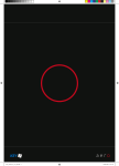
CONVI User and Service Manual Visco Probe 10100gb_7 05-08-2015 Page 1 CONVI ApS - DK 5270 Odense N – Tel. +45 6618 2026 – Fax +45 6618 2043 – e-mail : [email protected] CONVI User and Service Manual Visco Probe 10100gb_7 05-08-2015 Page 2 CONVI CONVI ApS - DK 5270 Odense N – Tel. +45 6618 2026 – Fax +45 6618 2043 – e-mail : [email protected] User and Service Manual CONVI Visco Probe 10100gb_7 05-08-2015 Page 3 Declaration of conformity Manufacturer: Convi ApS Louisevænget 7, 5270 Odense N, Denmark hereby declares under its sole responsibility that Product: Visco Probe 1 version 3 including its components, probe, base and connection box, to which this declaration refers, conforms to the relevant standards or other standardising documents. Standards and documents: Directive 1999/5/EC. Odense Niels H. Nielsen Managing Director Date: Signature: CONVI ApS - DK 5270 Odense N – Tel. +45 6618 2026 – Fax +45 6618 2043 – e-mail : [email protected] CONVI ApS - DK 5270 Odense N – Tel. +45 6618 2026 – Fax +45 6618 2043 – e-mail : [email protected] CONVI User and Service Manual Visco Probe 10100gb_7 05-08-2015 Page 4 CONVI ApS - DK 5270 Odense N – Tel. +45 6618 2026 – Fax +45 6618 2043 – e-mail : [email protected] CONVI User and Service Manual Visco Probe 1. 10100gb_7 05-08-2015 Page 5 INFORMATION ........................................................................................................................ 7 A. B. INTRODUCTION ......................................................................................................................... 7 TYPE PLATE AND APPROVAL CERTIFICATE SIGNAGE .................................................................. 7 2. SAFETY INSTRUCTIONS ...................................................................................................... 8 3. SPECIFICATIONS.................................................................................................................... 9 A. B. 4. APPLICATION ............................................................................................................................ 9 DIMENSIONS ............................................................................................................................. 9 i. Probe .................................................................................................................................... 9 ii. Base .................................................................................................................................... 10 DESCRIPTION ........................................................................................................................ 10 A. B. 5. PROBE ..................................................................................................................................... 10 BASE ....................................................................................................................................... 11 INSTALLATION ..................................................................................................................... 11 A. B. RECEIPT .................................................................................................................................. 11 PLACEMENT OF PROBE ............................................................................................................ 12 i. In planetary mixers ............................................................................................................ 12 ii. In turbine mixers ................................................................................................................ 13 C. INSTALLATION IN/ON MIXER ................................................................................................... 14 i. Probe .................................................................................................................................. 14 ii. Base .................................................................................................................................... 14 D. CONNECTION .......................................................................................................................... 15 6. DISMANTLING AND DISPOSAL ........................................................................................ 16 7. MAINTENANCE ..................................................................................................................... 16 A. B. C. D. E. 8. CLEANING ............................................................................................................................... 16 CHANGE OF BATTERY.............................................................................................................. 16 CHECK OF MEASURING SYSTEM............................................................................................... 17 CHANGE OF PROBE BALL AND PROBE ARM .............................................................................. 17 REPLACEMENT OF PROBES AND BASES ................................................................................... 18 TROUBLESHOOTING .......................................................................................................... 18 A. B. C. D. 9. SUDDEN DEVIATIONS IN THE MEASUREMENT RESULTS ............................................................ 18 NO MEASUREMENTS ................................................................................................................ 19 STILL NO MEASUREMENTS ...................................................................................................... 19 RESETTING THE BASE AND PROBE TO DEFAULT ...................................................................... 20 i. Resetting the Base .............................................................................................................. 20 ii. Resetting the Probe ............................................................................................................ 21 INSTALLATION OF PROGRAM ........................................................................................ 22 10. SETUP OF SYSTEM ON PC ................................................................................................. 22 A. B. INTRODUCTION ....................................................................................................................... 22 USER INTERFACE ..................................................................................................................... 23 CONVI ApS - DK 5270 Odense N – Tel. +45 6618 2026 – Fax +45 6618 2043 – e-mail : [email protected] CONVI User and Service Manual Visco Probe C. D. E. F. G. H. 10100gb_7 05-08-2015 Page 6 SHORTCUT TO “CONVIS.EXE” ................................................................................................. 24 START/STOP MEASURING ......................................................................................................... 24 BATCH SIZE ............................................................................................................................. 24 STATUS INFORMATION ............................................................................................................ 25 MIX DESIGNS .......................................................................................................................... 25 CLOSING OF PROGRAM ............................................................................................................ 26 11. SETUP OF LOG SYSTEM ..................................................................................................... 27 12. SETUP OF BASE ..................................................................................................................... 28 13. SETUP OF PROBE ................................................................................................................. 30 14. SETUP OF OTHER VALUES ............................................................................................... 32 15. OTHER ITEMS IN THE DROP-DOWN MENU................................................................. 33 A. B. C. D. TEST MIX................................................................................................................................. 33 BATCH CORRECTION ............................................................................................................... 33 SLUMP..................................................................................................................................... 33 TEMPERATURE ........................................................................................................................ 34 16. SETUP OF SYSTEMS OF COORDINATES ....................................................................... 34 17. ADJUSTMENT DURING DAILY OPERATION ................................................................ 35 APPENDIX 1 .................................................................................................................................... 36 COMMISSIONING WITH PROCESS CONTROL SYSTEM SK600 FROM SKAKO A/S ............................. 36 APPENDIX 2 .................................................................................................................................... 39 COMMISSIONING WITH PROCESS CONTROL MIXODATAMAT FROM HAARUP MASKINFABRIK A/S ... 39 APPENDIX 3..................................................................................................................................... 43 AUTOMATIC REGULATION OF PLASTICISER ..................................................................................... 43 ADJUSTMENT DURING DAILY OPERATION ........................................................................................ 44 CONVI ApS - DK 5270 Odense N – Tel. +45 6618 2026 – Fax +45 6618 2043 – e-mail : [email protected] CONVI User and Service Manual Visco Probe 1. 10100gb_7 05-08-2015 Page 7 Information a. Introduction This user and service manual for the CONVI viscosity meter is intended for everyone working with the equipment: operators, cleaning personnel and service and maintenance personnel. It is important that the user and service manual is read carefully and that advice and directions about safety, operation and maintenance are followed in order to ensure that the measuring equipment is used in the best possible way. It is the responsibility of the Purchaser to ensure that operators, cleaning personnel and service and maintenance personnel have read and understood the parts of this user and service manual important to their specific work with the equipment. In addition, it is the responsibility of the Purchaser to ensure that all personnel working with the measuring equipment have the necessary training to carry out the tasks required. For further information please contact CONVI ApS. b. Type plate and approval certificate signage The type plate and the sign with the FCC ID on the Probe are placed behind the battery. The type plate and the sign on the Base are placed between the fixing bolts. Fig. 1 In order to facilitate any contact and avoid misunderstandings, please quote the specifications on the type plate when you contact CONVI ApS about the measuring equipment. 0X-00Y y./No CE Type B/S 00Z CONVI ApS DK-5270 Odense N FCC ID: XXX-YYYW-WZSSS CONVI ApS DK-5270 Odense N Fig.2 CONVI ApS - DK 5270 Odense N – Tel. +45 6618 2026 – Fax +45 6618 2043 – e-mail : [email protected] CONVI User and Service Manual Visco Probe 10100gb_7 05-08-2015 Page 8 The sign containing information about compliance with part 15 of the FCC Rules is shown below. The sign is not placed on the product because of the product’s operating environment. This device complies with part 15 of the FCC Rules. Operation is subject to the following two conditions: (1) This device may not cause harmful interference, and (2) this device must accept any interference received, including interference that may cause undesired operation. 2. Safety instructions There is no safety risk connected with the transport, installation, use or maintenance of the measuring equipment. Note: This equipment has been tested and found to comply with the limits for a Class B digital device, pursuant to part 15 of the FCC Rules. These limits are designed to provide reasonable protection against harmful interference in a residential installation. This equipment generates, uses and can radiate radio frequency energy and, if not installed and used in accordance with the instructions, may cause harmful interference to radio communications. However, there is no guarantee that interference will not occur in a particular installation. If this equipment does cause harmful interference to radio or television reception, which can be determined by turning the equipment off and on, the user is encouraged to try to correct the interference by one or more of the following measures: —Redirect or relocate the receiving antenna. —Increase the separation between the equipment and receiver. —Connect the equipment to an outlet on a circuit different from that to which the receiver is connected. —Consult the dealer or an experienced radio/TV technician for help. Changes or modifications not expressly approved by the party responsible for compliance could void the user’s authority to operate the equipment. We strongly advise that the safety instructions given for the machine on which the equipment is mounted be followed in connection with installation and maintenance. CONVI disclaims any responsibility for damage occurring as a result of the directions of this manual not being followed. It is the responsibility of the Purchaser to check continuously that calibration and measuring are correct in relation to the result desired. CONVI ApS - DK 5270 Odense N – Tel. +45 6618 2026 – Fax +45 6618 2043 – e-mail : [email protected] CONVI User and Service Manual Visco Probe 3. 10100gb_7 05-08-2015 Page 9 Specifications a. Application The Convi Visco Probe is designed for measuring the viscosity of Newton liquids and materials that are partly liquid and follow the Bingham model. The Visco Probe may not applied in connection with i. Hot materials exceeding 60C. ii. Combustibles or explosives. iii. Food. In the event of any doubt, contact CONVI ApS. b. Dimensions i. Probe Fig. 3 If incorporation of the Visco Probe with the indicated standard probe length is not possible, a special version with an adjusted probe length can be supplied. CONVI ApS - DK 5270 Odense N – Tel. +45 6618 2026 – Fax +45 6618 2043 – e-mail : [email protected] CONVI User and Service Manual 10100gb_7 05-08-2015 Page 10 Visco Probe ii. Base Fig. 4 4. Description The Visco Probe mainly consists of two parts: A Probe to be mounted on the rotating parts of the mixer and a Base to be mounted on the outside of the mixer. (See the scope of delivery in the section entitled “Installation”). a. Probe The Probe is shown in Fig. 5 and consists of the indicated main components. Fixing yoke Fastening arm Probe housing Print holder Battery Probe arm Ball Fig. 5 CONVI ApS - DK 5270 Odense N – Tel. +45 6618 2026 – Fax +45 6618 2043 – e-mail : [email protected] CONVI User and Service Manual Visco Probe 10100gb_7 05-08-2015 Page 11 The rechargeable battery supplies power to the Probe. When in use, the measuring probe is moved in the concrete and exposed to a force. The force on the Probe is measured and registered by the electronics in the probe housing. The registered measured data are processed by the Probe’s software and transmitted to the Base by means of radio signals. b. Base The base is shown in Fig. 4 and contains electronics with software to receive the radio signals with the measured data from the Probe and transmit them to a PC through a cable. 5. Installation a. Receipt Upon receipt of the Visco Probe and before installation start, the contents of the consignment must be checked for any deficiencies, transport damage or any other visible defects. A system for installation on a planetary mixer is supplied as shown in the photo below and must include the parts mentioned. Battery replacement tool Fastening arm Charger Base Steel wire Magnet Battery Probe User Manual USB cable Power cable CDR Cable to reset probe Connection box CONVI ApS - DK 5270 Odense N – Tel. +45 6618 2026 – Fax +45 6618 2043 – e-mail : [email protected] CONVI User and Service Manual 10100gb_7 05-08-2015 Page 12 Visco Probe Fig. 6 The CD-R contains the program for the PC and the user manual. If the system is to be installed on a turbine mixer, the consignment will include two Probes and two fastening arms. b. Placement of Probe i. In planetary mixers The fastening arm supplied (square steel 30x30 mm) is welded onto the mixer star and placed 50 mm behind and parallel with the radius on which the Probe is to be placed. See Fig. 7. In order to achieve the correct placement of the square steel adjustment it is necessary to adapt it, and it can be necessary to make an extension to the mixer star of a piece of strong plate and weld the fastening arm to this extension. Welding must be performed by skilled personnel, because inadequate welding can result in the Probe falling off and being damaged, and perhaps inflicting damage on the mixer or machines later in the process. Direction of motion Strong plate Centre of mixer star 50 R Calculated radius Fig. 7 NOTE: The square steel is mounted in an upright position and must be placed horizontally. Placement above the mixer bottom must comply with dimension sketch, Fig. 3. CONVI ApS - DK 5270 Odense N – Tel. +45 6618 2026 – Fax +45 6618 2043 – e-mail : [email protected] CONVI User and Service Manual Visco Probe 10100gb_7 05-08-2015 Page 13 The Probe is placed in front of a mixer shovel at a distance of ¼ - 1/3 of the distance to the shovel in front and in a radius “R” from the centre of the mixer star to the centre of the Probe. R is determined as follows. The Probe must be positioned in the concrete all the time when the measurements are made. It must not move into areas where the shovel in front has removed the concrete. The aim is to have a ratio between max. and min. speed of the Probe of between 1.6 and 3 to 1. In order to be able to calculate the radius that satisfies this ratio, you must either know or measure the following: C [m] = distance in metres from centre of mixer to centre of mixer star n1 [rpm] = Number of revolutions of gear bottom/side scraper n2 [rpm] = Number of revolutions of the mixer star in relation to the gear bottom K 1 n1 [metre], where K is selected in the area of 1.6 to 3, C K 1 n1 n2 so that radius R fits the space in the mixer and the above requirements as well as possible. Radius R [m] = It is important to check that the Probe does not collide with the mixing tools when the mixer is put into operation! In connection with the installation of the program on the PC, the max. and min. speeds of the Probe must be applied. The speeds are calculated as follows: Max. speed Vmax. [m/sec.] = 2 ( n2xR + n1(C+R)) 60 Min. speed Vmin. [m/sec.] = 2 (n2xR -n1(C-R)) 60 ii. In turbine mixers In this type of mixer two Probes are mounted. The two Probes are mounted on the rotating part in their respective radius from the mixer centre. See Fig. 8. The fastening arm supplied (square steel 30x30 mm) is welded on, for example, a scraper arm 50 mm behind and parallel with the radius on which the Probe is to be placed. See Fig. 8. Adjustment is required to achieve the correct placement of the fastening arm and it can be necessary to make an extension of a strong plate and weld the fastening arm onto this extension. Welding must be carried out by skilled personnel, because insufficient welding can result in the Probe falling off and being damaged, and perhaps inflicting damage on the mixer or machines later in the process. The Probes must be placed so that there is clearance of 100 mm from the pan side and the centre pipe. CONVI ApS - DK 5270 Odense N – Tel. +45 6618 2026 – Fax +45 6618 2043 – e-mail : [email protected] CONVI User and Service Manual 10100gb_7 05-08-2015 Page 14 Visco Probe Direction of motion Pan side 50 Radius in mixer Centre pipe Fig. 8 NOTE: The square steel is mounted in upright position and must be placed horizontally. Placement above the mixer bottom must comply with dimension sketch, Fig. 3. The Probes must be placed in front of a mixing shovel at a distance of 1/4 to 1/3 of the distance from the shovel at the front. c. Installation in/on mixer i. Probe The Probe is tightened to the fastening arm so that it is placed in the correct radius and points in relation to the direction of motion as shown in Figs. 7 and 8 respectively. The bolts are lubricated with grease and tightened to a torque of 160 Nm. ii. Base The Base is mounted on the outside of the mixer cover in an area where it does not disturb the operation and where there is a clear view from the Base to the Probe. The Base should not be placed immediately next to the cement inlet. One hole with a diameter of 95 mm is cut in the cover and the welding flange supplied is placed on top of the cover, in line with the cut hole. The flange is welded 25%. Upon completion of welding and cooling, the Base is bolted onto the welding flange. If possible, the Base should be placed in such a way that connections are facing downwards to reduce the risk of moisture penetration. CONVI ApS - DK 5270 Odense N – Tel. +45 6618 2026 – Fax +45 6618 2043 – e-mail : [email protected] CONVI User and Service Manual Visco Probe d. 10100gb_7 05-08-2015 Page 15 Connection Connection of the Base to the Connecting box is made by means of a screened twisted pair network cable type: CAT5e 4x2x0.51 mm AWG24 S-FTP. The cable has RJ45 plugs with screens. Both plugs should be fitted as specified. When the plug is viewed from the cable inlet and the latch is turned downwards, the wiring sequence must be: Left side Right side 1 2 3 4 5 6 7 8 white/orange orange white/green blue white/blue green white/brown brown NB! Incorrect connection can damage the Base’s PCB. The Base cover is unscrewed using the key supplied and the cable is fed into the Base before the plug is fitted. The cable is connected to one of the two plugs on the PCB. If the system has several Bases, the Bases are connected in series by connecting the second plug of the Base to the following Base, etc. If there are several Bases in series, the jumper which is placed on the PCB immediately beneath the connection plugs must be removed, except on the last Base of the series. When the network cable has been tightened suitably, the union is fastened on the cable gland and the cover is screwed onto the Base. The connecting box supplied is placed by the PC and connected to 230V power supply and the network cable from the Base is connected. The connecting box is connected to the PC with the USB cable supplied. The system is EMC-tested and approved with the cable supplied. The cable must therefore not be replaced or lengthened. A driver that sets up the USB connection to work with the system is installed from the CD-R in the connecting box or via the Internet. When the driver is installed, the USB connection is assigned a COM port number, which must be used when setting up the system (see section 12). Install the software on the PC as described in the instructions, section 9. Change the battery in the Probe (see section “Change of battery”). CONVI ApS - DK 5270 Odense N – Tel. +45 6618 2026 – Fax +45 6618 2043 – e-mail : [email protected] CONVI User and Service Manual Visco Probe 10100gb_7 05-08-2015 Page 16 Install PC program as described in the instructions, section 10. Check the measured value as stated in the section “Check of measuring system”. 6. Dismantling and disposal Dismantling of the Probe takes place by loosening the two M16 bolts on the fixing yoke and pulling the Probe over the end of the fastening arm. If the fastening arm is also to be removed, it must be cut off by means of an angle grinder or a cutting burner. Dismantling of the Base takes place by dismantling the six M6 hexagonal screws. If the Base is not to be mounted again, the hole in the mixer cover must be closed to avoid dust emission. Disposal of the parts must take place in accordance with the local rules valid at any time. In order to carry out an environmentally correct disposal, it can be noted that the viscosity meter consists of steel, electronic components, batteries and plastic material of the types PA, PEHD and PEEK. Batteries and electronic components must be returned to CONVI ApS. 7. Maintenance a. Cleaning The Probe must be cleaned completely once every 8 hours of operation. Remove all concrete from probe ball, probe arm and probe housing. Avoid exaggerated use of the high-pressure cleaner on the probe housing. The Base must be cleaned daily on the surface inside the mixer. On the outside of the mixer the Base must be cleaned once a week. Attention to network cable is required and exaggerated use of high-pressure cleaner should be avoided. b. Change of battery The battery must be changed when the system reports “Battery low” (see section 10.e). The most reliable way of controlling the battery change is to replace it at regular intervals. The battery service life is 1 to 2 weeks. CONVI ApS - DK 5270 Odense N – Tel. +45 6618 2026 – Fax +45 6618 2043 – e-mail : [email protected] CONVI User and Service Manual Visco Probe 10100gb_7 05-08-2015 Page 17 The battery is dismantled by means of the special key supplied. Remove any dirt in the thread and on the two contact surfaces and tighten the battery manually or with a very light pull of the special key. Connect the battery that is not in use to the charger. The charger switches automatically to maintenance charging when charging is complete. This means that it is not necessary to disconnect the charge. The safest way to dispose of old batteries is to return the old batteries to CONVI ApS, who will then assume responsibility for disposal taking place in accordance with current rules and regulations. c. Check of measuring system The sensitivity of the measuring system is checked prior to delivery. After installation, the display should be checked at a known weight (3 – 5 kg). Suspend the weight on the Probe as shown in Fig. 9. Start the measuring system (see section 10.d). Read the yield stress. Wire Key Weight Fig. 9 Remove the weight again and read the yield stress again. Register and save the two measurements as well as the weight! The registered values should be checked once every other month. d. Change of probe ball and probe arm When the probe ball is worn, i.e. the smallest diameter is 95 mm, it must be changed to avoid unacceptable measurement deviations. The probe arm must be replaced if its smallest diameter is under 25 mm. CONVI ApS - DK 5270 Odense N – Tel. +45 6618 2026 – Fax +45 6618 2043 – e-mail : [email protected] CONVI User and Service Manual Visco Probe 10100gb_7 05-08-2015 Page 18 Unscrew the probe ball using a pipe wrench, clean the end of the probe arm and apply grease to the thread and re-tighten the probe ball using a 10 mm Allen key (torque 81 Nm). Unscrew the probe arm from the probe housing using a 27 mm fork wrench or a pipe wrench. Remove concrete from the area on the underside of the probe housing. Clean and lubricate the thread. The probe arm is screwed and tightened using a torque wrench mounted with a 27 mm fork wrench. Tighten the probe arm to a torque of 330 Nm. The incorrect torque can result in damage to the measuring shaft in the probe housing. After installing the probe arm and probe ball, perform a zero point adjustment (see ‘Setup of Probe’), and check the display by means of a control weighing (see “Check of measuring equipment”). e. Replacement of Probes and Bases When delivered, Probes and Bases are set to address 0. If the system has only one Base and one Probe, replacement can take place without any change of the base address. For systems with more Bases and/or Probes, base addresses different from 0 are used for all systems so that they all transmit at different frequencies without disturbing one another. Read also the section entitled “Setup of Base”. A new Probe is always set to address 0. A change to a real address takes place from the PC by opening the tab for the relevant Probe and clicking “Reset”. This enables the system to find the Probe itself and adjust the address. Then press ‘Send’ and perform a zero point adjustment (see ‘Probe setup’). A new Base is always set to address 0. A change to a real address takes place from the PC by opening the tab of the relevant Base and making it show the setup for Base 0. The Base address is then changed to the actual address and “Send” is activated. The same procedure is applied for a change of a complete system or the installation of a new system. When new systems in the series are set up they must be connected to the power supply one at a time, and the setup of the base address for each system must be completed before the next system is connected. 8. Troubleshooting a. Sudden deviations in the measurement results Check that probe arm and probe ball are intact. Check the daily cleaning process. CONVI ApS - DK 5270 Odense N – Tel. +45 6618 2026 – Fax +45 6618 2043 – e-mail : [email protected] CONVI User and Service Manual Visco Probe 10100gb_7 05-08-2015 Page 19 Check and perform a zero point adjustment of the Probe if necessary (see section 12). Carry out control weighing (see section 7.c). b. No measurements Click the start button and click again if the text on the button says “Start measuring”. c. Still no measurements 1. Go into the setup under Base and press “Receive”. Check the status information (see section 12). If the status is displayed as ……“Base – OK”…….. go to 2, If the status is not displayed as ….. Base – OK …….. : Check that the power supply to the connecting box is switched on. Check that the cable from the connecting box is inserted correctly in the PC. Check that the cable between the connecting box and the Base on the mixer has not been damaged. If no error is found and corrected, close the CONVI program on the PC and switch off the power supply to the connecting box. After a short while, switch on the power supply to the connecting box again and restart the CONVI program on the PC. If the status is not now displayed as …. Base – OK ….., continue from section d. 2. If the status is displayed as …. “Base – OK – Probe – OK”…, the system is ready for use. If it is not, change to the “Probe” tab and press “Reset” followed by “Receive”. If the status is not displayed as ….. “Probe – OK” ……..: Check if the battery has been charged, and, if necessary, replace it with the battery in the charger. If the status is still not displayed as ….. “Probe – OK” …….., the entire system is to be closed down completely. This is done by removing the battery on the Probe, switching off the power supply to the Base and closing the CONVI program on the PC. Soon after the power supply to the connecting box is switched on again, the battery is replaced on the Probe and the CONVI program is restarted. If the status is not constantly displayed as ….. “Probe – OK” …….., press “Reset” followed by “Receive”. If the status is not now displayed as …. “Probe – OK” ….., continue from section d. CONVI ApS - DK 5270 Odense N – Tel. +45 6618 2026 – Fax +45 6618 2043 – e-mail : [email protected] CONVI 10100gb_7 05-08-2015 User and Service Manual Page 20 Visco Probe d. Resetting the Base and Probe to default i. Resetting the Base On the PC, open the program for the system you want to reset. 1) Set “Show setup for base” to “0” 1 2 3 Status field Use the Magnet to reset the Base. This is done by holding down the Magnet for approx. 5 seconds to the bottom of the right-hand side of the PCB as viewed from the cable inlet. Push the Magnet down using a screwdriver, for example. 2) Press the “Reset” button. The system will now display ….. “Base – OK” ……..in the status field. If the system does not display ….“Probe 1 – OK”…., reset the Probe as described below. 3) When the status of both the Base and the Probe are displayed as OK, change the base address to the address required. This is done by selecting the address number in “Base address” and then pressing “Send” and “Receive”. CONVI ApS - DK 5270 Odense N – Tel. +45 6618 2026 – Fax +45 6618 2043 – e-mail : [email protected] CONVI User and Service Manual Visco Probe 10100gb_7 05-08-2015 Page 21 ii. Resetting the Probe On the PC, open the program for the system for which you want to reset the Probe and then switch to the “Probe 1” tab. 1) Remove the battery in the Probe and use the wire supplied to connect the battery to the Probe. The poles must be correctly connected, that is, the centre of the battery to the centre of the Probe, otherwise the Probe’s PCB will be damaged. Probe Screw head Magnet Centre of Probe Centre of battery Battery 2) Place the magnet supplied as shown and move it slowly back and forth between the 2 upper screw heads for approx. 5 seconds. 4) Remove the magnet and wires from the Probe. 5) Fit the Probe’s battery. Use your hands to stretch it or lift it with the tool supplied. 6) Press the “Reset” button. 7) Press “Receive” followed by “Send”. If the status is not now displayed as…. “Probe 1 – OK” ….., note down the system error message and contact Convi ApS. CONVI ApS - DK 5270 Odense N – Tel. +45 6618 2026 – Fax +45 6618 2043 – e-mail : [email protected] CONVI User and Service Manual Visco Probe 9. 10100gb_7 05-08-2015 Page 22 Installation of program The program is available on the supplied CD-R in one folder called Convi. The folder “Convi” is to be copied onto the hard disk of the PC under C:\ or under C:\Program Files\. Open the folder. For Windows 7 and 8, the files ‘Convis program’ and ‘Conviserver program’ must be selected in ‘Run this program as administrator’. Right-click on the file and select Properties, then select compatibility and confirm the selection. Then double-click “RegServer.bat” in order to register the driver. Program is started by double-clicking “convis.exe”. This file can advantageously be placed on the desktop. When the program has started, first select COM port and base address (see section 12). 10. a. Setup of system on PC Introduction The software supplied is a program for setup of Base and Probe(s) for consistency measuring in a concrete mixer. The Probe mounted in the mixer constantly measures the force exerted on the measuring probe when rotating in the mixer, meeting resistance from the concrete. The force on the measuring probe is measured at two different speeds. Mounted on the measuring probe is a PCB, which is supplied with voltage from a mounted battery. The Probe transfers the measured results wirelessly to the Base fixed on the upper side of the mixer. From the Base, the measured results can be collected on a PC by means of a RS485 connection. The program shows measured results on an ongoing basis in three systems of coordinates. CONVI ApS - DK 5270 Odense N – Tel. +45 6618 2026 – Fax +45 6618 2043 – e-mail : [email protected] CONVI User and Service Manual Visco Probe b. 10100gb_7 05-08-2015 Page 23 User interface The system of coordinates in the upper left-hand corner shows the measured results of the two speeds on an ongoing basis. The system of coordinates in the upper right-hand corner shows the current measurement translated into a line with yield stress as function of probe speed. Boundary lines are also displayed on the basis of the max. deviations entered (lower right-hand corner). The values matching the two measuring speeds are marked on the x-axis. The system of coordinates in the lower left-hand corner shows yield stress as function of viscosity. This displays the current measured result as a point. The boundaries are also displayed as a “box” on the basis of the max. deviations entered. When the current values are within the max. deviations, the area is green, otherwise it is red. At the top of this system of coordinates, the current numerical values are also displayed for viscosity and yield stress respectively as well as slump/slump flow and concrete temperature, if the system is set up for this (see see section 15). CONVI ApS - DK 5270 Odense N – Tel. +45 6618 2026 – Fax +45 6618 2043 – e-mail : [email protected] CONVI User and Service Manual Visco Probe c. 10100gb_7 05-08-2015 Page 24 Shortcut to “ConVis.exe” As well as providing easy access to the program, the shortcut can also be used to ensure that the program always starts with the correct base address and to specify which mixer it responds to. Right-click on the shortcut and select “Properties’, place the cursor immediately after the given path in the “Destination” line, insert a space and then type “base address”, insert a space and then type “mixer name”. The mixer name must not contain spaces. Press OK and start the program. You can now see the mixer name at the top of the user interface after “Visco Probe”. d. Start/stop measuring Click “Start measuring” and receipt of data from the Probe will be started and the systems of coordinates will be updated currently. At the same time the current measured values are logged in the file “RcvValue.Log” . Click “Comments” and the following display will appear: A comment can be entered in this field, e.g. “Added 10 litres of water” or the like. This comment will then be recorded in the log file “RcvValue.log”, i.e. these comments will then be available for a later analysis of the log file, if required. When you have clicked the “Start measuring” button, the button text will change to “Stop measuring”. If the “Stop measuring” button is activated, receipt of data will stop. e. Batch size This field is only used if the system is running together with Viscolone. If this is the case, the current batch size is entered here. CONVI ApS - DK 5270 Odense N – Tel. +45 6618 2026 – Fax +45 6618 2043 – e-mail : [email protected] CONVI User and Service Manual Visco Probe f. 10100gb_7 05-08-2015 Page 25 Status information In the status field the status of the Probe is displayed as: “OK” or “Battery low” or a possible error message. In the field “Actual values” number and name of the selected mix design are displayed. The target values entered for this mix design for viscosity and yield stress and max. deviations are also displayed. g. Mix designs If you click the “Mix design” button, the following window will appear: This window is used to set up mix designs during manual operation and during automatic operation with Visco Control and Viscolone. Here the mix design is selected according to which production is to take place. The selection takes place by first clicking the number of the required mix design and then clicking the “OK” button. New mix designs can be created or the actual values of the created mix designs can be changed. CONVI ApS - DK 5270 Odense N – Tel. +45 6618 2026 – Fax +45 6618 2043 – e-mail : [email protected] CONVI User and Service Manual Visco Probe 10100gb_7 05-08-2015 Page 26 A new mix design is created by clicking the “New” button. The fields now become white and new values can be entered. When the entering has been completed, click the “Save” button and then the “OK” button. The values of an existing mix design can be changed by clicking “Change”. The fields now become white and the values can be changed as required. When the changes have been completed, click the “Save” button and then the “OK” button. The other entry fields are only used during automatic operation with Visco Control or Viscolone. Refer to the manual for the system in question for further information. A mix design can be deleted by marking the actual mix design number and then clicking the “Delete” button. h. Closing of program Before the program is closed, the measurements must be stopped. Closing takes place by clicking the “Close” button. CONVI ApS - DK 5270 Odense N – Tel. +45 6618 2026 – Fax +45 6618 2043 – e-mail : [email protected] CONVI User and Service Manual Visco Probe 11. 10100gb_7 05-08-2015 Page 27 Setup of log system Click on the CONVI icon in the upper left corner and select “Log setup” and the following display will appear: In normal operation, the setup should be as shown in the above screenshot. Simulation of the system is selected by marking the field next to “Simulation” and the system is taken out of simulation by removing the marking. By clicking on “Simulation file” you can select the file that contains the course you want to simulate. “Value Ex” log files from real operations can be used for simulation. Data from the “Value Ex” file is loaded and applied instead of the data from the measuring system. If “Simulation” is selected, measured data from the selected log file will be loaded and a course can be displayed without the Probe being affected by concrete. If the COM port under setup is set at “None” at the same time, simulation can take place without any measuring system being connected. If only “Simulation” is selected but COM port has been set to a concrete port and measuring system has been connected, only measured data will be simulated. Parameter setup will be applied from the connected measuring system. Using list boxes, “Serial log level” and “Received data” can be selected to be “All”, “In case of error” or “None”. Unless otherwise agreed with CONVI ApS, both values are set at “All”. The field next to “Check sum” must always be selected! CONVI ApS - DK 5270 Odense N – Tel. +45 6618 2026 – Fax +45 6618 2043 – e-mail : [email protected] CONVI User and Service Manual Visco Probe 12. 10100gb_7 05-08-2015 Page 28 Setup of Base If you click the CONVI icon in the upper left corner and select Setup, the following setup display will appear: Under “Communication port” the COM port is selected to which the system is connected. You can find the number by right-clicking on “My Computer” on your desktop and selecting “Manage”. On the left, select “Device Manager”; on the righthand, side open the item “Ports”. Here you can see which COM port number has been assigned to the system. If COM port is selected as “None”, the program will run in demo mode, making demonstration without connected Probes possible. Under “Show setup for base”, the address of the Base is selected with which communication is required. If it is a new base, address 0 is selected, as new bases always have the address 0. If you click “Receive”, current parameters are retrieved from the Base and displayed in the grey fields. Other values can be selected using list boxes, and if you click “Send” these values will be transmitted to the Base. Immediately afterwards parameters will be retrieved to the grey fields so that you can see that they have been transferred. The current status of the latest command is displayed at the bottom of the display. CONVI ApS - DK 5270 Odense N – Tel. +45 6618 2026 – Fax +45 6618 2043 – e-mail : [email protected] CONVI User and Service Manual Visco Probe 10100gb_7 05-08-2015 Page 29 The version of the software in the base print is displayed in the version field. In connection with a new base address, the base address is changed to this value and after “Send” has been selected and the address changed, the “Show setup for Base” field is updated automatically to the new address. In the “Number of probes” field, the number of probes connected to the Base is indicated, either 1 or 2. In the “Base address” field, select the address for the system. Then press “Send”. The system address is changed and the “Show setup for base” field automatically changes to the new address. Under data type, selection between “Normal”, “Test” or “Filtered test” is possible. Always select “Normal”. The other two setups are only to be applied by CONVI or together with CONVI in connection with a system test. The voltage supply to the Base is displayed in the “Voltage (Ext)” field, and the regulated internal voltage supply to the Base is displayed in the “Voltage (Int)” field. In connection with the selection of the number of probes (1 or 2), pages will appear for the selection of parameters for Probes. CONVI ApS - DK 5270 Odense N – Tel. +45 6618 2026 – Fax +45 6618 2043 – e-mail : [email protected] CONVI User and Service Manual Visco Probe 13. 10100gb_7 05-08-2015 Page 30 Setup of Probe Click on the tab of the Probe for which setup is required. The version of the software in the probe print is displayed in the version field. In the “Zeropoint” field, 2 values must be entered to tare the Probe to a required starting value. This is done by checking the value in the “Strain value” Field. When the Probe is unloaded, this value will be within the range 190 – 210. The setting is defined automatically by activating the “Auto offset” button. If the zero displacement does not show identical values in the grey and white fields, “Auto offset” must be reactivated. If a taring is to be made subsequently, this is done by clicking on the CONVI icon in the upper left-hand corner and selecting “Zeropoint”. In the box displayed, see below, probe number must be selected, whereupon the “Auto offset” button is activated followed by activation of “OK”. For taring, the mixer must be stopped and the Probe must be clean. CONVI ApS - DK 5270 Odense N – Tel. +45 6618 2026 – Fax +45 6618 2043 – e-mail : [email protected] CONVI User and Service Manual Visco Probe 10100gb_7 05-08-2015 Page 31 Enter how much the signal from the Probe is to be gained in the “Gain” field. Low values equal high gain. The gain is adjusted so that the “Strain value” does not exceed 4,000 at max. load on the Probe. Usually this requires a setting between 1 and 4. In the “Period time” field, the revolution time of the arm is indicated on which the Probe is mounted. The time is indicated in 1/10 seconds, i.e. the number 20 corresponds to 2 sec. In the “Allow deactivation” field, indicate by selecting if the Probe is allowed to go into hibernation mode automatically and save battery consumption. The value specified is the difference required between max. and min. impact on the Probe to bring it out of hibernation mode again. Usually a value of 5 will ensure that the Probe goes into hibernation mode when the mixer is stopped. A higher value will extend the life of the battery. However, the value should not be so high that the Probe goes into hibernation mode during the mixing process. The ‘Temperature’ row shows the internal temperature in the Probe in the first field. The second field contains a measurement value of the concrete’s temperature, and the concrete’s temperature is shown in the third field. The “Strain value” field shows the current load of the Probe expressed as a value between 0 and 4096. The “Strain voltage” field shows the voltage supply to the measuring system. The “Voltage (Ext)” field shows the voltage of the battery supply and the “Voltage (Int)” field shows the voltage after the internal regulation. When “Voltage (Ext)” comes close to the value of “Voltage (Int)”, the battery must be replaced. New values can be sent to the Probe by entering the new values in the white fields and clicking “Send”. Click “Receive” and all values will be updated to the current values of the Probe. Click “Reset” and Base and Probe will be reset, but both will keep the preset parameters. CONVI ApS - DK 5270 Odense N – Tel. +45 6618 2026 – Fax +45 6618 2043 – e-mail : [email protected] CONVI User and Service Manual Visco Probe 10100gb_7 05-08-2015 Page 32 Click “Reset to default” and Base and Probe will be reset, and all values will be reset to the standard setups. Click “Deactivate probe” and the Probe will go into hibernation mode and save battery life. Click “Activate probe” and the Probe will wake up from hibernation mode (this takes approx. 15 seconds). Click “Send” or “Receive” and the parameters from all setup pages will be transferred as a whole. 14. Setup of other values Under the “Misc.” tab, values are entered that are applied by the program in connection with the display of measurements. These values are not transferred to Bases and Probes, but only applied internally for setup of graphics and scaling of the received values. None of the values in the “Misc.” tab, apart from Average 1 and 2, should be changed after commissioning. CONVI ApS - DK 5270 Odense N – Tel. +45 6618 2026 – Fax +45 6618 2043 – e-mail : [email protected] CONVI User and Service Manual Visco Probe 10100gb_7 05-08-2015 Page 33 Enter values for the low and high speed of the Probe, respectively. The speeds are calculated as shown in section 5.b. The current calculated speeds are scaled up so that the high speed is between 12 and 20. Enter the value detected for the high speed. For the low speed, enter half of the detected value. The points of speed can be seen as markings on the x-axis in the system of coordinates in the upper right-hand corner and have significance as regards the conversion of the impacts on the Probe to yield stress and viscosity respectively. Zero point adjustment and gain of signal are applied to adjust the display on the PC. “Averaging 1 over” is applied to indicate the number of measurements required in a current averaging of max. and min. measurements from the Probe, and the value of “Averaging 2 over’ is applied to indicate the number of measurements required in the current averaging of yield stress and viscosity. If high values are entered, the measurement result becomes more stable, but at the same time the response of the system becomes slower. The values should not be under 2 and not over 5. 15. Other items in the drop-down menu If you click on the CONVI icon in the top left-hand corner, you can choose between several menu items. The individual menu items are explained below. a. Test mix Read about this in Appendix 2. b. Batch correction The Probe’s measurement depends on the batch size. It is therefore necessary to correct the target values so that they match the batch size. Follow the description in Appendix 1 to find the correction values. c. Slump When you click on this item, a table appears into which associated values of the Visco Probe’s slump flow and the laboratory’s measured slump/slump flow can be entered. Enter the lowest yield stress at the top of the column. This means that the concrete with the biggest slump flow will be at the top, and the slump flow reduces as you go down the column. The lower part of the column contains the slump concretes, finishing with the concrete that has the smallest slump. When the columns have been completed, the concrete’s slump/slump flow appears in the Visco Probe’s user interface. It can be a good idea to enter the values in a spreadsheet as they are collected. These values provide a series of points that form a curve. Values from the curve can be read off at suitable intervals and inserted into the columns. CONVI ApS - DK 5270 Odense N – Tel. +45 6618 2026 – Fax +45 6618 2043 – e-mail : [email protected] CONVI User and Service Manual Visco Probe d. 10100gb_7 05-08-2015 Page 34 Temperature If you click on temperature, this window appears: If the Visco Probe is fitted with a temperature measurement system, you can enter 2 sets of associated values for the Visco Probe’s current measurement value and the concrete’s temperature to display the concrete temperature in the Visco Probe’s user interface. The concrete temperature is measured by a calibrated thermometer, and the current measurement value is read off under the setup on the ‘Probe 1’ page. The measurement value is the figure in the centre field in the temperature row. 16. Setup of systems of coordinates Right-click with the mouse within each of the three systems of coordinates and the following display will appear: Here the value ranges of the axis divisions can be changed at your own discretion. CONVI ApS - DK 5270 Odense N – Tel. +45 6618 2026 – Fax +45 6618 2043 – e-mail : [email protected] CONVI User and Service Manual Visco Probe 17. 10100gb_7 05-08-2015 Page 35 Adjustment during daily operation The adjustments shown below are made in the relevant process or water control system in which the set values for viscosity and yield stress are entered together with the correction per unit and tailing; those values are used to calculate the extra water required. Four situations where adjustments are necessary are listed below, as well as instructions for making the adjustments. 1. If the cross is within the acceptance range and: a. The concrete is too dry, the set value for viscosity must be decreased. b. The concrete is too wet, the set value for viscosity must be increased. 2. If the cross ends to the right of the acceptance range, the quantity of extra water must be increased. This is done by: a. Increasing the value for “Correction per unit”. b. Decreasing the value for “Tailing”. (Should only be changed after checking during test mix). 3. If the cross ends to the left of the acceptance range, the quantity of extra water must be decreased. This is done by: a. Decreasing the value for “Correction per unit”. b. Increasing the value for “Tailing”. (Should only be changed after checking during test mix). 4. If the cross ends above or below the acceptance range, the set value for yield stress is adjusted to the final value reached. CONVI ApS - DK 5270 Odense N – Tel. +45 6618 2026 – Fax +45 6618 2043 – e-mail : [email protected] CONVI User and Service Manual Visco Probe 10100gb_7 05-08-2015 Page 36 Appendix 1 Commissioning with process control system SK600 from SKAKO A/S When setup of the Visco Probe system has been completed according to the description in the manual, the commissioning in the SK600 can start. 1. Determination of values per mix design a. Time of measurement of the values applied for water calculation must be determined. Time is determined by looking at the measurement curves and the values for viscosity and yield stress during the mixing process. When the measurement curves stabilise and become almost horizontal, and when the values for viscosity and yield stress are decreasing evenly, measuring can take place. b. Final mixing time, i.e. from measuring and proportioning of additional water until the mix has been mixed completely, is selected on basis of experiences with the actual mixer and estimate of the time when the measurements of the Visco Probe are stable. c. The target values for viscosity and yield stress are registered. During normal production the measured values for viscosity and yield stress are registered simultaneously with the laboratory estimating the mixes. When there is a mix which is exactly as it should be, the values from this mix are applied as target values. (Value at full mix). d. In order to be able to calculate the water quantity which the Visco Probe is to add, two relations must be determined, i.e. tailings and sensitivity. The values are found at full batch. Full batch must be the value which is indicated in the SK600. 1. Change of viscosity and yield stress without addition of additional water must be determined. This is done by reading the values at the time of measuring and again when the mixing time expires. The difference between the two values is the tailings of the viscosity and the yield stress, respectively. 2. The sensitivity of the concrete towards water (correction per unit) must be determined. This is done by reading the viscosity at the time of measuring and adding 5 litres of water per m³ concrete. The viscosity is read again when the mixing time expires. It may be advantageous to register more mixes and apply an average. The sensitivity is now: 5/(the change at 5 litres – tailings) 2. Automatic registration of the values SK600 can perform items 1.c and 1.d automatically. This is done by selecting ‘Test mix’ in the SK600 window, where the concrete order is entered. A special cycle then runs, in which SK600 finds the values and transfers them to the mix design. CONVI ApS - DK 5270 Odense N – Tel. +45 6618 2026 – Fax +45 6618 2043 – e-mail : [email protected] CONVI User and Service Manual Visco Probe 10100gb_7 05-08-2015 Page 37 3. Batch correction The dependence on batch size is registered by mixing a whole batch so that it is close to the desired target values for consistency. If you click in the top left-hand corner in the user interface, a drop-down menu appears. If you select ‘Batch correction’ this window appears: The window is a tool to help define the batch size correction. An explanation of how to use the system also appears on an ongoing basis in the upper part of the window. Mix a full batch of a commonly used concrete. 1. When the Visco Probe’s display is stable, press ‘read’. The viscosity and yield stress are then entered into the two fields. 2. Stop the mixer and measure the concrete level in the mixer. Enter the value in the ‘Level’ field. 3. Start the mixer and empty approx. 20% of the whole mix. If more than 30% is emptied, the test cannot be performed. 4. Press ‘Next’. A new row appears. Repeat items 1 to 4 until the calculated value for the level is below 25%. If you are below 25% before the fifth measurement, the test cannot be performed. CONVI ApS - DK 5270 Odense N – Tel. +45 6618 2026 – Fax +45 6618 2043 – e-mail : [email protected] CONVI User and Service Manual Visco Probe 10100gb_7 05-08-2015 Page 38 When the above requirements are satisfied, the ‘Calculate’ button is activated when you press the ‘Next’ button. If you press ‘Calculate’, the correction values for viscosity and yield stress appear for 3/4, ½ and ¼ batch. If process control is set up for it, these values can be transferred automatically to process control by pressing ‘Transfer’. The test normally needs to be performed only once, as the values found can be used for all mix designs. 4. On basis of an estimate of the registrations under item d.2 suitable values of max. deviation +/- are selected. As a starting point, 10% of ‘Values at full mix’ can be selected. Selection of the Visco Probe and entering of the above values and other values in the mix design are performed according to instructions in the manual for the SK600. Setup of mixing cycle is also performed according to the manual for the SK600. CONVI ApS - DK 5270 Odense N – Tel. +45 6618 2026 – Fax +45 6618 2043 – e-mail : [email protected] CONVI User and Service Manual Visco Probe 10100gb_7 05-08-2015 Page 39 Appendix 2 Commissioning with process control Mixodatamat from Haarup Maskinfabrik A/S When setup of the Visco Probe system has been completed according to the description in the manual, commissioning in the Mixodamat can start. 1. Determination of values per mix design a. Time of measurement of the values applied for water calculation must be determined. Time is determined by looking at the measurement curves and the values for viscosity and yield stress during the mixing process. When the measurement curves stabilise and become almost horizontal, and when the values for viscosity and yield stress are decreasing evenly, measuring can take place. b. Final mixing time, i.e. from measuring and proportioning of additional water until the mix has been mixed completely, is selected on basis of experiences with the mixer in question and an estimate of the time when the measurements of the Visco Probe are stable. c. The target values for viscosity and yield stress are registered. During normal production the measured values for viscosity and yield stress are registered simultaneously, with the laboratory estimating the mixes. When there is a mix which is exactly as it should be, the values from this mix are applied as target values. (Ac. to quick and Yield strength). d. In order to be able to calculate the water quantity which the Visco Probe must add, two relations must be determined, i.e. tailings and sensitivity. These values are found at full batch. Full batch must be the value indicated in the Mixodatamat. 1. Change of viscosity without addition of additional water must be determined. This is done by reading the values at the time of measuring and again when the mixing time expires. The difference between the two values is “KW change without water ad” of the viscosity. It may be an advantage to register more mixes and then use an average. 2. The sensitivity of the concrete towards water (KW sensitivity at 1,000 KG) must be determined. This is done by reading the viscosity at the time of measuring and adding 2 litres of water per 1,000 kg concrete. The viscosity is read again when the mixing time expires. It may be advantageous to register more mixes and apply an average. The output sensitivity at 1,000 kg is now: 2/(the change at 2 litres – tailings) 2. Automatic registration of values The program contains a system for the automatic registration of: Time of measurement, calculated tailings and calculated correction per unit. CONVI ApS - DK 5270 Odense N – Tel. +45 6618 2026 – Fax +45 6618 2043 – e-mail : [email protected] CONVI User and Service Manual Visco Probe 10100gb_7 05-08-2015 Page 40 If you click on the CONVI icon in the upper left-hand corner and select “Test mix” the following display will appear. At the top of this display the current measured value of the system for viscosity and yield stress will appear. At the time of the cycle from where the countdown to the measuring time is to be controlled, the button “Mixing start” is to be activated. Once the measuring is stable, the button “Stable measuring” is to be activated. In this way the time from start to stable measuring as well as the measured value for viscosity at this time are registered. When the mixing time has expired, the button “Mixing completed” is to be activated and the measured value for viscosity is registered. The difference between the two viscosity measurements is shown in the field between the two measured values. If the field “Tailing” says “0”, this value will also be registered in this field. Another mix is mixed and this time 5 litres water per 1000 kg concrete are added as soon as the button “Stable measuring” is activated (the Mixodatamat works with 1000 kg and not m3). Then the total water quantity post-proportioned is to be entered as well as the size of the mix in 1000 kg. When the mixing time expires, press “Mixing completed” and the system now calculates “effective sensitivity at 1000 kg”. If tailings are already known, the value can be entered. In this case the first mix can be left out CONVI ApS - DK 5270 Odense N – Tel. +45 6618 2026 – Fax +45 6618 2043 – e-mail : [email protected] CONVI User and Service Manual Visco Probe 10100gb_7 05-08-2015 Page 41 3. Batch correction The dependence on batch size is registered by mixing a whole batch so that it is close to the desired target values for consistency. If you click in the top left-hand corner in the user interface, a drop-down menu appears. If you select ‘Batch correction’ this window appears: The window is a tool to help define the batch size correction. An explanation of how to use the system also appears on an ongoing basis in the upper part of the window. Mix a full batch of a commonly used concrete. 1. When the Visco Probe’s display is stable, press ‘read’. The viscosity and yield stress are then entered into the two fields. 2. Stop the mixer and measure the concrete level in the mixer. Enter the value in the ‘Level’ field. 3. Start the mixer and empty approx. 20% of the whole mix. If more than 30% is emptied, the test cannot be performed. 4. Press ‘Next’. A new row appears. Repeat items 1 to 4 until the calculated value for the level is below 25%. If you are below 25% before the fifth measurement, the test cannot be performed. When the above requirements are satisfied, the ‘Calculate’ button is activated when you press the ‘Next’ button. If you press ‘Calculate’, the correction values for viscosity and yield stress appear for 3/4, ½ and ¼ batch. CONVI ApS - DK 5270 Odense N – Tel. +45 6618 2026 – Fax +45 6618 2043 – e-mail : [email protected] CONVI User and Service Manual Visco Probe 10100gb_7 05-08-2015 Page 42 If process control is set up for it, these values can be transferred automatically to process control by pressing ‘Transfer’. The test normally needs to be performed only once, as the values found can be used for all mix designs. 4. On basis of an estimate of the registrations under item d.2 suitable values of max. deviation +/- are selected. As a starting point, 10% of ‘Values at full mix’ can be selected. Selection of the Visco Probe, setup of mixing cycle and entering of the above values and other values in the mix design are made according to directions in the user manual for the Mixodatamat. CONVI ApS - DK 5270 Odense N – Tel. +45 6618 2026 – Fax +45 6618 2043 – e-mail : [email protected] CONVI User and Service Manual Visco Probe 10100gb_7 05-08-2015 Page 43 Appendix 3 Automatic regulation of plasticiser If the connected process control is prepared for it, the correlation between the measured and desired yield stress can be used to adapt the volume of plasticiser used. The setup can appear as shown in the red circle below. The material being corrected appears next to the material number. The button can be used to choose between several possible additives, if several plasticisers are used in the mix design in question. ‘+ Max’ is the maximum permitted extra amount as a % of the basic amount in the mix design (default +5%) (range 0-10%). ‘- Max’ is the maximum permitted reduction in the amount as a % of the basic amount in the mix design (default -5%) (range 10-0%). ‘+/- per time’ is the change to ‘Current correction’ carried out per batch (default 0.5%). ‘Current correction’ is the correction currently being used (0 = no correction, +1 = extra 1% and -1 = 1% reduction) (default 0%). If no material is selected, or ‘+/- per time’ is set to 0, correction will not be performed. CONVI ApS - DK 5270 Odense N – Tel. +45 6618 2026 – Fax +45 6618 2043 – e-mail : [email protected] CONVI User and Service Manual Visco Probe 10100gb_7 05-08-2015 Page 44 Run: When the mix time has expired, measure yield stress and compare with the target value. If it is higher, increase the current correction. If it is lower, reduce the current correction. Current correction of the amount of additive takes place when a batch is calculated and may therefore be delayed by 1-2 batches. Adjustment during daily operation 1. Everything is being controlled, but you want to change the concrete consistency: a. Change of water. This involves a change of both viscosity and yield stress. Change the target value for viscosity to the desired value, and change the yield stress in the same direction at a value that experience tells you corresponds to the change in viscosity. b. Change of plasticiser. Only the yield stress is changed here. Change the yield stress to the desired value, and change the amount of plasticiser correspondingly in the mix design. 2. The concrete is as it should be, but the regulation of additives is on the way to or has reached the maximum: a. Increase the limit of maximum regulation so that automatic regulation itself performs the task. b. Change the amount of plasticiser in the mix design by a suitable amount. The change must be in the same direction as the one for automatic regulation. A suitable amount can be half of the regulation performed automatically. 3. If the concrete’s consistency is not satisfactory: a. As long as the mix design and the material quality are in order, perform adaptation in the same way as described in point 1. Perform point 1a first and then point 1b. If you are using automatic regulation of the plasticiser, you must be aware of whether the Visco Probe’s zero point adjustment remains correct. This is important because a deviation in the zero point adjustment affects the measured yield stress thereby regulation of the plasticiser. CONVI ApS - DK 5270 Odense N – Tel. +45 6618 2026 – Fax +45 6618 2043 – e-mail : [email protected]