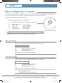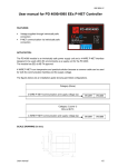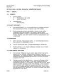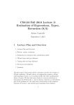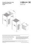
1
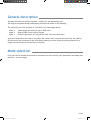
AX1_manual_rev_11_UK.indd 1
09-09-2008 13:37:22
Congratulations choosing tectural values. Thank you!
. You have selected a truly unique design with respect for archi-
It has been an emotional adventure to transform complex functionality into a distinct shape. It is
not hard to work with creative freedom - the real challenge is the art of limitation. Less is more.
We have filled the
with lots of advanced technology that you’ll probably never notice.
Technology that simplifies your life. It is my hope that you will enjoy the ease of use.
This manual contains useful information - please read the section that concerns your application
to ensure optimal performance with your new
access point. I also recommend that you
visit the web site www.key7.dk. The web site provides you with the latest up to date information
about new products including software.
Enjoy your
Nicolaj Haarup
DESIGN by Nicolaj Haarup
AX1_manual_rev_11_UK.indd 2
© Copyright 2008
09-09-2008 13:37:24
User Manual
AX1 & AX2
Rev. 1.1
KEY7 A/S - Denmark
AX1_manual_rev_11_UK.indd 3
09-09-2008 13:37:24
Contents
GENERAL DESCRIPTION................................................................................ 6
MODE SELECTION....................................................................................... 6
MODE OVERVIEW....................................................................................... 7
MOUNTING ........................................................................................ 8
MODE 1 - Stand-alone operation..................................................................... 9
STAND-ALONE............................................................................. 10
MODE 1 SPECIFICATIONS................................................................. 11
MODE 1 WIRING........................................................................... 11
EXAMPLE CONNECTION.................................................................. 12
EXTENDED FUNCTIONALITY............................................................. 12
BASIC CONFIGURATION IN MODE 1..................................................... 13
Master code change............................................................... 13
Service code change.............................................................. 13
User code length................................................................... 14
Door output time.................................................................. 14
Reset to factory default.......................................................... 14
ADVANCED CONFIGURATION IN MODE 1............................................... 15
Alarm output function............................................................ 16
Duress Alarm setup................................................................ 16
Lockout time....................................................................... 17
Buzzer function.................................................................... 17
By-pass output time............................................................... 17
Output polarity.................................................................... 18
Access profile...................................................................... 18
Pulse definition.................................................................... 18
DAILY USE IN MODE 1.................................................................... 19
Create / Modify User codes...................................................... 19
Deleting User codes............................................................... 19
Deleting ALL user codes.......................................................... 19
MODE 2 - KeyLink PRO Access control............................................................. 21
KeyLink PRO Access control............................................................ 22
MODE 2 SELECTION....................................................................... 23
MODE 2 SPECIFICATIONS................................................................. 24
MODE 2 WIRING........................................................................... 24
BUILDING A KEYLINK PRO NETWORK................................................... 25
EXAMPLE CONNECTION.................................................................. 26
CONFIGURATION.......................................................................... 26
Other configuration . ............................................................. 27
AX1_manual_rev_11_UK.indd 4
09-09-2008 13:37:24
MODE 3 - PROTOCOL OPERATION................................................................... 29
PROTOCOL OPERATION.................................................................. 30
PROTOCOL SELECTION................................................................... 31
Protocol overview................................................................. 31
Reset to factory default.......................................................... 32
MODE 3 SPECIFICATIONS................................................................. 32
MODE 3 PROTOCOLS..................................................................... 33
Protocol Wiegand 26.............................................................. 33
Protocol Wiegand MI.............................................................. 34
Protocol Wiegand HID/ATS (26/8 bits)......................................... 35
Protocol Wiegand HID/ATS (32/4 bits)......................................... 36
Protocol Wiegand TAC............................................................. 37
Protocol ABA........................................................................ 38
Protocol ABA UT.................................................................... 39
Protocol ABA TAC................................................................... 40
Protocol AT.......................................................................... 41
Protocol COOPER.................................................................. 42
Protocol CASTLE................................................................... 43
Protocol RS232..................................................................... 44
Protocol OEM1...................................................................... 45
aero MODELS ....................................................................................... 47
CONFORMITY ....................................................................................... 47
AX1_manual_rev_11_UK.indd 5
09-09-2008 13:37:24
General description
The aero AX-series are unique keypads / readers for the demanding user.
The high-end timeless design emphasizes architectural values in any building .
The AX-series can work in either of 3 modes to suit most applications:
Mode 1:
Mode 2:
Mode 3:
Stand-alone operation for up to 1000 users
KeyLink PRO access control system
Protocol operation for integration with 3rd party controllers
aero AX is mounted on the wall or any other flat surface with 4 screws and a hole for the cabling.
All electronics are contained in the slim design making the aero AX-series looking almost like a
magic icon hovering over the surface of the wall.
Mode selection
First you need to decide what mode of operation you will need for your application and make your
selection - see next page:
Page AX1_manual_rev_11_UK.indd 6
09-09-2008 13:37:24
Mode overview
Basically there are 3 different modes of operation. Make your choice based on the 3 boxes below
and proceed directly to the relevant page:
MODE 1:
(default)
MODE 2:
MODE 3:
S TA N D - A L O N E
KeyLink PRO
Access control
Protocol
operation
C h o o s e t his
m o d e f o r simple
1 - d o o r a ccess
o p e r a t i o n.
Re q u i r e s no PC.
Choose this
mode for full
f eatured KEY7
access control
s ystem with
s everal doors
and areas.
Choose this
mode if the A X
is to be int e r faced to a t h i r d
party contr o l
panel.
G o t o PA G E 7
G o t o PA G E 2 1
G o t o PA G E 2 7
For instructions in how to change back to default mode (Mode 1) - please refer to section Reset to
factory default on page 12 and page 30.
Page AX1_manual_rev_11_UK.indd 7
09-09-2008 13:37:24
Mounting
The aero AX must be mounted on a flat surface.
1. The base is mounted on the wall using the supplied 4 screws.
2. A 8mm hole for the cable is drilled.
3. The AX is then fitted into the base and secured with the 2 set screws.
Figure 0: Assembly
Page AX1_manual_rev_11_UK.indd 8
09-09-2008 13:37:26
MODE 1
SECTION
MODE 1 - Stand-alone operation
K E Y 7 A / S • B a v n ehøjvej 19 • DK-8600 Silkeborg • Denmark
Ph o n e + 4 5 8 6 8 6 7 3 0 7 • Fax +45 8686 7177 • [email protected] • www.key7.dk
AX1_manual_rev_11_UK.indd 9
Page 09-09-2008 13:37:26
MODE 1
Stand-alone
Stand-alone mode is the default mode of operation for the aero AX-series.
This mode is used for simple 1-door access operation and requires no PC for setup or daily use.
For instructions in how to change back to Mode 1 from another mode - please refer to section Reset to factory default on page 12 and page 30.
Figure1: Block diagram of components involved in stand-alone mode (Mode 1).
In stand-alone mode the user codes and configurations are done via the keypad of the aero AX.
Creating, modifying and deleting user codes requires the use of the Master code. See p. 16
Modifying the configuration setup requires the use of the Service code. See page 11
K E Y 7 A / S • B a v n ehøjvej 19 • DK-8600 Silkeborg • Denmark
Ph o n e + 4 5 8 6 8 6 7 3 0 7 • Fax +45 8686 7177 • [email protected] • www.key7.dk
AX1_manual_rev_11_UK.indd 10
Page 10
09-09-2008 13:37:26
MODE 1
Specifications
Mode 1 specifications:
Function
Po w e r s u p p l y
Po w e r c o n s u m p t i o n
Dimensions
Weight
Cable
Pr o x r e a d e r
Users
Door output
Door time
Alarm bypass
Bypass time
Duress alarm
Ta m p e r
Ta m p e r l o o p
Operating temperature
Va l u e s , t y p i c a l
8-28V DC
@ 1 2 V: 1 0 0 m A , @ 2 4 V: 5 0 m A
100x140x12mm
400g
white 14-lead, 3m
HID and EM410x (AX1-11 and AX2-11)
M I FA R E ( A X 1 - 2 1 a n d A X 2 - 2 1 )
1000
o p e n c o l l e c t o r, < 1 A / 2 4 V D C
1-998 seconds or on/off
o p t i c a l r e l a y, 1 0 0 m A / 2 4 V
1-998 seconds or on/off
3 seconds, <1A/24VDC
optical wall sensor
o p t i c a l r e l a y, 1 0 0 m A / 2 4 V
-20°C to +65°C
Mode 1 wiring:
Wire
RED
BLACK
YELLOW
GREEN/WHITE
GREEN/BROWN
BLUE
BLUE/RED
VIOLET
PINK
WHITE
BROWN
GREEN
G R AY
G R AY / P I N K
Description
+ Po w e r s u p p l y
- Po w e r s u p p l y
Door output, ground, <1A/24V
By-pass output wire 1, 100mA/50V
By-pass output wire 2, 100mA/50V
Ta m p e r o u t p u t w i r e 1 , 1 0 0 m A / 5 0 V
Ta m p e r o u t p u t w i r e 1 , 1 0 0 m A / 5 0 V
Duress alarm output, ground, <1A/24V
E X I T- b u t t o n
Status input
Sync / Door feed-back
-
K E Y 7 A / S • B a v n ehøjvej 19 • DK-8600 Silkeborg • Denmark
Ph o n e + 4 5 8 6 8 6 7 3 0 7 • Fax +45 8686 7177 • [email protected] • www.key7.dk
AX1_manual_rev_11_UK.indd 11
Page 11
09-09-2008 13:37:26
MODE 1
Example connection
In basic stand-alone mode (Mode 1) the cabling is limited to only 3 wires - or 4 if an optional EXITbutton is required. Figure 2 shows the diagram.
Figure 2: Wiring diagram for a simple single-door application (Mode 1).
Extended functionality
Status input
The white wire controls the mode of access validation when using aero AX1 devices with both
keypad and prox readers. By default the user has to present either a valid pin-code or a valid prox
tag to gain access. By changing the access mode the status input (white wire) is used to control
whether the user has to present both a pin-code and a prox tag or only one of them.
See Access profile on page 15 in section “Advanced Configuration in Mode 1” to learn how to access this mode.
K E Y 7 A / S • B a v n ehøjvej 19 • DK-8600 Silkeborg • Denmark
Ph o n e + 4 5 8 6 8 6 7 3 0 7 • Fax +45 8686 7177 • [email protected] • www.key7.dk
AX1_manual_rev_11_UK.indd 12
Page 12
09-09-2008 13:37:27
MODE 1
Basic Configuration in Mode 1
This chapter describes the basic configuration of the aero AX. Configuration is only required when operating the device as a stand-alone access point (Mode 1). Basic AX configuration is divided into 5 functions.
Configuration is done by entering below sequence:
K S K yy z K
Typical programming sequence:
K
KEY7 logo button (Approx 1½ cm above and right of logo)
S
M
yy
z
Button in light circle
Service code Master code function code
configuration data
ο
(Default 09876543)
(Default 12345678)
(Always 2 digits)
(1 to 16 digits)
Position of hidden K-button
Note: Technician code is only valid 60 minutes after applying power.
In the following sections the 5 function configurations are explained …
Master code change [10]
The Master code is used to create and modify user codes. It is important to change the default
Master code to prevent unauthorized modification the user codes.
K M K 10 [nm1] [nm2] K ο
M
nm1
nm2
Master code (default 12345678)
The new Master code
Repeated new Master code
NOTE: Master code must always contain 8 digits.
Service code change [30]
The Service code is used to edit function parameters. It is important to change the default
service code to prevent unauthorized modification the functionality.
K S K 30 [ns1] [ns2] K ο
S
ns1
ns2
Service code (default 09876543)
The new Service code
Repeated new Service code
NOTE: Service code must always contain 8 digits.
NOTE: The Service code will time out after 60 minutes. Re-enabling can be done either way:
* Enter the Master code + K
* Disconnect power and re-connect power
K E Y 7 A / S • B a v n ehøjvej 19 • DK-8600 Silkeborg • Denmark
Ph o n e + 4 5 8 6 8 6 7 3 0 7 • Fax +45 8686 7177 • [email protected] • www.key7.dk
AX1_manual_rev_11_UK.indd 13
Page 13
09-09-2008 13:37:29
MODE 1
User code length [31]
This function specifies the length of the user codes. The length can be from 2 - 8 digits. Default length is 4 digits.
K S K 31 [z] K ο
S
z
Service code (default 09876543)
2-8
NOTE: Changing the code length with this function should be done before creating the user code to avoid truncating or deleting the created codes.
Door output time [33]
This functions specifies the active time in seconds for the Door output. This output is activated
when a user code is entered / prox is presented.
The output can be configured as a toggle output entering ‘0’ as the z-value.
K S K 33 [z] K ο
S
z
NOTE:
NOTE:
NOTE:
Service code (default 09876543)
0-999 (Default value: 3)
Door output is the yellow wire. See page 9
When active this output “makes a ground”.
When using the output as a toggle-output the output changes every time the a valid user code is entered. The output is only is only active as long as the status input (WHITE wire) is low (grounded).
Reset to factory default
Using this function resets the AX1 back to factory default settings.
1:
2:
3:
4:
5:
Disconnect power supply
Connect PINK wire to BLACK wire
Re-connect power
Wait for 5 seconds and notice circle turns red
Release PINK wire from BLACK wire within 5 seconds without disconnecting the power supply
AX1 is now reset to factory settings and all codes are cleared.
NOTE: All user codes are deleted.
K E Y 7 A / S • B a v n ehøjvej 19 • DK-8600 Silkeborg • Denmark
Ph o n e + 4 5 8 6 8 6 7 3 0 7 • Fax +45 8686 7177 • [email protected] • www.key7.dk
AX1_manual_rev_11_UK.indd 14
Page 14
09-09-2008 13:37:29
MODE 1
Advanced Configuration in Mode 1
This section is only required if advanced functions are needed - otherwise refer to section
“Basic Configuration in Mode 1” - see page 13.
The aero AX has many very powerful functions that enable it to be used in almost any application. A complete description is far to comprehensive to be printed in this user manual. Only some are covered here and others can be
found on www.key7.dk
Advanced function cue:
3-door mode
Used when needed to control up to 3 door from one AX1. Please refer to www.key7.dk
Door feed-back
Used when need for alarm when door is left open or forced open. Please refer to www.key7.dk
Sluice operation
Used when two AX1 control two doors in a sluice. Please refer to www.key7.dk
Configuration generator
A web-based tool. This is a really useful tool when configuring the aero functions. Simply make your selections and
enter one single sequence. You’ll find it on www.key7.dk
On/off operation
If the outputs have to be operated in an on/off toggle mode some things have to considered.
Reed more on www.key7.dk
Alarm functions
The AX1 offers a variety of alarm functions including Sabotage, Duress and Tampering.
See “Alarm output function” on page 16.
Duress alarm
During duress a secret code is entered to trigger a silent alarm. See “Duress Alarm saetup” on page 16.
Lock-out
Code tampering can be prevented . Read how in section “Lockout time” on page 17.
Buzzer
If the behavior of the buzzer need to be altered the please refer to “Buzzer function” on page 17.
By-pass operation
The AX1 has a special output specially designed to by-pass zones. See “By-pass output time” on page 17 and for
advanced by-pass use please refer to www.key7.dk
Access profile
It is possible to have different security levels depending on an external signal. See “Access profiles” on page 18 and
read more on www.key7.dk
K E Y 7 A / S • B a v n ehøjvej 19 • DK-8600 Silkeborg • Denmark
Ph o n e + 4 5 8 6 8 6 7 3 0 7 • Fax +45 8686 7177 • [email protected] • www.key7.dk
AX1_manual_rev_11_UK.indd 15
Page 15
09-09-2008 13:37:29
MODE 1
Alarm output function [43]
The aero AX contains several alarm functions:
Trigger
Sabotage
Code tamper
Duress
Trigger reason
Output (see p. 9)
An optical sensor in AX sees the absence of wallTamper
3 consecutive false user codes
Tamper
A secret code (see Duress Alarm Setup below)
Duress (3 seconds)
Sabotage is always enabled!
The other triggers can be controlled using below procedure:
K S K 43 [z] K ο
S
z
Service code (default 09876543)
0 - 3 (default 0)
Alarm trigger, z:
0: Only Sabotage (can not be disabled)
1: Enable Duress open alarm trigger
2: Enable Code tampering trigger (requires that Code Tamper Lockout time on page 14 is con
figured for > 0 seconds (default 30 seconds))
3: Enable Duress open alarm and Code tampering trigger
Duress Alarm setup [44]
When using this option the AX can trigger a silent alarm when a “secret” code is entered. This
is especially useful during duress. The victim enters his/her normal user code but with last
digit as specified in this function. Everything works normally but in addition a silent alarm is
triggered.
For this function to be activeated it must be enabled - se “Alarm output function”.
K S K 44 [z] K ο
S
z
Service code (default 09876543)
0-9
NOTE: If using this function none of the user codes may contain the z-digit in the last position!
K E Y 7 A / S • B a v n ehøjvej 19 • DK-8600 Silkeborg • Denmark
Ph o n e + 4 5 8 6 8 6 7 3 0 7 • Fax +45 8686 7177 • [email protected] • www.key7.dk
AX1_manual_rev_11_UK.indd 16
Page 16
09-09-2008 13:37:29
MODE 1
Lockout time [38]
This functions specifies the lockout time in seconds after 3 invalid entries. Using this function
prevents code tampering.
K S K 38 [z] K ο
S
z
Service code (default 09876543)
0-999 (default is 30 seconds)
NOTE: If z=0 the lockout is disabled.
Buzzer function [36]
This functions specifies the behavior of the buzzer.
K S K 36 [z] K ο
S
z
Service code (default 09876543)
Buzzer function 0-4 (default 1)
Buzzer function:
0: Buzzer off
1: Buzzer on during access period (door output time period)
2: Buzzer on for ½ second during access period (door output time period)
By-pass output time [35]
This functions specifies the active time in seconds for the By-pass output. This output is activated when a user code is entered / prox is presented.
K S K 35 [z] K ο
S
z
Service code (default 09876543)
0-999 (Default value: 30)
NOTE: By-pass output is an isolated output on the green/white and green/brown wires. See page 9.
NOTE: When active there will be approximately 5 ohms resistance between these wires.
K E Y 7 A / S • B a v n ehøjvej 19 • DK-8600 Silkeborg • Denmark
Ph o n e + 4 5 8 6 8 6 7 3 0 7 • Fax +45 8686 7177 • [email protected] • www.key7.dk
AX1_manual_rev_11_UK.indd 17
Page 17
09-09-2008 13:37:29
MODE 1
Output polarity [34]
This functions specifies the output “polarity” of the by-pass and the door output.
The by-pass output can be either open circuit or closed circuit (default).
The door output can be either high (default) or low.
K S K 34 [z] K ο
S
z
Service code (default 09876543)
Output polarity 0,1,4,5 (default 0)
Output polarity:
0: by-pass normal
1: by-pass normal
4: by-pass normal
5: by-pass normal
NOTE:
NOTE:
open circuit, door high. (default)
closed circuit, door high
open circuit, door low
closed circuit, door low
If by-pass is closed circuit the resistance between the output wires will be
approximately 5 ohms.
Door output can sink up to 1A during low. That means the lock must be connected to + (RED wire) and door output (YELLOW wire).
Access Profile [32]
Access profile specifies whether the user has to present both the pin code and the prox tag or
if it is sufficient to use either the pin code or the prox tag.
K S K 32 0 [ab] K ο
S
a
b
Service code (default 09876543)
0 or 1. Access profile when “Status Input” wire is not connected
0 or 1. Access profile when “Status Input” wire is connected to ground.
Access profile (a and b):
0: Pin code and Prox
1: Pin code or Prox
Default value for a: 1
Default value for b: 1
NOTE: Status Input is the WHITE wire. See page 9.
Pulse definition [37]
This functions specifies the pulse length used in the “Buzzer function”. The time in 1/10th of
seconds is sepcified by the z-value.
K S K 37 [z] K ο
S
z
Service code (default 09876543)
0 - 999 (default 5)
K E Y 7 A / S • B a v n ehøjvej 19 • DK-8600 Silkeborg • Denmark
Ph o n e + 4 5 8 6 8 6 7 3 0 7 • Fax +45 8686 7177 • [email protected] • www.key7.dk
AX1_manual_rev_11_UK.indd 18
Page 18
09-09-2008 13:37:29
MODE 1
Daily use in Mode 1
Daily use is very straight forward:
Enter user code (and/or present prox tag) and the light circle (ο) changes from red to green
indicating access. When access ends the light circle fades back from green to red.
Create / Modify User codes
This procedure creates / modifies user codes. Up to 1000 user codes and/or prox tags can be
stored:
K M [aaa] [u] [p] ο
M
aaa
u
p
Master code (default 12345678)
000-999, Memory location for user code (a total of 1000 locations are available)
User code. Number of digits as defined in function Code Length (default 4).
Prox tag. Hold tag to reader (in red circle)
NOTE: After touching ο the circle keeps flashing - this indicates that a new user can be created / modified by continuing entering a new memory location [aaa].
When finished then abort procedure by touching ο once more.
Deleting User codes
This procedure deletes user codes.
K M [aaa] ο
M
aaa
Master code (default 12345678)
000-999, Memory location for user code (a total of 1000 locations are available)
NOTE: After touching ο the circle keeps flashing - this indicates that a new user can be deleted by continuing entering a new memory location [aaa].
When finished then abort procedure by touching ο once more.
Deleting ALL User codes
This procedure deletes all user codes.
K M K 120000 K
M
Master code (default 12345678)
NOTE: This procedure can NOT BE UN-DONE!
K E Y 7 A / S • B a v n ehøjvej 19 • DK-8600 Silkeborg • Denmark
Ph o n e + 4 5 8 6 8 6 7 3 0 7 • Fax +45 8686 7177 • [email protected] • www.key7.dk
AX1_manual_rev_11_UK.indd 19
Page 19
09-09-2008 13:37:30
MODE 1
--- END OF MODE 1 ---
K E Y 7 A / S • B a v n ehøjvej 19 • DK-8600 Silkeborg • Denmark
Ph o n e + 4 5 8 6 8 6 7 3 0 7 • Fax +45 8686 7177 • [email protected] • www.key7.dk
AX1_manual_rev_11_UK.indd 20
Page 20
09-09-2008 13:37:31
MODE 2
SECTION
M O D E 2 - K eyLink PRO Access control
K E Y 7 A / S • B a v n ehøjvej 19 • DK-8600 Silkeborg • Denmark
Ph o n e + 4 5 8 6 8 6 7 3 0 7 • Fax +45 8686 7177 • [email protected] • www.key7.dk
AX1_manual_rev_11_UK.indd 21
Page 21
09-09-2008 13:37:31
MODE 2
KeyLink PRO Access control
In KeyLink PRO access control mode (Mode 2) the aero AX-series will be part of an access control
system with an unlimited number of access points. Such a system is not based on a traditional
controller but uses distributed intelligence and a KeyLink PRO software running on a server. In this
mode only the addressing of the access point is required. No other configuration is required.
Figure 3: Basic structure of a KeyLink PRO access control setup (Mode 2).
As shown on figure 3 there is no central controller - only the access points and one or more interfaces. The KeyLink PRO software is executed on a Windows PC and handles only the graphical user
interface, updates and logging. The access control is handled individually by the access points.
Key features:
• Up to 31 access points can be connected per 1 interface.
• An unlimited number of interfaces can be controlled from the KeyLink PRO software.
• KeyLink PRO is a server/client application allowing multiple clients. In small installations the server and client can be run from the same PC.
• Up to 1000 simultaneous users per access point.
• KeyLink PRO offers easy administration of users, sites, periods, logs and reports.
From a hardware point of view the functions of the AX is the same as in Mode 1 - e.g. the door
lock is directly controlled from the AX1 and EXIT-buttons can be connected. Configuration is done
using the KeyLink PRO software.
MODE SELECTION: See next page
K E Y 7 A / S • B a v n ehøjvej 19 • DK-8600 Silkeborg • Denmark
Ph o n e + 4 5 8 6 8 6 7 3 0 7 • Fax +45 8686 7177 • [email protected] • www.key7.dk
AX1_manual_rev_11_UK.indd 22
Page 22
09-09-2008 13:37:31
MODE 2
Mode 2 selection
Selecting Mode 2 is handled automatically since the AX detects the presence of a KeyLink PRO
network and switches automatically from Mode 1 (stand-alone mode) to Mode 2. The absence of
the KeyLink PRO network for more than two hours brings the AX1 back to Mode 1. See the following pages on how build a KeyLink PRO network.
K E Y 7 A / S • B a v n ehøjvej 19 • DK-8600 Silkeborg • Denmark
Ph o n e + 4 5 8 6 8 6 7 3 0 7 • Fax +45 8686 7177 • [email protected] • www.key7.dk
AX1_manual_rev_11_UK.indd 23
Page 23
09-09-2008 13:37:31
MODE 2
Specifications
Mode 2 specifications:
Function
Po w e r s u p p l y
Po w e r c o n s u m p t i o n
Dimensions
Weight
Cable
Pr o x r e a d e r
Users
Door output
Door time
Alarm bypass
Bypass time
Duress alarm
Ta m p e r
Ta m p e r l o o p
Operating temperature
Va l u e s , t y p i c a l
8-28V DC
@ 1 2 V: 1 0 0 m A , @ 2 4 V: 5 0 m A
100x140x12mm
400g
white 14-lead, 3m
HID and EM410x (AX1-11 and AX2-11)
M I FA R E ( A X 1 - 2 1 a n d A X 2 - 2 1 )
1000
o p e n c o l l e c t o r, < 1 A / 2 4 D C
1-998 seconds or on/off
o p t i c a l r e l a y, 1 0 0 m A / 2 4 V
1-998 seconds or on/off
3 seconds, <1A/24VDC
optical wall sensor
o p t i c a l r e l a y, 1 0 0 m A / 2 4 V
-20°C to +65°C
Mode 2 wiring:
Wire
RED
BLACK
YELLOW
GREEN/WHITE
GREEN/BROWN
BLUE
BLUE/RED
VIOLET
PINK
WHITE
BROWN
GREEN
G R AY / P I N K
G R AY
Description
P o w e r s u p p l y, 8 - 2 4 V D C
P o w e r s u p p l y, 0 V
Door output, ground, <1A/24V
By-pass output wire 1, 100mA/50V
By-pass output wire 2, 100mA/50V
Ta m p e r o u t p u t w i r e 1 , 1 0 0 m A / 5 0 V
Ta m p e r o u t p u t w i r e 1 , 1 0 0 m A / 5 0 V
Duress alarm output, ground, <1A/24V
E X I T- b u t t o n
Status input
Data A
Data B
K E Y 7 A / S • B a v n ehøjvej 19 • DK-8600 Silkeborg • Denmark
Ph o n e + 4 5 8 6 8 6 7 3 0 7 • Fax +45 8686 7177 • [email protected] • www.key7.dk
AX1_manual_rev_11_UK.indd 24
Page 24
09-09-2008 13:37:32
MODE 2
Building a KeyLink PRO network
A KeyLink PRO network is based on the electric RS485 bus. We recommend a CAT5 (or higher)
twisted wires cable must be used and that a total bus length of 1000 meters can be obtained. The
interface between this network and the PC is a SA120-U (USB) or a SA120-UL (LAN).
Figure 4: The KeyLink PRO access control network
Any number of SA120’s can be connected to the PC. SA120-U and SA120-UL can be mixed in an
installation but only 1 on each RS485-segment.
Note that a good RS485 bus is terminated with 100 ohms in each end of the cable.
K E Y 7 A / S • B a v n ehøjvej 19 • DK-8600 Silkeborg • Denmark
Ph o n e + 4 5 8 6 8 6 7 3 0 7 • Fax +45 8686 7177 • [email protected] • www.key7.dk
AX1_manual_rev_11_UK.indd 25
Page 25
09-09-2008 13:37:34
MODE 2
Example connection
The wiring is much like when in Mode 1 (stand-alone) but with the addition of the bus connection
(Data A and Data B). The EXIT button is optional. Figure 5 shows the diagram.
Figure 5: Typical access point wiring in a KeyLink PRO network
Configuration
The only configuration needed is the address setting:
1)
2)
3)
4)
Connect power and network (Data A and B)
Circle flashes red indicating the need of a valid address
Enter a 2-digit address in the range from 01 to 31
Circle shifts from flashing to constant red light indicating that it now has a valid address
Background: When connecting the aero AX to the KeyLink PRO network it will recognize the communication and knows that it has to work in Mode 2. The AX does also know that it has an invalid
address and without a valid address it can not communicate with the KeyLink PRO server and it
starts thus flashing red with its circle. This should alert the installer to enter an address in the
range from 01 to 31.
K E Y 7 A / S • B a v n ehøjvej 19 • DK-8600 Silkeborg • Denmark
Ph o n e + 4 5 8 6 8 6 7 3 0 7 • Fax +45 8686 7177 • [email protected] • www.key7.dk
AX1_manual_rev_11_UK.indd 26
Page 26
09-09-2008 13:37:36
MODE 2
If, for some reason, the address has to be changed after it has been set enter below sequence:
K 09876543 K 39 [aa] K
K
aa
KEY7 logo button (Approx 1½ cm above and right of logo)
Address, range fro 01 to 31, (2 digits)
Position of hidden K-button
Note that this command must be performed within 1 hour after applying power. If 1 hour has been
exceeded disconnect and reconnect power or enter this sequence:
KMο
M
Master code (default 12345678)
Other configuration
Besides the setting of a valid address the configuration and programming of user codes are all
done in the KeyLink PRO software. Please refer to the KeyLink PRO software manual.
K E Y 7 A / S • B a v n ehøjvej 19 • DK-8600 Silkeborg • Denmark
Ph o n e + 4 5 8 6 8 6 7 3 0 7 • Fax +45 8686 7177 • [email protected] • www.key7.dk
AX1_manual_rev_11_UK.indd 27
Page 27
09-09-2008 13:37:37
MODE 2
--- END OF MODE 2 ---
K E Y 7 A / S • B a v n ehøjvej 19 • DK-8600 Silkeborg • Denmark
Ph o n e + 4 5 8 6 8 6 7 3 0 7 • Fax +45 8686 7177 • [email protected] • www.key7.dk
AX1_manual_rev_11_UK.indd 28
Page 28
09-09-2008 13:37:37
MODE 3
SECTION
MODE 3 - Protocol Operation
K E Y 7 A / S • B a v n ehøjvej 19 • DK-8600 Silkeborg • Denmark
Ph o n e + 4 5 8 6 8 6 7 3 0 7 • Fax +45 8686 7177 • [email protected] • www.key7.dk
AX1_manual_rev_11_UK.indd 29
Page 29
09-09-2008 13:37:38
MODE 3
Protocol operation
Choose this mode if the AX is to be interfaced to a third party control panel. In protocol operation
the AX has no user code memory. AX sends keypress and prox tag information to a control panel
via the selected interface. If supported by the selected interface the control panel can send commands to the AX1 instructing it to activate its outputs.
Figure 6: Basic interface types in Protocol Operation (Mode 3).
In addition to standard Wiegand, ABA and RS232 protocols the aero AX also includes dedicated
protocols for integration with many third party control panels - e.g.
* ATS
* Castle Care Tech
* Cooper Security
* Alphatronics
* Scantronics
* TAC
* ESMI
* UNITEK
M O D E / P R O TO C O L S E L E C T I O N : S e e n e x t p a g e
K E Y 7 A / S • B a v n ehøjvej 19 • DK-8600 Silkeborg • Denmark
Ph o n e + 4 5 8 6 8 6 7 3 0 7 • Fax +45 8686 7177 • [email protected] • www.key7.dk
AX1_manual_rev_11_UK.indd 30
Page 30
09-09-2008 13:37:39
MODE 3
Protocol selection
The aero AX1 contains protocols for operation with most third party control panels.
Make sure the AX is in Mode 1 (factory default). If not in Mode 1 refer to section Reset to factory default on the
next page.
Typical programming sequence: K
S
p
a
t
KEY7 logo Service code protocol id
address
tamper function
K [S] K 40 [p] [a] [t] K
(Approx 1½cm above and right of logo)
(Default 09876543)
(2 digits)
(1-2 digits)
(1digit)
Note: Service code is only valid 60 minutes after applying power.
‘a’ and ‘t’ are only required on some protocols.
Position of hidden K-button
Although protocol selection is very straight forward there is one rule to remeber:
PROTOCOL SELECTION IS ONLY POSSIBLE WHEN IN MODE1 (STAND-ALONE MODE)
Protocol overview
Protocol
Description
Selection procedure
ABA
Normal ABA magnetic card rd
WIEGAND 26
26-bit Wiegand
RS232
Serial log mode
WIEGAND MI
Mototola/Indala Wiegand
ABA UT
ABA for Unitek
AT
Alphatronics RS485 protocol
WIEGAND 26 HID
2 6 / 8 - b i t W i e g a n d H I D / AT S
COOPER
Cooper Security RS485 protocol
WIEGAND TAC
TA C W i e g a n d I / N e t S e v e n
CASTLE
C a s t l e C a r e Te c h R S 4 8 5 p r o t o c o l
ABA TAC
A B A f o r TA C I / N e t S e v e n
WIEGAND 32 HID
3 2 / 4 - b i t W i e g a n d H I D / AT S
KSK
KSK
KSK
KSK
KSK
KSK
KSK
KSK
KSK
KSK
KSK
KSK
K
40 02 K
40 03 K
40 04 K
40 05 K
40 01
40 06 a t
40 07
K
40 08 a
40 09
K
K
K
40 10 a
K
K
40 13 K
40 11
NOTE:
S is the Service code
a is the desired address
t=1: tamper enabled
t=0: tamper disabled
K E Y 7 A / S • B a v n ehøjvej 19 • DK-8600 Silkeborg • Denmark
Ph o n e + 4 5 8 6 8 6 7 3 0 7 • Fax +45 8686 7177 • [email protected] • www.key7.dk
AX1_manual_rev_11_UK.indd 31
Page 31
09-09-2008 13:37:40
MODE 3
Reset to factory default
If the AX is NOT IN MODE 1 (e.g. a protocol has already been selected) the device has to be reset back to factory default setting with the following procedure prior to protocol selection:
Using this function resets the AX back to factory default settings.
1:
2:
3:
4:
5:
Disconnect power supply
Connect PINK wire to BLACK wire
Re-connect power
Wait for 5 seconds and notice circle turns red
Release PINK wire from BLACK wire within 5 seconds without disconnecting the power supply
AX1 is now reset to factory settings and in MODE 1.
Specifications
Mode 3 specifications:
Function
Po w e r s u p p l y
Po w e r c o n s u m p t i o n
Dimensions
Weight
Cable
Pr o x r e a d e r
Pr o t o c o l s
Door output
Ta m p e r
Ta m p e r l o o p
Operating temperature
Operating humidity
Va l u e s , t y p i c a l
8-28V DC
@ 1 2 V: 1 0 0 m A , @ 2 4 V: 5 0 m A
100x140x12mm
400g
white 14-lead, 3m
HID and EM410x (AX1-11 and AX2-11)
M I FA R E ( A X 1 - 2 1 a n d A X 2 - 2 1 )
11
o p e n c o l l e c t o r, < 1 A / 2 4 V D C
optical wall sensor
o p t i c a l r e l a y, 1 0 0 m A / 2 4 V
-20°C to +65°C
0-95% non condensing
K E Y 7 A / S • B a v n ehøjvej 19 • DK-8600 Silkeborg • Denmark
Ph o n e + 4 5 8 6 8 6 7 3 0 7 • Fax +45 8686 7177 • [email protected] • www.key7.dk
AX1_manual_rev_11_UK.indd 32
Page 32
09-09-2008 13:37:41
MODE 3
Mode 3 protocols
This section describes the protocols and their selection.
Protocol Wiegand 26
When in Mode 1 enter this sequence to enable Protocol Wiegand 26:
K [Service code] K 40 02 K
aero AX1 is now ready to be used as a 26-bit Wiegand reader.
Inputs/Outputs:
WIRE
FUNCTION
I/O TYPE
YELLOW
Data 0
output (open collector)
GREEN
Data 1
output (open collector)
WHITE
High:
ο
input
PINK
High: Buzzer off / Low: Buzzer on
input
ο
/ Low:
Operation:
Keypress are converted and transmitted immediately. Keypress are transmitted as 10-bit Wiegand (parity(1), key(8) parity(1) ). The data format is as follows:
KEY-data: 0: 1: 2: 3: 4: 5: 6: 7: 8: 9: K: ο: F0 Hex
E1 Hex
D2 Hex
C3 Hex
B4 Hex
A5 Hex
96 Hex
87 Hex
78 Hex
69 Hex
5A Hex
4B Hex
Prox data are transmitted as 26-bit Wiegand (parity(1), facility(8), data(16) parity(1) ).
Facility code is default ‘7’.
K E Y 7 A / S • B a v n ehøjvej 19 • DK-8600 Silkeborg • Denmark
Ph o n e + 4 5 8 6 8 6 7 3 0 7 • Fax +45 8686 7177 • [email protected] • www.key7.dk
AX1_manual_rev_11_UK.indd 33
Page 33
09-09-2008 13:37:41
MODE 3
Protocol Wiegand MI
When in Mode 1 enter this sequence to enable Protocol Motorola / Indala Wiegand:
K [Service code] K 40 04 K
aero AX1 is now ready to be used as a Motorola / Indala output-compatible Wiegand reader.
Inputs/Outputs:
WIRE
FUNCTION
I/O TYPE
YELLOW
Data 0
output (open collector)
GREEN
Data 1
output (open collector)
WHITE
High:
ο
input
PINK
High: Buzzer off / Low: Buzzer on
input
ο
/ Low:
Operation:
Keypress are converted and transmitted immediately. Keypress are transmitted as 8-bit Wiegand ( key(8) ). The data format is as follows:
KEY-data: 0: 1: 2: 3: 4: 5: 6: 7: 8: 9: K: ο: F0 Hex
E1 Hex
D2 Hex
C3 Hex
B4 Hex
A5 Hex
96 Hex
87 Hex
78 Hex
69 Hex
5A Hex
4B Hex
Prox data are transmitted as 26-bit Wiegand (parity(1), facility(8), data(16) parity(1) ).
K E Y 7 A / S • B a v n ehøjvej 19 • DK-8600 Silkeborg • Denmark
Ph o n e + 4 5 8 6 8 6 7 3 0 7 • Fax +45 8686 7177 • [email protected] • www.key7.dk
AX1_manual_rev_11_UK.indd 34
Page 34
09-09-2008 13:37:41
MODE 3
Protocol Wiegand 26/26 HID
Before selecting the HID 26-bit output protocol you should decide if you would like to change
the prox reader from an EM4100-compatible reader to a HID-compatible reader so the AX will
accept HID cards.
K [Service code] K 49 0 K
This will make the AX read EM4100-compatible tags/
cards. This is the default mode.
K [Service code] K 49 1 K
This will make the AX read HID-compatible tags/cards
(125kHz).
When in Mode 1 enter this sequence to enable Protocol 26 HID Wiegand:
K [Service code] K 40 07 K
aero AX is now ready to be used as a HID output-compatible Wiegand reader for the use with
e.g. an ATS central panel. The output is 26-bit card data and 26-bit key data.
Inputs/Outputs:
WIRE
FUNCTION
I/O TYPE
YELLOW
Data 0
output (open collector)
GREEN
Data 1
output (open collector)
WHITE
High:
ο
input
PINK
High: Buzzer off / Low: Buzzer on
input
ο
/ Low:
Operation:
KEY data are transmitted after 4 consecutive entries followed by touching the
4 digitgs are entered only the last 4 digits are transmitted.
ο. If more than
PROX data are transmitted as 26-bit Wiegand ( (parity(1), facility(8), data(16) parity(1) ).
Key data are transmitted as 26-bit Wiegand ( (parity(1), facility(8), data(16) parity(1) ).
K E Y 7 A / S • B a v n ehøjvej 19 • DK-8600 Silkeborg • Denmark
Ph o n e + 4 5 8 6 8 6 7 3 0 7 • Fax +45 8686 7177 • [email protected] • www.key7.dk
AX1_manual_rev_11_UK.indd 35
Page 35
09-09-2008 13:37:41
MODE 3
Protocol Wiegand 32/4 HID
Before selecting the HID 32-bit output protocol you should decide if you would like to change
the prox reader from an EM4100-compatible reader to a HID-compatible reader so the AX will
accept HID cards.
K [Service code] K 49 0 K
This will make the AX read EM4100-compatible tags/
cards. This is the default mode.
K [Service code] K 49 1 K
This will make the AX read HID-compatible tags/cards
(125kHz).
When in Mode 1 enter this sequence to enable Protocol 32/4 HID Wiegand:
K [Service code] K 40 13 K
aero AX1 is now ready to be used as a HID output-compatible Wiegand reader for the use with
e.g. an ATS central panel. The output is 32-bit card data and 4-bit key data.
Inputs/Outputs:
WIRE
FUNCTION
I/O TYPE
YELLOW
Data 0
output (open collector)
GREEN
Data 1
output (open collector)
WHITE
High:
ο
input
PINK
High: Buzzer off / Low: Buzzer on
input
ο
/ Low:
Operation:
KEY data are transmitted after 4 consecutive entries followed by touching the
4 digitgs are entered only the last 4 digits are transmitted.
ο. If more than
PROX data are transmitted as 32-bit Wiegand ( (parity(1), facility(8), data(16) parity(1) ).
Key data are transmitted as 4-bit Wiegand ( data(4) ).
K E Y 7 A / S • B a v n ehøjvej 19 • DK-8600 Silkeborg • Denmark
Ph o n e + 4 5 8 6 8 6 7 3 0 7 • Fax +45 8686 7177 • [email protected] • www.key7.dk
AX1_manual_rev_11_UK.indd 36
Page 36
09-09-2008 13:37:41
MODE 3
Protocol Wiegand TAC
When in Mode 1 enter this sequence to enable Protocol TAC / Inet7 Wiegand:
K [Service code] K 40 09 K
aero AX1 is now ready to be used as a Wiegand reader for the use with a TAC / Inet7 control
panel.
Inputs/Outputs:
WIRE
FUNCTION
I/O TYPE
YELLOW
Data 0
output (open collector)
GREEN
Data 1
output (open collector)
VIOLET
AUX OUTPUT
auxiliary output
WHITE
High:
ο
input
PINK
High: Buzzer off / Low: Buzzer on
input
ο
/ Low:
Operation:
Keypress are converted and transmitted immediately. Keypress are transmitted as 8-bit Wiegand ( key(8) ). ο activates teh AUX output (VIOLET). The data format is as follows:
KEY-data: 0: 1: 2: 3: 4: 5: 6: 7: 8: 9: K: ο: F0 Hex
E1 Hex
D2 Hex
C3 Hex
B4 Hex
A5 Hex
96 Hex
87 Hex
78 Hex
69 Hex
5A Hex
4B Hex
PROX data are transmitted as 40-bit Wiegand ( parity(1), facility(8), dayta(24), parity(1) )
NOTE: Card data are encrypted
Figure 7: Example of connection with Protocol TAC Wiegand
K E Y 7 A / S • B a v n ehøjvej 19 • DK-8600 Silkeborg • Denmark
Ph o n e + 4 5 8 6 8 6 7 3 0 7 • Fax +45 8686 7177 • [email protected] • www.key7.dk
AX1_manual_rev_11_UK.indd 37
Page 37
09-09-2008 13:37:41
MODE 3
Protocol ABA (Magnetic Crad Reader)
When in Mode 1 enter this sequence to enable Protocol ABA:
K [Service code] K 40 01 K
aero AX1 is now ready to be used as a Magnetic Card reader featuring the ABA track II protocol.
Inputs/Outputs:
WIRE
FUNCTION
I/O TYPE
GREEN
Card Clock
output (open collector)
VIOLET
Card Data
output (open collector)
YELLOW
Card Load
output (open collector)
WHITE
High:
ο
input
PINK
High: Buzzer off / Low: Buzzer on
input
ο
/ Low:
Operation:
Keypress are transmitted after pushing the
follows:
ο. Up to 8 digits can be sent. The data format is as
KEY-data: B00000000xxxxxxxxF
Prox tag reading are converted from HEX to BCD and are transmitted immediatly in this format:
PROX-data: BxxxxxxxxxxxxxxxxF
Figure 8: Example (ESMI) of connection with Protocol ABA
K E Y 7 A / S • B a v n ehøjvej 19 • DK-8600 Silkeborg • Denmark
Ph o n e + 4 5 8 6 8 6 7 3 0 7 • Fax +45 8686 7177 • [email protected] • www.key7.dk
AX1_manual_rev_11_UK.indd 38
Page 38
09-09-2008 13:37:42
MODE 3
Protocol ABA UT (Magnetic Crad Reader)
When in Mode 1 enter this sequence to enable Protocol UT ABA:
K [Service code] K 40 05 K
aero AX1 is now ready to be used as a Magnetic Card reader featuring the Unitek ABA track II
protocol. The aero AX1 has same functionality as an original Unitek prox reader.
Inputs/Outputs:
WIRE
FUNCTION
I/O TYPE
GREEN
(Terminal 28) Card Clock
output (open collector)
VIOLET
(Terminal 27) Card Data
output (open collector)
YELLOW
Card Load
output (open collector)
WHITE
(Terminal 24) High:
PINK
(Terminal 25) High: Buzzer for 1 sec.
ο
/ Low:
ο
input
input
Figure 9: Example of connecting a Unitek LS10 using Protocol UT ABA
K E Y 7 A / S • B a v n ehøjvej 19 • DK-8600 Silkeborg • Denmark
Ph o n e + 4 5 8 6 8 6 7 3 0 7 • Fax +45 8686 7177 • [email protected] • www.key7.dk
AX1_manual_rev_11_UK.indd 39
Page 39
09-09-2008 13:37:44
MODE 3
Protocol ABA TAC (Magnetic Crad Reader)
When in Mode 1 enter this sequence to enable Protocol TAC ABA:
K [Service code] K 40 11 K
aero AX1 is now ready to be used as a Magnetic Card reader featuring the TAC ABA track II
protocol.
Inputs/Outputs:
WIRE
FUNCTION
I/O TYPE
GREEN
Card Clock
output (open collector)
VIOLET
Card Data
output (open collector)
YELLOW
Card Data
output (open collector)
WHITE
High:
ο
input
PINK
High: Buzzer off / Low: Buzzer on
input
ο
/ Low:
Operation:
Keypress are converted to TAC-format and are transmitted immediately. Keypress are transmitted as 5-bit ABA
KEY-data: x
Prox tag reading are converted to TAC-format and are transmitted immediatly in this format:
PROX-data: BxxxxxxxxxxxxxxxxF
K E Y 7 A / S • B a v n ehøjvej 19 • DK-8600 Silkeborg • Denmark
Ph o n e + 4 5 8 6 8 6 7 3 0 7 • Fax +45 8686 7177 • [email protected] • www.key7.dk
AX1_manual_rev_11_UK.indd 40
Page 40
09-09-2008 13:37:44
MODE 3
Protocol AT
When in Mode 1 enter this sequence to enable Protocol AT:
K [Service code] K 40 06 a t K
a: address ID -> 1-8 or 1-4 depending of Alphatronics controller model
t: tamper disable/enable -> 0: disable, 1: enable
aero AX1 is now ready to be used as an Alphatronics access point using its RS485-based bus.
Inputs/Outputs:
WIRE
FUNCTION
I/O TYPE
GRAY/PINK
DATA A
RS/485
GRAY
DATA B
RS/485
PINK
MODE
input
GREEN
DOOR LOCK 1
output
YELLOW
DOOR LOCK 2
output
BROWN
SYNC
in/out
MODE (PINK wire)
Low: AX1 will behave like a normal Alphatronics access point.
High (or open connected): AX1 will behave like a normal Alphatronics by-pass switch
DOOR LOCK 1 (GREEN wire)
Ground: Led B signal from Alphatronics control panel is
OFF.
High (high impedance): Led B signal from Alphatronics
control panel is ON.
This output can be used to drive a door lock. Lock
should be connected between ‘+’ and GREEN.
DOOR LOCK 2 (YELLOW wire)
Ground: This indicates by-pass time.
High (high impedance): This indicates normal state (bypass time not activated)
This output can be used to drive a door lock. Lock
should be connected between ‘+’ and YELLOW.
LIGHT RING:
ο (red circle): 230V is present AND Led A is on.
ο (green circle): 230V is present
ο (dark circle): 230V not present
Figure 10: Example of connecting
an Alphatronics control panel using
Protocol AV
For configuring the Alphatronics control panel refer to screen 7 in its configuration software
tool.
K E Y 7 A / S • B a v n ehøjvej 19 • DK-8600 Silkeborg • Denmark
Ph o n e + 4 5 8 6 8 6 7 3 0 7 • Fax +45 8686 7177 • [email protected] • www.key7.dk
AX1_manual_rev_11_UK.indd 41
Page 41
09-09-2008 13:37:45
MODE 3
Protocol COOPER
When in Mode 1 enter this sequence to enable Protocol AT:
K [Service code] K 40 08 a K
a: address ID -> 1-8
aero AX1 is now ready to be used as an COOPER/SCANTRONIC access point using its RS485based bus. Central controllers using this protocol are RS216, RS224, RS232 and others.
Inputs/Outputs:
WIRE
FUNCTION
I/O TYPE
GRAY/PINK
DATA A
RS/485
GRAY
DATA B
RS/485
YELLOW
DOOR LOCK 1
output
BROWN
SYNC
in/out
DOOR LOCK 1 (YELLOW wire)
This output can be used to drive a door lock. Lock should be connected between ‘+’ and YELLOW. Refer to the COOPER/SCANTRONIC manual for instructions on how to use this.
Figure 11:
Example of connecting an COOPER / SCANTRONICS control panel using Protocol COOPER
LIGHT RING:
ο: This is the normal state indicating locked
ο: This indicates door open time
K E Y 7 A / S • B a v n ehøjvej 19 • DK-8600 Silkeborg • Denmark
Ph o n e + 4 5 8 6 8 6 7 3 0 7 • Fax +45 8686 7177 • [email protected] • www.key7.dk
AX1_manual_rev_11_UK.indd 42
Page 42
09-09-2008 13:37:47
MODE 3
Protocol CASTLE
When in Mode 1 enter this sequence to enable Protocol AT:
K [Service code] K 40 10 a K
a: address ID -> 1-8
aero AX1 is now ready to be used as an CASTLE CARE TECH access point using its RS485-based
bus. The interface suits CS2600, CS2700 and CS2800.
Inputs/Outputs:
WIRE
FUNCTION
I/O TYPE
GRAY/PINK
DATA A
RS/485
GRAY
DATA B
RS/485
BROWN
SYNC
in/out
LIGHT RING:
ο: This is the normal state
ο: This indicates code accepted
Figure 12: Example of connecting an Castle Care Tech control panel using Protocol CASTLE
For configuring the CASTLE CARE TECH products refer to its installers manuals.
K E Y 7 A / S • B a v n ehøjvej 19 • DK-8600 Silkeborg • Denmark
Ph o n e + 4 5 8 6 8 6 7 3 0 7 • Fax +45 8686 7177 • [email protected] • www.key7.dk
AX1_manual_rev_11_UK.indd 43
Page 43
09-09-2008 13:37:49
MODE 3
Protocol RS232
When in Mode 1 enter this sequence to enable Protocol RS232:
K [Service code] K 40 03 K
aero AX1 is now ready to be used as a RS232 reader. This mode is used for logging purpose.
Inputs/Outputs:
WIRE
FUNCTION
I/O TYPE
GREEN
TX
Output data
WHITE
High:
ο
input
PINK
High: Buzzer off / Low: Buzzer on
input
ο
/ Low:
Operation:
Data format: 9600 Baud, 8 data bits, no parity, 1 stop bit (9600, 8, N, 1).
Keypress are transmitted immediately. The data format is as follows:
<START><DATA><CR><LF><STOP>
Prox data are transmitted immediately. The data format is as follows:
<START><DATA 9-0><CR><LF><STOP>
Field values:
<START>
<DATA>
<DATA 9-0>
<LF>
<CR>
<STOP>
:
:
:
:
:
:
02 Hex
key value in ASCII format, eg. 49 (49 equals key press ‘1’)
10 digits in HEX-format, eg. 0101D2F107
0A Hex
0D Hex
03 Hex
K E Y 7 A / S • B a v n ehøjvej 19 • DK-8600 Silkeborg • Denmark
Ph o n e + 4 5 8 6 8 6 7 3 0 7 • Fax +45 8686 7177 • [email protected] • www.key7.dk
AX1_manual_rev_11_UK.indd 44
Page 44
09-09-2008 13:37:49
MODE 3
Protocol OEM
Manufacturers - please contact us for a dedicated protocol for your product.
K E Y 7 A / S • B a v n ehøjvej 19 • DK-8600 Silkeborg • Denmark
Ph o n e + 4 5 8 6 8 6 7 3 0 7 • Fax +45 8686 7177 • [email protected] • www.key7.dk
AX1_manual_rev_11_UK.indd 45
Page 45
09-09-2008 13:37:49
MODE 3
--- END OF MODE 3 ---
K E Y 7 A / S • B a v n ehøjvej 19 • DK-8600 Silkeborg • Denmark
Ph o n e + 4 5 8 6 8 6 7 3 0 7 • Fax +45 8686 7177 • [email protected] • www.key7.dk
AX1_manual_rev_11_UK.indd 46
Page 46
09-09-2008 13:37:49
aero models
aero AX1 is available in 2 version:
aero AX1-11 Keypad / prox combo
aero AX1-10 Keypad only
This manual covers both AX1-11 and AX1-10. For the AX1-10 the function referring to the proximity
reader can be neglected.
Conformity
Products comply with the following EC Directives:
RoHS (2002/96/EC)
Electro-Magnetic Compatibilty Directive. (EMC) (2004/108/EC)
CENELEC EN 50130-4:1995, Amendment A1 and A2
Low Voltage Directive. (LVD) (2006/95/EC)
WEEE (2002/96/EC)
AX1_manual_rev_11_UK.indd 47
09-09-2008 13:37:49
Some of the many reactions
Hey, that’s really really nice!
It is so nice to see someone dare to bring up a completely new design and even more nice that
they get so well away with it!
I’m so impressed! How can you do it?
You’re gonna make a difference!
Whau! This new keypad should have its own place in the Museum of Modern Art!
(Said by a customer producing high end A/V entertainment systems)
What the heck??? How can KEY7 come from this (SA250/SA850) to this (aero) in just one step?
(Said by a surprised but very respected competitor)
I love you!
(Said my wife)
AX1_manual_rev_11_UK.indd 48
09-09-2008 13:37:50
KEY 7 A/S
Bavnehøjvej 19
DK-8600 Silkeborg
Denmark
w w w. k e y 7 . d k
AX1_manual_rev_11_UK.indd 49
09-09-2008 13:37:54