1
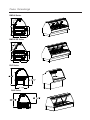
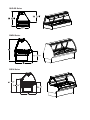
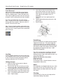
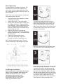
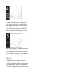
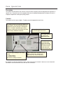
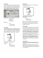
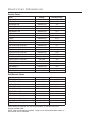
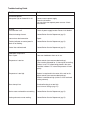
Service & Installation Instructions
Keep this booklet for Future Reference
BMDH SERIES
BSDH SERIES
DLPH SERIES
SMDH SERIES
SSDH SERIES
QHD SERIES
For Additional Copies Please Contact:
Hillphoenix Barker Specialty Products
703 Franklin Street
P.O. Box 478
Keosauqua, Iowa 52565
Tel: 319/ 293-3777
Fax: 319/ 293-3776
Or Visit:
www.hillphoenix.com
Updated 09/23/11
Table of Contents
General Information
Maintenance Information
Case Descriptions - - - - - - - - - - - - - - - - - - - - -3
Shipping Information - - - - - - - - - - - - - - - - - - -3
Case Sections
BMDH Series - - - - - - - - - - - - - - - - - - - - - - -4
BMDH SS Series - - - - - - - - - - - - - - - - - - - -4
DLPH Series
QHD Series - - - - - - - - - - - - - - - - - - - - - - - -4
QHD SS Series - - - - - - - - - - - - - - - - - - - - -5
SMD Series - - - - - - - - - - - - - - - - - - - - - - - -5
SSD Series - - - - - - - - - - - - - - - - - - - - - - - -5
Cleaning - - - - - - - - - - - - - - - - - - - - - - - - - - -13
Case Exterior - - - - - - - - - - - - - - - - - - - - - - -13
Case Interior - - - - - - - - - - - - - - - - - - - - - - - -13
Troubleshooting Guide - - - - - - - - - - - - - - - -14
Service Department - - - - - - - - - - - - - - - - - - -15
Parts - - - - - - - - - - - - - - - - - - - - - - - - - - - - -15
Warranty - - - - - - - - - - - - - - - - - - - -16
Installation Instructions
Crate Removal - - - - - - - - - - - - - - - - - - - - - - -6
Leveling - - - - - - - - - - - - - - - - - - - - - - - - - - - -6
Joining Lineups - - - - - - - - - - - - - - - - - - - - - - -6
Field Wiring - - - - - - - - - - - - - - - - - - - - - - - - -6
Doors - - - - - - - - - - - - - - - - - - - - - - - - - - - - - -6
Cleaning - - - - - - - - - - - - - - - - - - - - - - - - - - -6
Glass Adjustment - - - - - - - - - - - - - - - - - - - - -7
Cart Bumper Installation - - - - - - - - - - - - - - - -7
Case Operation
Description - - - - - - - - - - - - - - - - - - - - - - - - - -9
Controls - - - - - - - - - - - - - - - - - - - - - - - - - - - -9
Preheating - - - - - - - - - - - - - - - - - - - - - - - - -10
Load Limits - - - - - - - - - - - - - - - - - - - - - - - - -10
Product Display - - - - - - - - - - - - - - - - - - - - - -11
Common Settings - - - - - - - - - - - - - - - - - - - -11
Unit Shutdown - - - - - - - - - - - - - - - - - - - - - -11
Electrical Information - - - - - - - - - - - - - - - - - -12
IMPORTANT!!
KEEP FOR FUTURE REF ERENCE
General Information
This booklet contains information on:
BMDH Series
Hot service or self-service deli merchandiser
BSDH Series
Hot service or self-service deli merchandiser
QHD Series
Hot service or self-service countertop deli merchandiser
DLPH Series
Hot service deli merchandiser
SMDH Series
Hot service deli merchandiser
SSDH Series
Hot service deli merchandiser
The merchandisers in the manual conform to the following standards
Shipping Information
IMPORTANT!
FOR YOUR PROTECTION PLEASE READ AND OBSERVE THE FOLLOWING INSTRUCTIONS:
Transportation companies assume all liability from the time a shipment is received by them until the time it is
delivered to the consumer. Our liability ceases at the time of shipment.
All shipments leaving our plant have been carefully inspected. If a shipment arrives with the crating or packaging damaged, have the carrier note the condition on the receipt. Check as soon as possible for concealed
damage.
If it is found that the shipment has been damaged in transit, please DO NOT return it to us, but notify and file a
claim with the carrier at once. FAILURE TO FOLLOW THIS PROCEDURE WILL RESULT IN REFUSAL BY
THE CARRIER TO HONOR ANY CLAIMS WITH A CONSEQUENT LOSS TO THE CONSUMER.
If a UPS shipment has been damaged, retain the damaged material and the carton and notify us at once. WE
will file a claim.
GOODS SHOULD NOT BE RETURNED FOR CREDIT UNLESS AUTHORIZED BY OUR SALES DEPARTMENT.
Case Drawings
BMD-H Series
BMD-H SS Series
DLP Series
QHD Series
QHD-SS Series
SMDH Series
SSDH Series
Installation Instructions
Crate Removal
5.
Move case as close as possible to its permanent
location. Remove all crating and shipping braces
above the shipping pallet. Loosen the plastic dust
cover from the pallet, but leave cover over the case
to protect it while removing the case from the pallet.
This case may be fitted with 4 or more leveling
pads. Carefully lift the case up and off the pallet so
leveling pads clear the pallet. When the case is in
location, remove the dust cover.
6.
7.
Level case so that the screw holes in the
joining plate located at the top of the case
align over the screw holes of the adjoining
case. Adjust leveling pads or shim as
necessary.
THE FRONT OF THE CASES MUST BE
FLUSH!
Tighten bottom bolts tightly and screw in top
joining plate.
Seal all seams
Note: Locate horizontal supports underneath of unit
before removing from pallet. Damage to the finished
metal will occur if correct lift points are not identified
prior to removal.
Field Wiring
Electrical connections are made through the power
supply box of each case. The power supply box
can be accessed in the rear raceway. Electrical
requirements can be found in the electrical information section on page 10 but always check the data
tag located on the exterior of the case. CASE
MUST BE GROUNDED.
Leveling
To ensure proper operation, the case must be level.
Use a carpenter level to level front to back and side
to side. If fitted with leveling pads adjust pads as
necessary otherwise shim as necessary.
Joining Lineups
1.
2.
3.
4.
Begin all lineups leveling from the highest
point of the store floor.
Remove front and rear toe kicks by removing
screws on all sides. Set and level first case.
Level second case to first case and seal with a
good grade silicone on all edges of each case.
Slide cases together, lining up the bottom bolt
holes. Insert bottom bolts and place nuts on
bolts. Tighten slightly.
This case must be wired in accordance with local
codes, or in the absence of local codes, with the
National Electrical Code, ANSI-NFPA 70-1990. You
can get this code from:
National Fire Protection Association
Batterymarch Park
Quincy, MA 02269.
For European Union: All pole disconnect must be
incorporated in fixed wiring.
Doors
Rear load doors are shipped inside the case. Push
top of doors all the way into top door tracks. Push
bottom of door over bottom door tracks and lower
over tracks.
Cleaning
Clean the interior of the case with soap and hot
water before loading with product.
Glass Adjustment
The front lift glass is installed at the factory. The
installation site may not have completely level
floors, which may make glass adjustments necessary. Before adjusting glass, make sure case is as
level as possible
NOTE: This is a 2-person operation. One person
must hold the glass at all times.
1.
2.
3.
4.
5.
6.
7.
Lift the glass to its highest position as shown
in drawing to the below.
Loosen allen screws. (See profile below.)
Starting at the right side, tap the wedge with a
#2 standard screwdriver. Repeat procedure
on the left side. Continue working right to left
until the wedge recesses into the aluminum
extrusion. Extreme care must be taken not to
tap the wedge too hard.
Slide the glass right or left as needed.
Tighten the right allen screw while holding the
left side of the glass firmly. Be careful to keep
the glass level.
Tighten the remaining allen screws.
Lower glass into position. Repeat as
necessary until glass is completely level.
Cut plastic base to desired length of fixture.
When using end caps be sure to cut base 3/4”
short of fixture edge. When using corners, be
sure to cut base so that it is flush with fixture
edge. secure base to fixture with screws every 4”
on center. Make sure to put a screw 3/8” away
from the cut end of base.
NOTE: Do not stand on top of case. This may
result in personal injury and damage to the case.
SNAP end caps or corners onto the base extrusion. Secure with #8 flat head phillips screws.
Cart Bumper Installation
Note: If equipment is ordered with cart bumper,
steps 1 & 2 are completed at the factory and
installer should skip to steps 3 , 4 and 5.
Tools required: Tape measure, pencil,
drill with phillips driver bit, rubber mallet,
straight edge, chalk line, PVC cutters,
cotton rags, non-abrasive cleaner
When installing flexible bumper top, the cut ends
need to be as straight as possible. To mount on
a curved or flat surface, start at one end and
attach bumper to base by hooking bumper top
onto track, then snap bottom portion into place
and slide bumper against the end cap for a flush
fit. Continue to hook bumper onto base track with
your hand or using a rubber mallet until you
reach other end cap. NOTE: Cover mallet with a
cloth to prevent marring the bumper finish.
Mark and cut tail end of flexible bumper at least
1/8” longer then beyond the end cap position.
NOTE: Make sure the end cut is straight and
square for proper fit. Slightly retract the bumper
in order to feed cut end into the end cap as you
finish hooking the top and bottom edges of the
bumper onto the base track. You should feel and
hear the bumper snap into place for a snug fit.
Finally, check for proper fit and attachment along
the entire length of bumper which is either on the
wall or a fixture. Make sure you have a smooth
and flush fit against the end caps. NOTE: Clean
any dust or debris with a cloth and non abrasive
cleaner.
Helpful Hints:
• Set the uncoiled flexible vinyl at room
temperature 24 hours prior to installation.
• Over cut the flexible vinyl and compression fit.
Adding the additional material will compensate
for stretching which occurs during installation.
• Use a clean, dry cloth and any mild household
cleaner or soap solution; spray and wipe clean
Case Operation
Description
The controls and elements of this case are unique to Barker Company and are designed to be operated in a
specific way. Using this case for any purpose other than for holding heated product for display will result in
improper temperatures and/or poor quality product.
Controls
The controls on this case are digital. To adjust, press the appropriate arrow firmly.
The heating element LED turns on and off once
every second. The Heat Active dot blinks on
and off each time the element is switched on
and off. If the dot is not blinking,(it is either
always on or always off), the control has failed
and the factory should be contacted.
The top light is for illumination only.
It is not the upper heat source.
Turn Power ON/OFF
by pressing the
appropriate button.
When the controls
are off, the main
power light should
still be lit. If it is not,
the electrical circuit
to the case is off
and should be reset.
This is the digital reading of the setting.
0 = Off
1 = Lowest Setting
9 = Highest Setting
See common settings for details
Adjust heating levels by pressing up or
down arrows for five seconds, the
adjusting to the correct temperature.
The controls are normally grouped in clusters. Each case will have Control #1 and one or more Control #2.
Combination service/self-service cases will also have Control #3.
Control #1
Control #3
This is the largest control. Once settings are determined, use this control to turn power on and off for
the case. Controls will return to their previous setting, eliminating the need to set daily. Reset when
ambient conditions change or product changes.
This control is only present in a combination service/self-service case.
FUNCTIONS:
Case power on/off
Lights on/off
Top fan on/off
Overhead heat
RANGE: 0-9
0 = off
1 = lowest setting
9 = highest setting
FUNCTIONS: Overhead heat
RANGE: 0-9
0 = off
1 = lowest setting
9 = highest setting
NOTE: Service Cases do not have an overhead
heat source, only self-service cases or the selfservice portion of a combination case will have an
overhead heat source.
Preheating
Control #2
This is the largest control. Once settings are determined, use this control to turn power on and off for
the case. Controls will return to their previous setting, eliminating the need to set daily. Reset when
ambient conditions change or product changes.
Turn on power switch and set controls to level 9 for
preheating. Place empty pans or tiles in all wells.
Let unit operate with empty pans or tiles for 90 minutes before loading with product. Adjust controls to
desired levels before loading case with product
(See Common Settings page 10). Putting hot food
in a case that has not reached full temperature will
cause product temperature to drop quickly. All
product must be preheated to 175° F. It is essential
that product be fully cooked and heated prior to
stocking the case. Check product temperature of
larger pieces when cooking different size items. It
takes longer for larger pieces to reach the desired
temperature.
Load Limits
FUNCTIONS:
RANGE:
Well control
0-9
0 = off
1 = lowest setting
9 = highest setting
Product must be 6" below the top heater in selfservice cases. Product must be contained to the tile
or well area.
Product must be placed in the center of the well.
WELLS MUST BE COMPLETELY COVERED WITH
TILES OR PANS WHETHER FILLED WITH PRODUCT OR EMPTY.
Product Display
Unit Shutdown
Product should be arranged by product type. For
best results group like product together. If product is
stacked in a self service case, lower top heater setting for best results.
This merchandiser is designed to operate without
water in the well. Adding water will cause the case
to expend too many BTU's to heat the water and
not the product and may also cause condensation
to collect on front glass of service cases.
Turn case power to off on Control #1. It is not necessary to adjust well or overhead heat controls.
Remove product. Turn off case lights. Allow case
to cool completely before cleaning.
Common Settings
Product that is immersed in liquid is easier to keep
hot. Fried foods are the hardest to maintain temperature.
To adjust temperatures, change the setting, one
number at a time. Allow 1-2 hours for the case temperature to even out before continuing.
The settings will need to be adjusted to your product format and store conditions. Use these settings
as a starting point.
Once the correct setting is found, the controls may
be left at that setting and turned OFF and ON using
the power switch on the main control. The case
must be turned on 1½ hours before setting product.
Wells must be covered with empty pans or tiles.
NOTE: This case is designed to display and hold
product temperature. Although this case is capable
of raising product temperature, it is not recommended. Stock with preheated product only.
Case Air Temperature
The case air temperature may not be as high as the
desired product temperature. This case is designed
to produce long wave radiant heat. It penetrates
the food and keeps it warm from the inside out.
The air temperature, therefore, may not be the
same as the product temperature. Measure product
interior temperature to determine the correct settings, not the air temperature.
Electrical Information
Service Cases
Model
Voltage
Total Amperage
BMDH/BSDH-4S
120-208-3-60
5.3
BMDH/BSDH-5S
120-208-3-60
8.5
BMDH/BSDH-6S
120-208-3-60
8.5
BMDH/BSDH-8S
120-208-3-60
12.0
BMDH/BSDH-10S
120-208-3-60
14.1
BMDH/BSDH-12S
120-208-3-60
17.3
DLPH-4
120-208-3-60
7.02
DLPH-6
120-208-3-60
11.46
DLPH-8
120-208-3-60
15.11
DLPH-10
120-208-3-60
18.51
DLPH-12
120-208-3-60
22.96
QHD-3S with 20" Deep Well
120-208-3-60
6.7
QHD-4S with 20" Deep Well
120-208-3-60
8.8
QHD-5S with 20" Deep Well
120-208-3-60
6.8
QHD-6S with 20" Deep Well
120-208-3-60
9.18
QHD-8S with 20" Deep Well
120-208-3-60
12.6
QHD-4S with 27" Deep Well
208-3-60
6.7
QHD-6S with 27" Deep Well
208-3-60
8.8
SSDH/SMDH-4
120-208-3-60
5.3
SSDH/SMDH-6
120-208-3-60
8.5
SSDH/SMDH-8
120-208-3-60
12.0
SSDH/SMDH-10
120-208-3-60
14.1
SSDH/SMDH-12
120-208-3-60
17.3
Self-Service Cases
Model
Voltage
Total Amperage
BMDH/BSDH-4SS
120-208-3-60
6.95
BMDH/BSDH-5SS
120-208-3-60
9.00
BMDH/BSDH-6SS
120-208-3-60
10.96
BMDH/BSDH-8SS
120-208-3-60
15.29
BMDH/BSDH-10SS
120-208-3-60
18.23
BMDH/BSDH-12SS
120-208-3-60
22.18
QHD-3SS with 20" Deep Well
208-1-60
6.7
QHD-4SS with 20" Deep Well
208-1-60
8.8
QHD-5SS with 20" Deep Well
208-1-60
6.8
QHD-6SS with 20" Deep Well
208-1-60
9.18
QHD-8SS with 20" Deep Well
208-1-60
12.6
Unless otherwise requested, this unit will be wired for (1) 120-208-3-60 circuit.
All units are hard wired.
NOTE: Case runs on 208V, three phase. Lights run on 120V and therefore require an
extra neutral wire for installation.
Maintenance Information
Cleaning
Unit should be thoroughly cleaned at the end of
each day.
Case Exterior
Clean surfaces frequently with warm water and mild
detergent. DO NOT use strong alkali solutions,
steel wool, or abrasive cleanser. Be careful of any
electrical outlets located on the rear of the case.
Cleaning Cloths
Scotch-Brite High Performance Cloth - manufactured by 3M® and available in most grocery stores
under the name Scotch-Brite® Microfiber Cleaning
Cloth in a 12" x14" size. This cloth is washable and
may be reused as long as it remains clean.
Spontex® Microfibre Cleaning Cloth - distributed
by Spontex® and available in most grocery stores
under the same name in a 15.75" x 12" size. This
cloth is washable and may be reused as long as it
remains clean.
The cleaning cloths named above will normally
remove dust, grease, oil and fingerprints without the
need for cleaning fluids. A light spray of the cleaning fluids listed below will reduce the time required
for cleaning.
Cleaning Fluid - for more difficult cleaning jobs,
these products are recommended:
Windex® - standard product only (extra-strength or
specialty products may not be suitable)
Glass-Plus® - standard product only (extra-strength
or specialty products may not be suitable)
Warm Water
DO NOT USE the following types of materials for
cleaning glass with anti-reflective coatings.
Coarse Paper Towels
Scouring Pads or Powders
Steel wool or Steel Fiber Materials
Blades
Acidic or highly Alkaline detergents
Fluorine based detergents
Case Interior
Clean interior with warm water and a mild detergent. A sanitizer should be used after washing to
eliminate bacteria. Avoid spraying water directly
into electrical connections. Keep doors open until
completely dry.
Preventative Maintenance
1. Read the Installation and Service manual.
2. Clean the case daily.
3. See the trouble shooting guide in the event of
problems.
4. Contact Barker Company for an authorized
service person in your area.
Troubleshooting Guide
Problem:
Unit fails to operate
Main power light on Control #1 is off.
Action:
Connect case to power supply.
Reset circuit breaker.
Unit may have two separate power sources. Check
both sources.
No Heat
Circuit breaker is off.
Check all power supply breaker. Reset circuit breaker.
Defective heating element.
Contact Barker Service Department (pg 15).
Loose wire or bad connection.
Repair.
Flashing indicator on control panel is
blank or not flashing.
Contact Barker Service Department (pg 15).
Control has malfunctioned.
Contact Barker Service Department (pg 15).
Inadequate Temperature
Door is open.
Close rear load doors when not in use.
Temperature is too low.
Adjust controls (see recommended settings).
Case must be preheated for 1½ hours prior to stocking.
Product is not 175° before being placed in the case.
Food that is below 175° internal temperature will cool
quickly.
Temperature is too high.
Product is not placed in the center of the well or tile.
Adjust controls (see recommended settings).
Product is stacked too high (within 6" of the overhead
heating element).
Glass clamp is hot.
Overhead heating is set too high
(see Common Settings page 10).
Service case overhead fan not working
Contact Barker Service Department (pg 15).
Heating elements are not working.
Contact Barker Service Department (pg 15).
Hillphoenix Barker Specialty Products Service Department
IMPORTANT INFORMATION!
FOR PROMPT SERVICE WHEN CONTACTING THE FACTORY FOR SUPPORT, BE
SURE TO HAVE CASE MODEL AND SERIAL NUMBER HANDY.
(THIS INFORMATION IS LOCATED ON THE DATA TAG ATTACHED TO THE CASE. SEE BELOW FOR DATA TAG LOCATIONS)
For any warranty or service issues not covered by this manual, for tech support, or for warranty service calls, please contact the Barker Specialty Products
Service Department at:
(319) 293-3777
Parts
Ordering Procedure
1.
Contact the Service Parts Department
Melissa Marshall
703 Franklin Street
PO Box 478
Keosauqua, IA 52565
Tel: 319-293-8323
Fax: 319-293-8377
[email protected]
2.
Provide the serial number of the case containing the part.
To locate the serial number look on the data tag located on the
customer left, outside back of the case, the customer left, inside
top of the case, or contact the factory for location.
3.
If parts are to be returned for credit, contact the Parts
Department. Do not send parts without authorization.
BEFORE SERVICING
ALWAYS DISCONNECT ELECTRICAL
POWER AT THE MAIN DISCONNECT
WHEN SERVICING OR REPLACING
ANY ELECTRICAL COMPONENT.
WARRANTY
HEREINAFTER REFERRED TO AS MANUFACTURER
FOURTEEN MONTH WARRANTY. MANUFACTURER’S PRODUCT IS WARRANTED TO FREE FROM DEFECTS IN MATERIAL
AND WORKMANSHIP UNDER NORMAL USE AND MAINTENANCE FOR A PERIOD OF FOURTEEN MONTHS FROM THE DATE
OF ORIGINAL SHIPMENT. A NEW OR REBUILT PART TO REPLACE ANY DEFECTIVE PART WILL BE PROVIDED WITHOUT
CHARGE. PROVIDED THE DEFECTIVE PART IS RETURNED TO MANUFACTURER. THE REPLACEMENT PART ASSUMES THE
UNUSED PORTION OF THE WARRANTY.
WARRANTY CLAIMS: All claims should include: the serial number of the cabinet, proof of purchase, date of installation,
and all pertinent information supporting the existence of the alleged defect. Any action for breach of these warranty provisions must be commenced within one (1) year after that cause of action has accrued.
All warranty service work must be pre-authorized by Barker Specialty Products (800-814-0446). Barker Specialty
Products reserves the rights to designate the service provider, time in which labor is to be performed and specify amount
of time per warranty problem.
This warranty does not include labor or other costs incurred for repairing, removing, installing, shipping, servicing or handling of either defective parts or replacement parts.
The fourteen month warranty shall not apply:
1.
To any unit or any part thereof which has been subject to accident, alteration, negligence, misuse or abuse,
operation on improper voltage, or which has not been operated in accordance with the manufacturer’s
recommendation, or if the serial number of the unit has been altered, defaced, or removed.
2.
When the unit, or any part thereof, is damaged by fire, flood, or other act of God.
3.
Outside the continental United States.
4.
To labor cost for replacement parts, or for freight, shipping expenses, sales tax or upgrading.
5.
When the operation is impaired due to improper installation
6.
When installation and startup forms are not properly complete or returned within two weeks after startup.
THIS PLAN DOES NOT COVER CONSEQUENTIAL DAMAGES. Manufacturer shall not be liable under any circumstances for
any consequential damages, including loss of profit, additional labor cost, loss of any delay in its performance hereunder
due to causes beyond its control. The foregoing shall constitute the sole and exclusive remedy of any purchases and the
sole and exclusive liability of Manufacturer in connection with this product.
The Warranties are Expressly in Lieu of All Other Warranties, Express of Implied and All Other Obligations or Liabilities on
Our Part. The Obligation to Repair or Replace Parts or Components Judged to be Defective in Material or Workmanship
States Our Entire Liability Whether Based on Tort, Contract or Warranty. We Neither Assume Nor Authorize any Other
Person to Assume for Us Any Other Liability in connection with Our Product.
Mail approved warranty claims to the address listed below:
Hillphoenix Barker Specialty Products
703 Franklin Street, PO Box 478
Keosauqua, IA 52565
Tel: 319-293-3777/Fax: 319-293-3776