1
SuMegha Cloud Lab Kit
Version 1.3
User Manual
10th Oct 2013
System Software Development for HPC
C-DAC KP
Bangalore
1
SuMegha Cloud Lab Kit
Version 1.3
User Manual
Project No: CDACB/SSDH/CSC/2013/
Document No: SSDH/SuMegha/2013/LabKit/User manual/1.3
Control Status: Controlled (For External users mentioned in Distribution List)
Authors : Sukeshini, Payal Saluja, Shivay Veer Sharma, Deepanshu Saxena,
Distribution List :
Engineering Colleges and Research Organisations
Name
Approved By
Signature
Dr. B B Prahlada Rao
Designation
Date of Approval
Joint Director, SSDH,
CDAC, Bangalore
Release By : SSDH, C-DAC Knowledge Park, Bangalore
Date of Release :
Copy No. : 1
2
Contents
Chapter 1 - Introduction ………………………………………………………………..…… ...4
1.1 Cloud Computing ...………………………………………………………………….…..4
1.2 SuMegha Cloud Lab kit …………...………………………………………..…………..6
Chapter 2 - SuMegha Cloud Stack …………………...………………………………….……..7
2.1 SuMegha Cloud Stack Components ……………...…………………………………....7
2.2 SuMegha Lab Kit Offerings .……………………………………………………………8
Chapter 3 – Installations and Configurations …….……………………………….…………10
3.1 Prerequisites for Installations …………………………………………………...…….10
3.2 Common Configurations …………………………………………………………...….10
3.3 Cloud Lab Kit Software Installations ………………………………………………...13
3.3.1 Virtual Machine Manager (VMM) Node Installation …………………………14
3.3.2 Service Node Installation ………………………………………………………..20
Chapter 4 – Using Cloud Services …….……………………………….……………...…….. 24
4.1 Configurations …………………...…………………………………………………………24
4.2 Virtual Machines ………………………………………………………………………… 24
4.3 Login to Virtual Machines ………………………………………………………………...26
4.4 Virtual Clusters ……………………..…………………………………………………….. 27
4.4.1 Creation of Message Passing Interface (MPI) Cluster ………………………...28
4.4.2 Creation of Hadoop Cluster ……………………..………………………………28
Chapter 5 – Getting Started …….……………………………….………………….……….. 30
5.1 Job Submission Portal…………………………………………………..……………….…30
5.2 Problem Solving Environment (PSE) for SFM ……………………………..……………33
List of Figures
3
Chapter 1
Introduction
1.1 CLOUD COMPUTING
Cloud Computing is the buzz word in today’s technological era. The researchers,
academicians and domain experts who want to build a private cloud for their applications, don’t
know where and how to start. The SuMegha Cloud Lab kit becomes an ideal solution to cater
their requirements. SuMegha is a C-DAC’s scientific cloud with various open- source and
indigenously developed components installed to facilitate the users to execute their applications
on cloud with ease.
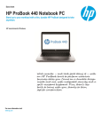
Figure 1: Cloud computing layers
Cloud Computing is delivery of Computing as a Service rather than a product, wherein
resources, software(s) and information are provided as a utility (like the electricity) over Internet.
Cloud computing use the Internet technologies for delivery of IT Enabled capabilities ‘as a
service’ to the required users. We can access these resources from anywhere and pay according to
our usage. The services offered on cloud are:
SaaS (Software as a Service) - The users are given access to software applications
hosted by the cloud vendor over Internet.
Examples: Cloud-based word processing application, Online e-mail providers like
Google’s Gmail, Yahoo mail and Microsoft Hotmail, Photo editing softwares, Google
docs etc.
PaaS (Platform as a Service) – It offers development platform on the cloud. Provider
manages the cloud infrastructure for the platform and users can develop and host their
applications on cloud. The entire life cycle of software can be operated on a PaaS.
4
Example: Google App Engine lets users run web applications on Google's infrastructure.
IaaS (Infrastructure as a Service)–It is on demand provisioning of Virtual Machines,
Virtual Clusters, and Storage (StaaS – storage as a service) to users. The main concept
being virtualization, where the users through their virtual desktop access resources like
Network, Storage, Virtualized Servers, Routers and so on, supplied by Cloud Service
Provider (CSP).
Examples: Amazon EC2 and Amazon S3 (Storage as a Service).
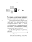
Following are the common deployment models of cloud:
Figure 2: Cloud computing types
1. Public clouds: The services and infrastructure in a Public Cloud are provided off-site
over the Internet that is open for public use. Usually, they are owned by the organization
offering the cloud services.
2. Private clouds: A private cloud is one in which the services and infrastructure are
maintained on a private network and is operated solely for one organization. These clouds
offer the greatest level of security and control.
3. Hybrid clouds: A hybrid cloud is a composition of two or more clouds (private or public)
and includes a variety of public and private options with multiple providers.
Scientific Clouds
Scientific computing deals with solving large-scale scientific problems in domains like
astrophysics, mechanical engineering and material science by utilizing mathematical modeling
and computer simulations. Running large and accurate simulations requires a significant amount
of computing resources, often demanding the utilization of supercomputers, Clusters or Grids;
which may not be available for the researchers and scientists. Scientific Clouds can meet these
huge computation capabilities and storage requirements of scientific community through
5
infrastructure and storage services that can be shared with the scientists and researchers over
Cloud. Amazon Elastic MapReduce is an example that gives processing capability for vast
amounts of data stored over amazon S3 service. SuMegha is a scientific cloud, developed by CDAC, offers High Performance Compuitng (HPC) as a service, Infrastructure as a Service and
Storage as a Service.
1.2 SUMEGHA CLOUD LAB KIT
SuMegha Cloud lab kit is a sophisticated Cloud installation package comprising of
various softwares to build private clouds. The Cloud software stack consists of open source
components like Xen, Nimbus, Openstack swift, GlusterFS and in-house developed tools like
Cloud portal, Problem Solving Environments (PSE), Cloud Vault, Job Submission portal. It also
provides a set of Golden Images of different sizes like small, medium, and large; with CentOS
operating systems and parallel environments with MPI libraries and Hadoop framework. This lab
kit enables the automated deployment (installation and configuration) of private cloud on the
recommended hardware to setup “Cloud Lab” without having expertise in system administration.
Highlights
Builds a private cloud in an organization
Web based tools that supports easy and quick access to the Virtual machines and
Virtual HPC clusters
Simple and quick installation of all the cloud components.
Pre-built OS images with complex parallel environments like MPI and Map Reduce to
cater the HPC needs.
Golden images with preloaded HPC applications like Seasonal Forecast Model, Cloud
Next generation pipeline with the required visualization tools and job submission
portal for easy parallel job submission.
Who can use SuMegha Cloud Lab Kit?
Entry Level Engineers
o To get better understanding of basics, necessary functions and features of
SuMegha before working on Real-time environment
Educational/ Training Institutes
o To setup Cloud laboratory for experimental / practical purpose.
Research Organizations
o To identify issues and vulnerabilities of important aspects in Cloud Computing,
such as Monitoring, Security, Resource usage, Billing, etc.
6
Chapter 2
SuMegha Cloud Stack
2.1 SUMEGHA CLOUD STACK COMPONENTS
SuMegha Cloud Stack has been designed, keeping in mind the requirements of the
scientific environments and applications. The stack comprises of the stable versions of best
suited Cloud components required to build the private scientific cloud. Figure 1 depicts the
complete SuMegha software stack.
The basic SuMegha Cloud lab kit consists of the following components:
OS (CentOS) : Downloadable from SuMegha website (www.Sumegha.in)
Hypervisor (Xen): CD
Cloud Middleware (Nimbus):CD
Cloud Portal
Pre-built golden images with CentOS, MPI & HADOOP environments and tools
like job submission portal for virtual HPC clusters.
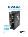
Figure 3: SuMegha Cloud Stack
7
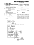
Figure 4 shows the architecture of Cloud components installed using SuMegha Cloud Lab kit.
Figure 4: SuMegha Cloud Architecture
2.2 SUMEGHA LAB KIT OFFERINGS
Basic Cloud lab kit (Free) --- Currently available
a. Software stack to setup Private cloud for provisioning of Virtual Machines/
Servers i.e deployment of Infrastructure as a Service
b. Interactive installation & configuration of cloud stack
c. User manual for SuMegha Cloud lab kit.
d. Distribution through CD and downloadable from SuMegha website
(www.sumegha.in)
Basic Cloud lab kit with Cloud Storage facility upto 2 GB (Free) --- In future
a. Software stack to setup Private cloud for provisioning of Virtual Machines/
Servers i.e deployment of Infrastructure as a Service (IaaS)
b. Interactive installation & configuration of cloud stack
c. User manual for SuMegha Cloud lab kit
d. Access to Cloudvault cloud storage: up to 2 GB free, beyond it chargeable per
5GB
e. Distribution through CD
Advanced Cloud lab kit (Chargeable) --- In future
a. Software stack to setup Private cloud for provisioning of Virtual Machines/
Servers i.e deployment of Infrastructure as a Service (IaaS)
b. Interactive installation & configuration of cloud stack
c. Software stack to setup cloud storage (Storage as a Service – StaaS)
d. Access to Cloudvault cloud storage: Upto 5GB
e. User manual for SuMegha Cloud lab kit
8
f. 1-day hands-on training
g. Distribution through CD
Support Services
E-mail support (free)
Annual maintenance through E-mail support (Chargable)
One day hands-on training (chargable)
9
Chapter 3
Installation & Configuration
3.1 PREREQUISITES FOR INSTALLATION
It is assumed that the installer possess the knowledge of basic UNIX system administration.
Following are requirements to set up the Virtual Machine Manager (VMM) node and Service
Node, as part of SuMegha Cloud Lab Kit installation.
3.1.1 Virtual Machine Manager (VMM) Node
Operating System
Centos version 6.4
Downloadable from linkhttp://www.sumegha.in/Repository/CentOS_6.iso
CPU
One or more 64-bit x86 CPU(s),
1.5 GHz or above,
2 GHz or faster multi-core CPU recommended
RAM
Disk Space
Minimum 4 GB
Minimum 60 GB; Minimum 2GB for /boot partition
3.1.2 Service Node
Operating System
RAM
Disk Space
Centos 6.4
4 GB
Minimum 100 GB
Network
Internet Connectivity
Software
JAVA 1.6+, Python (2.6 – 3.0)
3.2 COMMON CONFIGURATIONS
Before installations, the administrator must check for three things on the both VMM node
and Service node:
1. Disable the SELINUX
2. Disabling "requiretty" setting
3. Providing sudo privileges to nimbus user
10
Disable the SELINUX
By default, SELINUX is enforcing. The user has to disable the SELINUX in the file:
"/etc/selinux/config". Please remove enforcing and add the entry: SELINUX=disabled
Disabling "requiretty" setting
In the file “/etc/sudoers”, discard the requiretty entry. Do not comment the line, instead
delete the requiretty entry.
Providing Sudo privileges to nimbus user
In the file “/etc/sudoers”, please add "nimbus" user the sudo privileges. Add entry:
‘nimbus
ALL=(ALL) NOPASSWD: ALL
Configuration: Virtual Machine Manager (VMM) Node
Before proceeding, please enable the virtualization in the BIOS setting.
11
For Intel processors: Go To Advanced Tab -> CPU Configuration-> Intel Virtualization > Enabled
For AMD processor: Go to System options -> Processor Options -> Amd Virtualization > Enabled
12
3.3 CLOUD LAB KIT SOFTWARE INSTALLATION
SuMegha installation is completely automated with minimal interactions with the user
installing the software. Also, ensure if all the pre-requisites are met before installation. The
installer is available in CD or can be downloaded from SuMegha website:
http://www.sumegha.in/Repository/SuMeghaLabKit.iso
If the installation is done from CD, execute the SuMegha-Install script present in the
main CD directory, using the command:
sh SuMegha-Install
If the installation is done from downloaded .iso, follow these steps:
a. # mount –o loop SuMeghaLabKit.iso <mount directory>
b. # cd <mount directory>
c. SuMegha installation is invoked by executing the following script present in main the CD
directory:
sh SuMegha-Install
When you invoke the main script SuMegha-Install, the options to install VMM node or
Service Node shall be displayed.
13
Note: VMM node should be installed & configured first, followed by the Service node.
3.3.1 Virtual Machine Manager (VMM) Node Installation
When the pre-requisites are met and VMM node installation option selected, the first
component of SuMegha Cloud Lab kit, Xen installation starts. The user is prompted whether to
create a default Network Bridge "xenbr0" or not.
At any point, when the installation has paused, please press “Enter key” twice to
continue.
If user opts for default Xen bridge creation, then he/ she has to provide IP Address,
Gateway Address, DNS Address and the name of the Interface on which network is configured.
14
It will create Xenbr0 Bridge and it will restart the network
After bridge gets created, installation of Xen, its relative packages and libvirt begins.
15
After the Xen is installed successfully, check the default variable in the file
"/boot/grub/menu.lst" before rebooting. Change the default kernel to Xen Kernel, by changing
the value of the default variable.
Creating your own Network Bridge
If the user opts for creating his/ her own Network Bridge, he/ she has to set up a network
bridge on their server for virtual machines to be accessed from other hosts, as if they were
16
physical systems in the network.
To do this, we install the package bridge-utils and configure a bridge.
yum install bridge-utils
Create the file /etc/sysconfig/network-scripts/ifcfg-br0
Please use the IPADDR, PREFIX, GATEWAY, DNS1 and DNS2 values from the file:
/etc/sysconfig/network-scripts/ifcfg-eth0file;
Also,
ensure
you
use TYPE=Bridge,
not TYPE=Ethernet
vi /etc/sysconfig/network-scripts/ifcfg-br0
DEVICE="br0"
NM_CONTROLLED="yes"
ONBOOT=yes
TYPE=Bridge
BOOTPROTO=none
IPADDR=192.168.0.100
PREFIX=24
GATEWAY=192.168.0.1
DNS1=8.8.8.8
DNS2=8.8.4.4
DEFROUTE=yes
IPV4_FAILURE_FATAL=yes
IPV6INIT=no
Modify /etc/sysconfig/network-scripts/ifcfg-eth0 as follows (Comment
BOOTPROTO, IPADDR, PREFIX, GATEWAY, DNS1, and DNS2 and add BRIDGE=br0)
vi /etc/sysconfig/network-scripts/ifcfg-eth0
DEVICE="eth0"
NM_CONTROLLED="yes"
17
ONBOOT=yes
HWADDR=00:1E:90:F3:F0:02
TYPE=Ethernet
#BOOTPROTO=none
#IPADDR=192.168.0.100
#PREFIX=24
#GATEWAY=192.168.0.1
#DNS1=8.8.8.8
#DNS2=8.8.4.4
DEFROUTE=yes
IPV4_FAILURE_FATAL=yes
IPV6INIT=no
NAME="System eth0"
UUID=5fb06bd0-0bb0-7ffb-45f1-d6edd65f3e03
BRIDGE=br0
Restart the network
/etc/init.d/network restart
Execute the following command:
ifconfig
It should now show the network bridge (br0):
br0
Link encap:Ethernet HWaddr 00:1E:90:F3:F0:02
inet addr:192.168.0.100 Bcast:192.168.0.255 Mask:255.255.255.0
inet6 addr: fe80::21e:90ff:fef3:f002/64 Scope:Link
UP BROADCAST RUNNING MULTICAST MTU:1500 Metric:1
RX packets:17 errors:0 dropped:0 overruns:0 frame:0
TX packets:29 errors:0 dropped:0 overruns:0 carrier:0
collisions:0 txqueuelen:0
RX bytes:1196 (1.1 KiB) TX bytes:2794 (2.7 KiB)
eth0
Link encap:Ethernet HWaddr 00:1E:90:F3:F0:02
inet6 addr: fe80::21e:90ff:fef3:f002/64 Scope:Link
UP BROADCAST RUNNING MULTICAST MTU:1500 Metric:1
RX packets:4554 errors:0 dropped:0 overruns:0 frame:0
18
TX packets:3020 errors:0 dropped:0 overruns:0 carrier:0
collisions:0 txqueuelen:1000
RX bytes:6249612 (5.9 MiB) TX bytes:254928 (248.9 KiB)
Interrupt:25 Base address:0x6000
lo
Link encap:Local Loopback
inet addr:127.0.0.1 Mask:255.0.0.0
inet6 addr: ::1/128 Scope:Host
UP LOOPBACK RUNNING MTU:16436 Metric:1
RX packets:3 errors:0 dropped:0 overruns:0 frame:0
TX packets:3 errors:0 dropped:0 overruns:0 carrier:0
collisions:0 txqueuelen:0
RX bytes:1304 (1.2 KiB) TX bytes:1304 (1.2 KiB)
Please execute command to switch off Network Manager at boot time “Chkconfig
NetworkManager off”
The VMM installation is complete. Please reboot your system with Xen kernel and check
whether installation is correct using following command: “virsh list”
[root@sumegha ~]# virsh list
Id Name
State
---------------------------------------------------0 Domain-0
running
The following output implies the system has booted with Xen kernel. Also, check using
“uname -r”.
Please uncomment following lines in /etc/libvirt/libvirtd.conf file:
Uncomment the line unix_sock_group=”libvirt” and replace ‘libvirt’ with ‘root’
unix_sock_group = "root"
Uncomment the following lines:
unix_sock_ro_perms = "0770"
unix_sock_rw_perms = "0770"
unix_sock_dir = "/var/run/libvirt"
auth_unix_ro = "none"
auth_unix_rw = "none"
After editing this file run the following command
usermod –G root nimbus
Restart libvirt and Xen service from ‘root’ login
service libvirtd restart
service xend restart
19
Checking Xen and libvirt
If VMM and Service Node are installed on the same machine, execute the following command to
check whether installations are correct:
virsh -c 'xen+ssh://nimbus@<service node-IP>' list
If VMM and Service Nodes are installed on different machines, execute the following command
to check whether installations are correct:
virsh -c 'xen+ssh://nimbus@<vmm node-IP>' list
If you encounter any errors, whether during installations or configurations, please report
to SuMegha team.
3.3.2 Service Node Installation
Select the Service Node installation option in the main script. The installations are done
in /opt/nimbus directory, by default. Ensure the output of the commands hostname and hostname
–f should be same.
Following are the steps for installing Service node:
1. Set up password less login using SSH keys to connect nimbus user of VMM and the Service
a. Generate an SSH keygen keys on the Service Node:
nimbus@service $ ssh-keygen –t rsa
b. Create .ssh directory on VMM node:
nimbus@vmm1 $ ssh nimbus@vmm1 mkdir -p .ssh
c. Upload the generated public keys to VMM node:
nimbus@service $ cat .ssh/id_rsa.pub |
ssh nimbus@vmm1 'cat >> .ssh/authorized_keys'
d. Set permissions on the VMM node:
Due to different SSH versions on servers, we need to set permissions on .ssh directory
and authorized keys file.
nimbus@vmm1 $ ssh nimbus@vmm1 "chmod 700 .ssh; chmod 640 .ssh/authorized_keys"
nimbus@vmm1's password: [Enter Your Password Here]
e. Login from Service Node to VMM Node without password
From now onwards, you can log into VMM node as nimbus user from the Service Node
20
as nimbus user without password.
nimbus@service $ ssh nimbus@vmm1
NOTE: As you add more VMMs in future, you should ensure that SSH works in the same way
for each.
2. While installing the Service node, the nimbus user is created. You have to press "y" to enable
it.
3. You have to provide the hostname of the machine where you have installed the VMM node.
If the VMM node is on same machine, you can provide "localhost" as shown below.
4. You have to provide the RAM size allocated for the VMM’s which shall be used for
virtualization.
5. Press "y" if the nimbus user is present on both Service and VMM Node.
6. Does the container account (nimbus) need a special (non-default) ssh key to access the
‘nimbus’ account on the VMM Node? Press “n”
7. All the VMMs should be able to access the Service Node by hostname. The hostname is
detected by the installation script and is shown in console. If the hostname is incorrect, then
press “no”; else provide correct hostname.
XXXX
8. By default, SSH Server runs on port 22.
If the VMM Node’s SSH port number is 22, don’t change the port number during installation,
by pressing "n". If ssh port number is other than 22, then provide the ssh port number.
9. If you have already installed the VMM Node, press [Enter] to continue.
21
10. For completing the installation, you need to explicitly start nimbus services when the script
prompts.
To start the nimbus services, login to another terminal as "nimbus" user and run following
command:
/home/nimbus/nimbus/bin/nimbusctl start
After these services start, press [Enter] in installation script.
11. If all the entries are correct, type "y" and press [Enter] when it prompt the message
12. After starting the service in other terminal, you should provide the list of IP’s required for the
Virtual Machines in the file:
/home/nimbus/nimbus/services/etc/nimbus/workspace-service/network-pools/public
# Hostname
IP Address
Gateway
Broadcast
Subnet Mask
[MAC]
pub3.cdacb.in
10.180.36.3
10.180.36.1
10.180.36.255
255.255.255.0
pub4.cdacb.in
10.180.36.4
10.180.36.1
10.180.36.255
255.255.255.0
pub5.cdacb.in
10.180.36.5
10.180.36.1
10.180.36.255
255.255.255.0
pub6.cdacb.in
10.180.36.6
10.180.36.1
10.180.36.255
255.255.255.0
pub7.cdacb.in
10.180.36.7
10.180.36.1
10.180.36.255
255.255.255.0
After adding these entries, restart the nimbus services. Also, add these entries in your
centralized DHCP server, in the file:
/home/nimbus/nimbus/services/var/nimbus/dhcpd.entries
Note:
All the administration commands are present in the directory: /home/nimbus/nimbus/bin
Two additional Scripts are provided in /home/nimbus directory for creating the user and
changing password
Cloud Portal is installed in /WebApplication (Tomcat Server)
Building the image repository
The images are required to boot the VM instances when requested by the user from cloud
portal. The steps for setting up the image repository are as follows:
1. Download the images from the following link:
http://www.sumegha.in/Repository/Images/
22
2. Switch user as “ nimbus”
Note: All the administrative commands should be executed as “nimbus” user
3. Run the following command as nimbus user to upload each image to the Cloud image
repository
/home/nimbus/nimbus-cloud-client-021/bin/cloud-client.sh --transfer --sourcefile
<image path> --common
This completes the installation of Service Node.
For any issues/ errors regarding the SuMegha Cloud Lab Kit installation, please contact the
SuMegha team for clarifications.
23
Chapter 4
Using Cloud Services
4.1 CONFIGURATIONS
Before starting the cloud services, you must ensure the following:
1. In Virtual Machine Manager (VMM) Node
Ensure the system is booted from the Xen Kernel
Check xend service is running
2. In Service Node
Providing IP addresses to Virtual Machines (VM) and centralized DHCP Server
Nimbus services are running
3. Configuration of Cloud Portal
Following
parameters
in
the
file:
/WebApplication/webapps/ROOT/WEBINF/classes/config.properties is modified as root.
Ipaddress = x.x.x.x
adminId=abc
adminPasswd=abc
If you face any issues while creating VMs through portal, please look into the file
/WebApplication/logs/catalina.out or contact SuMegha team.
4.2 VIRTUAL MACHINES
Refer Online help available in Cloud Portal for further details.
Create a Virtual Machine
To create a Virtual Machine, provide the following three parameters in the Run Instance
block on the Instance or Image page.
Image File - VM Type provided to you or VM’s saved by you.
Size
- RAM and CPU of your machine
Hours
- Number of hours you want the Virtual machine
24
The three variations in Image Sizes are:
Small Image
Medium Image - 2vCPU & 2GB RAM
Large
- 1 vCPU & 1GB RAM
- 4vCPU & 4GB RAM
Upon clicking the RUN button, the Virtual Machine is created and listed in the Instance page.
Following are the three states that Virtual Machine can be in:
UNPROPAGATED - your machine is in INSLALATION mode.
PROPAGATED - your machine is in BOOTING mode.
RUNNING - your machine is ready to use.
Save the Virtual Machine
You can save an instance of Virtual Machine by specifying the Image name and then
clicking on Save button in the Instances/ Images page.
Note: While saving, do not destroy the Virtual Machine; else you lose both your data and VM.
Also, you cannot save a Cluster.
Destroy the Virtual Machine
Click on the Destroy Machine block in the Instances / Images page and select the Virtual
Machine handle to be destroyed.
Note: You can destroy the machines at any point of time. Once you destroy the Virtual Machine,
the data in that machine also get destroyed.
Run the Saved Virtual Machine
When you save a Virtual Machine, it is listed in the Run Instances list on the Instances/
Images page. Specify the Image Size and the Number of Hours the image is required then click
RUN to start the machine using the saved image.
Delete the saved Virtual Machine
Click the Delete button next to the Image name in the list of saved images of the Virtual
Machine.
Note: If you delete a saved image, it does not delete the Virtual Machine with which it was
booted.
25
4.3 LOGIN TO VIRTUAL MACHINE
1. From Linux System
You can login to the Virtual Machine using the SSH key given at the home page by following
these steps:
Copy the SSH key content into a file
Change the mode of that file using the following command:
$chmod 0600 filename
Now, ssh using that key:
$ ssh -i {path of ssh key file} root@{machine IP address}
2. From Windows System
Step 1: Install putty client on your Windows desktop machine.
Step 2: Copy the ssh key from the Cloud Portal after registration and save text file on your
Windows desktop machine.
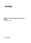
Step 3: Install puttygen. Using puttygen, as shown in Figure 5, convert ssh private key to .PPK
format compatible for putty. Click yes, when prompted for passphrase free ssh communication.
Figure 5: Puttygen - Convert ssh private key to putty compatible format
Step 4: Provide the IP address and Port number of the VM instance to be accessed.
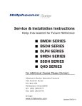
Step 5: Load the ssh private key as shown in figure 6 to open the session.
Step 6: Login as root user.
26
Figure 6: Putty - uploading ssh private key to login to the remote machine
4.4 VIRTUAL CLUSTERS
To create a Virtual Cluster, provide the following four parameters in the Run Cluster block
on the Instances/ Images page.
Type
Size
Node
- Number of Nodes required (including Head Node)
Hours
- Number of hours you want the Virtual Cluster
- Cluster type
- RAM and CPU of your Cluster
The three variations in Image Sizes are:
Small Image
Medium Image - 2vCPU & 2GB RAM
Large
- 1 vCPU & 1GB RAM
- 4vCPU & 4GB RAM
Upon clicking the RUN button, the Virtual Cluster is created and listed in the Instance page.
Following are the three states that Virtual Machine can be in:
UNPROPAGATED - your machine is in INSLALATION mode.
PROPAGATED - your machine is in BOOTING mode.
RUNNING - your machine is ready to use.
27
Note
Do not login to any of the Virtual Cluster nodes,
o Until all of them are in running mode.
o Until the Contextualization Status in LOGS [CTX_SUCCESS] is displayed
before all the nodes.
All the Cluster nodes have the same name; the first one is the head node.
The setup allows creation of two types of Clusters:
MPI Cluster
Hadoop Cluster
4.4.1 Creation of MPI (Message Passing Interface) Cluster
In the MPI cluster, the machine file /root/mpd.hosts is used for running MPD, by using the
following command in the Head Node, as root user.
$ mpdboot -n {no. of nodes} -f /root/mpd.hosts
4.4.2 Creation of Hadoop Cluster
Hadoop cluster allows users to:
Run Hadoop MapReduce jobs on the Hadoop cluster.
Store data on HDFS (Hadoop Distributed File System) redundantly (ie, multiple copies
will be stored in the cluster to provide fault tolerance).
On Hadoop cluster:
1. Login to the Master Node and switch to hadoop user.
2. Hadoop is installed in /home/hadoop/project/hadoop-0.20.0 directory. Switch to this
directory before performing any operations (ie, Data storing and Running your MapReduce JOB).
3. Run you Hadoop-Mapreduce Job
$ cd /home/hadoop/project/hadoop-0.20.0
a. Copy the local directory to HDFS:
$ ./bin/hadoop dfs -put localInput /home/hadoop/project/hadoop/hdfs/data/dfsInput
b. List all the HDFS files in the directory to check whether the input directory is present:
$ ./bin/hadoop dfs -ls /home/hadoop/project/hadoop/hdfs/data/
c. Run your job (Ex: ABC.jar is the file in dfsInput directory):
28
$ ./bin/hadoop jar ABC.jar
/home/hadoop/project/hadoop/hdfs/data/dfsInput
/home/hadoop/project/hadoop/hdfs/data/dfsOutput
Note: Output is the name of the directory where the results of Map-Reduce job will
be stored. Ensure this directory does not exist before running the job.
ABC.jar is the job that has to be transferred from your machine to Master Node of
Hadoop Cluster. Hadoop Programming can be done using Hadoop plugins available
for Netbeans/ Eclipse.
4. Copy these output files (in dfsOutput directory) to your local machine in the directory
local Output.
29
Chapter 5
Getting Started
5.1 JOB SUBMISSION PORTAL
1. User can access the Job Submission Portal by typing the following URL in the browser:
http://Ip Address:8084/JSPC
Figure 7: Login page for Job Submission Portal for Scientific Cloud
2. User can submit the Sequential and Parallel Jobs by selecting the appropriate option
from the Job Submission Page. For parallel jobs, the user can select the number of
process.
3. User has to provide the executables along with the following parameters like input files
(if any), stdin input file, command line arguments.
30
Figure 8: Job Submission Page
4. After submitting the job, the user is given a Job ID for checking the status of job in
JobInfo page.
5. User can view/ download the output/error file(s), as shown in Figure 9.
6. The administrator can add a user using Add User facility in Figure 10.
31
Figure 9: Job Info Page
Figure 10: Adding users
32
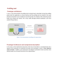
5.2 PSE’S FOR SFM
The Problem Solving Environment (PSE) for Seasonal Forecast Model (SFM) is a webinterface to interact with the Virtual Clusters provided by scientific cloud to run the SFM
application for weather prediction.
Hardware Requirements
Cluster of MPICH2 with Linux OS
A cluster of MPICH2 having Torque as a scheduler
Software Requirements
Apache tomcat Web/Application server for communication
Mysql Database to store information
Torque Scheduler for Linux clusters.
GrADS for Visualization
1. User can access the PSE for SFM Portal by typing the following URL in the browser:
http://Ip Address:8080/pse-sfm
2. User can submit the weather forecasting job by selecting the number of process and can give
the related input file having .ieee extension. Figure 12 shows the Job Submission page of
PSE for SFM.
3. User can monitor the status of the job by selecting the appropriate job-id and after
completion of job user can view the output/error file(s). Figure 13 shows the Job Info page.
33
Figure 11: Login page for PSE for SFM
Figure 12: Job Submission page
34
Figure 13: Job Info page
4. Web- based File Explorer is provided for the user to view the directories and file and to
download the file.
Figure 14: File Browser
5. After completion of job, the flx.**** output file is generated. This file has to be converted
into descriptor file i.e. .ctl file. Using this descriptor file, the user can do visualization and
enter the grads commands in the text area provided, as shown in Figure 15.
35
Figure 15: Visualization
36
LIST OF FIGURES
Figure 1: Cloud computing layers
Figure 2: Cloud computing types
Figure 3: SuMegha Cloud Stack
Figure 4: SuMegha Cloud Architecture
Figure 5: Puttygen - Convert ssh private key to putty compatible format
Figure 6: Putty - uploading ssh private key to login to the remote machine
Figure 7: Login page for Job Submission Portal for Scientific Cloud
Figure 8: Job Submission Page
Figure 9: Job Info Page
Figure 10: Adding users
Figure 11: Login page for PSE for SFM
Figure 12: Job Submission page
Figure 13: Job Info page
Figure 14: File Browser
Figure 15: Visualization
37