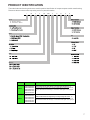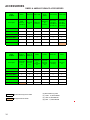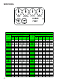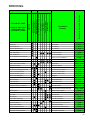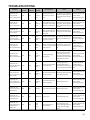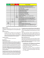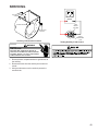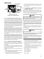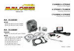
1
Service Instructions Goodman® Brand GMEC96 & Amana® Brand AMEC96 Two Stage Furnace with multi-speed ECM Motor This manual is to be used by qualified, professionally trained HVAC technicians only. Goodman does not assume any responsibility for property damage or personal injury due to improper service procedures or services performed by an unqualified person. The material in this manual does not supercede manufacturers installation and operation instructions. is a registered trademark of Maytag Corporation or its related companies and is used under license to Goodman Company, L.P., Houston, TX, USA. All rights reserved. ® Copyright© 2014 Goodman Company, L.P. RS6612013 August 2014 TABLE OF CONTENTS IMPORTANT INFORMATION ......................... 2 - 6 ACCESSORIES .......................................... 34 - 37 PRODUCT IDENTIFICATION ........................ 7 - 8 SERVICING TABLE OF COnTENTS ................. 38 INSTALLATION CONSIDERATIONS ........... 9 - 26 SERVICING .. .............................................. 39 - 56 SYSTEM OPERATION ...............................27 - 33 MAINTENANCE ............................................57- 58 IMPORTANT INFORMATION Pride and workmanship go into every product to provide our customers with quality products. It is possible, however, that during its lifetime a product may require service. Products should be serviced only by a qualified service technician who is familiar with the safety procedures required in the repair and who is equipped with the proper tools, parts, testing instruments and the appropriate service manual. REVIEW ALL SERVICE INFORMATION IN THE APPROPRIATE SERVICE MANUAL BEFORE BEGINNING REPAIRS. IMPORTANT NOTICES FOR CONSUMERS AND SERVICERS RECOGNIZE SAFETY SYMBOLS, WORDS AND LABELS TO PREVENT THE RISK OF PROPERTY DAMAGE, PERSONAL INJURY, OR DEATH , DO NOT STORE COMBUSTIBLE MATERIALS OR USE GASOLINE OR OTHER FLAMMABLE LIQUIDS OR VAPORS IN THE VICINITY OF THIS APPLIANCE. GOODMAN WILL NOT BE RESPONSIBLE FOR ANY INJURY OR PROPERTY DAMAGE ARISING FROM IMPROPER SERVICE OR SERVICE PROCEDURES . IF YOU INSTALL OR PERFORM SERVICE ON THIS UNIT, YOU ASSUME RESPONSIBILITY FOR ANY PERSONAL INJURY OR PROPERTY DAMAGE WHICH MAY RESULT. MANY JURISDICTIONS REQUIRE A LICENSE TO INSTALL OR SERVICE HEATING AND AIR CONDITIONING EQUIPMENT. WARNING HIGH VOLTAGE DISCONNECT ALL POWER BEFORE SERVICING OR INSTALLING THIS UNIT. MULTIPLE POWER SOURCES MAY BE PRESENT. FAILURE TO DO SO MAY CAUSE PROPERTY DAMAGE, PERSONAL INJURY OR DEATH. 2 IMPORTANT INFORMATION DANGER CARBON MONOXIDE POISONING HAZARD Special warning for installation of furnaces or air handling units in enclosed area such as garages, utility rooms or parking areas. Carbon monoxide producing devices (such as automobile, space heater, gas water heater, etc.) Should not be operated in enclosed areas such as unventilated garages or utility rooms because of the danger of carbon monoxide (CO) poisoning resulting from the exhaust emissions. If a furnace or air handler is installed in an enclosed area and a carbon monoxide producing device is operated therein, there must be adequate direct outside ventilation. Carbon monoxide emissions can be (re)circulated throughout the structure if the furnace or air handler is operating in any mode. CO can cause serious illness including permanent brain damage or death. DANGER RISQUE D'EMPOISONNEMENT AU MONOXYDE DE CARBONE Avertissement special au sujet de l'installation d'appareils de chauffage ou de traitement d'air dans des endroits clos, tets les garages, les locaux d'entretien et les stationnements. Evitez de mettre en marche les appareils produisant du monoxyde de carbone (tels que les automobile, les appareils de chauffage autonome,etc.) dans des endroits non ventilés tels que les d'empoisonnement au monoxyde de carbone. Si vous devez faire fonctionner ces appareils dans un endroit clos, assures-vous qu'il y ait une ventilation directe provenant de l'exterie . Les émissions de monoxyde de carbone peuvent etre recircules dans les endroits clos, si l'appareil de chauffage ou de traitement d'air sont en marche. Le monoxyde de carbone peut causer des maladies graves telles que des dommages permanents au cerveau et meme la mort. PELIGRO RIESGO DE INTOXICACIÓN POR MONÓXIDO DE CARBONO Advertencia especial para la instalación de calentadores ó maneja oras de aire en áreas cerradas como estacionamientos ó cuartos de servicio. Los equipos ó aparatos que producen monóxido de carbono (tal como automóvil, calentador de gas, calentador de agua por medio de gas, etc) no deben ser operados en áreas cerradas debido al riesgo de envenenamiento por monóxido de carbono (CO) que resulta de las emisiones de gases de combustión. Si el equipo ó aparato se opera en dichas áreas, debe existir una adecuada ventilac ón directa al exterior. Las emisiones de monóxido de carbono pueden circular a través del aparato cuando se opera en cualquier modo. El monóxido de carbono puede causar enfermedades severas como daño cerebral permanente ó muerte. 0140M00020-D To locate an authorized servicer, please consult your telephone book or the dealer from whom you purchased this product. For further assistance, please contact: CONSUMER INFORMATION LINE GOODMAN® BRAND PRODUCTS TOLL FREE 1-877-254-4729 (U.S. only) email us at: [email protected] fax us at: (731) 856-1821 (Not a technical assistance line for dealers.) CONSUMER INFORMATION LINE AMANA® BRAND PRODUCTS TOLL FREE 1-877-254-4729 (U.S. only) email us at: [email protected] fax us at: (731) 856-1821 (Not a technical assistance line for dealers.) Outside the U.S., call 1-713-861-2500. (Not a technical assistance line for dealers.) Your telephone company will bill you for the call. 3 IMPORTANT INFORMATION FOR YOUR SAFETY READ BEFORE OPERATING If you do not follow these instructions exactly, a fire or explosion may result causing property damage, personal injury or loss of life. A. This appliance does not have a pilot. It is equipped with an ignition device which automatically lights the burners. Do not try to light the burners by hand. B. BEFORE OPERATING smell around the appliance area for gas. Be sure to smell next to the floor because some gas is heavier than air and will settle on the floor. WHAT TO DO IF YOU SMELL GAS Do not try to light any appliance. Do not touch any electric switch; do not use any telephone in your building. Immediately call your supplier from a neighbor's phone. Follow the gas suppliers instructions. If you cannot reach your gas supplier, call the fire department. C. Use only your hand to move the gas control switch or knob. Never use tools. If the gas control switch or knob will not operate, don't try to repair it, call a qualified service technician. Force or attempted repair may result in a fire or explosion. D. Do not use this appliance if any part has been under water. Immediately call a qualified service technician to inspect the appliance and to replace any part of the control system and any gas control which has been under water. WARNING: Improper alteration, service or maintenance can cause injury or property damage. Refer to the user's information manual provided with this consult a qualified or the gas supplier. This furnace must be instructions and local codes. In the absence of local codes, follow the National Fuel Gas Code, ANSI Z223.1. OPERATING INSTRUCTIONS 1. STOP! Read the safety information above on this label. 2. Set the thermostat to lowest setting. 3. Turn off all electric power to the appliance. 4. This appliance is equipped with an automatic ignition system which automatically lights the burners. Do not try to light the burners by hand. 5. Remove control access panel. 6. Move the gas control switch or knob to "OFF". 7. Wait five (5) minutes to clear out any gas. If you then smell gas, STOP! Follow "B" in the safety information above on this label. If you don't smell gas, go to the next step. 8. Move the gas control switch or knob to "ON". 9. Replace control access panel. 10. Turn on all electric power to the appliance. 11. Set the thermostat to the desired setting. 12. If the appliance will not operate, follow the instructions "To Turn Off Gas To Appliance" and call your service technician or gas supplier. GAS CONTROL SWITCH SHOWN IN "ON" POSITION TO TURN OFF GAS TO APPLIANCE 1. Set the thermostat to its lowest setting. 2. Turn off all electric power to the appliance if service is to be performed. 3. Remove control access panel. 4. Move the gas control switch or knob to "OFF". Do not force. 5. Replace control access panel. For indoor installation. PGB & PGJ For outdoor installation only. WARNING: If not installed, operated and maintained in accordance with the manufacturer's instructions, this product could expose you to substances in fuel combustion which can cause death or serious illness and which are known to the State of California to cause cancer, birth defects or other reproductive harm. This product contains fiberglass insulation. Fiberglass insulation contains a chemical California to cause cancer. FOR YOUR SAFETY Do not store or use gasoline or other flammable vapors and liquids in the vicinity of this or any other appliance. 0140F00001P 4 IMPORTANT INFORMATION CONSIGNES DE SECURITE - LIRE AVANT D'ALLUMER L'APPAREIL INSTRUCTIONS DE SERVICE AVERTISSEMENT: Le non-respect des instructions qui suivent peut ^ entrainer un risque d'incendie ou d'explosion causant des dommages, des blessures ou la mort. A. Cet appareil comporte pas de veilleuse. Il est muni d'un mecanisme qui allume ^ ^ manuellement. automatiquement le bruleur. N'allumez paz le bruleur B. Sentir tout autour de l'appariel AVANT D'ALLUMER afin de deceler toute fuite de gaz. Assurez-vous de sentir tout pres du plancher car certains gaz sont plus lourds que l'air et se deposeront sur le plancher. SI VOUS SENTEZ UNE ODEUR DE GAZ: Ne tentez d'allumer aucun appariel. Ne touchez pas aux interrupteurs electriques; n'utiliser aucun telephone dans l'edifice ou vous vous trouvez. Appelez immediatement votre fournisseur de gaz en utilisant le telephone d'un voisin et suivez les instructions du fournisseur. Appelez les pompiers si vous ne parvenez pas a rejoindre votre fournisseur de gaz. C. N'utiliser que votre main pour pousser ou tourner le commande du gaz. N'utilisez jamais d'outils. Si vous ne parvenez pas a pousser ou a tourner la commande, ne tentez pas de la reparer; appelez un reparateur qualifie. Forcer la commande ou essayer de la ^ reparer peut entrainer un risque d'incendie ou d'explosion. D. N'utilisez pas cet appareil si l'une de ses parties a ete dans l'eau. Si cela se produit, demandez immediatement a un reparateur qualifie d'inspecter l'appareil et de remplacer ^ toute piece du systeme de controle et toute commande de gaz ayant ete dans l'eau. 0140F00002P 1. UN INSTANT! Lisez d'abord les consignes de securite ci-dessus. 2. Reglez le thermostat a son point le plus bas. 3. Coupez l'alimentation electrique de l'appareil. 4. Cet appareil est muni d'un mecanisme qui ^ allume automatiquement le bruleur. Ne tentez ^ pas d'allumer le bruleur manuellement. 5. Retirez le panneau d'acces de la commande. 6. Mettez la commande de gaz a la position ^ ARRET ("OFF"). 7. Attendez cinq (5) minutes afin de permettre a ^ tout gaz present d'etre evacue. Si vous sentez ^ une odeur de gaz a ce moment, ARRETEZ! et suivez les consignes de securite donnees au paragraphe B ci-dessus. Si vous ne sentez pas de gaz, passez a l'etape suivante. 8. Mettez la commande de gaz a la position MARCHE ("ON"). 9. Remettez la panneau d'acces de la commande en place. 10. Retablissez l'alimenation electrique de l'appareil. 11. Reglez le thermostat a le temperature desiree. 12. Si l'appareil ne fonctionne pas, suivez les ^ instructions intitulees "Arret du gaz" et appelez un reparateur qualifie ou votre fournisseur de gaz. ^ Commande de gaz en position "MARCHE" ARRET DU GAZ 1. 2. 3. 4. 5. Reglez le thermostat a son point le plus bas. Coupez l'alimentation electrique de l'appareil si vous devez effectuer un entretien. Retirez le panneau d'acces de la commande. ^ Mettez la commande de gaz a la position ARRET ("OFF"). Remettez le panneau d'acces de la commande en place. 5 IMPORTANT INFORMATION ROBINET A GAZ MANUEL, EN POS "ON/MARCHE" GAS INLET ARRIVEE DU GAZ MANUAL GAS LEVER SHOWN IN "ON" POS 6 PRODUCT IDENTIFICATION The model and manufacturing number are used for positive identification of component parts used in manufacturing. Please use these numbers when requesting service or parts information. * 1 M 2 E 3 C 4 96 5,6 060 7,8,9 3 10 B 11 N 12 A 13 A 14 Brand AA - -Amanafi Brand Amana® Brand GG - -Goodmanfi Brand Goodman® Brand Motor NOx AFUE MBTU/h MODEL # MFG. # DESCRIPTION AMEC96 AMEC060302BNAA AMEC960402BNAA AMEC060603BNAA AMEC960803BNAA AMEC961004CNAA AMEC961205DNAA Amana® Brand 96% Two Stage Heating / Two Stage Cooling Gas Furnace, Up flow/Horizontal Left and Right, 34.5" tall, Induced Draft, Nidec multi-speed ECM motor. Stainless Steel tubular heat exchanger. 115 volt silicon nitride igniter. Left or right gas ent GMEC96 GMEC060302BNAA GMEC960402BNAA GMEC060603BNAA GMEC960803BNAA GMEC961004CNAA GMEC961205DNAA Goodman ® Brand 96% Two Stage Heating / Two Stage Cooling Gas Furnace, Up flow/Horizontal Left and Right, 34.5" tall, Induced Draft, Nidec multi-speed ECM motor. Aluminized Steel tubular heat exchanger. 115 volt silicon nitride igniter. Left or right gas 7 PRODUCT IDENTIFICATION MODEL # AFE18-60A AMU1620 AMU1625 AMU2020 AMU2025 GMU1620 GMU1625 GMU2020 GMU2025 ASAS-10 ASAS-11 ASAS-12 ASAS-18 8 MFG # DESCRIPTION N/A Fossil Fuel Kit. The AFE18-60A control is designed for use where the indoor coil is located above/downstream of a gas or fossil fuel furnace when used with a heat pump. It will operate with single and two stage heat pumps and single and two stage furnaces. The AFE18-60A control will turn the heat pump unit off when the furnace is turned on. An antishort cycle feature initiates a 3 minute timed off delay when the compressor goes off. P1251305F P1251306F P1251307F P1251308F N/A Media Air Cleaner. The Amana (AMU*) and Goodman (GMU*) Media Air Cleaner is a high efficiency air filtration device designed to remove dirt, dust, pollen and other microscopic particles from the air passing through it. Flexible performance range up to 2,000 CFM capacity. The air cleaner should be installed in the system so that all the system air is circulated through the air cleaner. The air cleaner will only remove the airborne contaminants delivered to it. Maximum performance is obtained when the system blower is set for continuous operation. Carbon filters (optional) are available. P1251301F P1251302F P1251303F P1251304F Electronic Air Cleaner. The High-Efficiency Electronic Air Cleaner is designed to remove air contaminants down to .01 microns. Carbon filters (optional) remove odors. Dual indicator lights show unit operation at a glance. Electronic proving switch cycles the air cleaner On/Off with the system fan. Durable powder-coat paint finish resists corrosion. Concentric Vent Kit. For use with Amana® Brand high efficiency furnace models. This kit is designed to allow terminations of a direct vent furnace to be "concentrically" vented through a wall or roof. This kit allows a single penetration to support terminations for both the vent/flue and the combustion air intake pipe. The DCVK-20 (2") and DCVK-30 (3") kits are certified for models listed above. See specification sheets on future models for use of the vent kit. DCVK-20 P1254001F DCVK-30 P1254002F 0170K00000S N/A Side Wall Only Concentric Vent Kit. For use with high efficiency furnace models. This kit is to be used with 2" - 3" vent systems. The vent kit must terminate outside the structure. This kit is NOT intended for use with single pipe (indirect vent) installations. 0170K00001S N/A Side Wall Only Concentric Vent Kit. For use with high efficiency 90% furnace models. This kit is to be used with 2" only vent systems. The vent kit must terminate outside the structure. This kit is NOT intended for use with single pipe (indirect vent) installations. EFR02 P1221001 P1221002F External Filter Rack Kit. This kit is intended to provide a location, external to the furnace casing, for installation of a permanent filter. The rack is mounted over the indoor air blower compartment area of either side panel, and provide filter retention as well as a location for attaching return air ductwork. LPLP03 N/A LP Gas Low Pressure Kit. Designed for application on Goodman® and Amana® Brand's 80% and 90% single-stage and two-stage gas fired furnace products installed on LP gas listed in this manual. This kit includes harness adaptors to work with White-Rodgers single & two stage gas valves,Honeywell single and two-stage gas valves, as well as modulating gas valves. RF000142 N/A Vent Drain Coupling. For use when the furnaces is installed in horizontal left position and the internal elbow is removed. INSTALLATION CONSIDERATIONS Introduction This is a Category lV furnace. This furnace uses a pressurized venting system and must be installed per National and local codes requirements and the installation manual that was shipped with the furnace. The *MEC96 34.5" furnace is one of the products in our newly redesigned line of shorter chassis furnaces. It is available in the following sizes and suitable for up flow / horizontal installation. *MEC960302BNAA *MEC960402BNAA *MEC960603BNAA *MEC960803BNAA *MEC961004CNAA *MEC961205DNAA Safety Please adhere to the following warnings and cautions when installing, adjusting, altering, servicing, or operating the furnace. WARNING TO PREVENT PERSONAL INJURY OR DEATH DUE TO IMPROPER INSTALLATION, ADJUSTMENT, ALTERATION, SERVICE OR MAINTENANCE, REFER TO THIS MANUAL. FOR ADDITIONAL ASSISTANCE OR INFORMATION, CONSULT A QUALIFIED INSTALLER, SERVICE AGENCY OR THE GAS SUPPLIER. WARNING THIS PRODUCT CONTAINS OR PRODUCES A CHEMICAL OR CHEMICALS WHICH MAY CAUSE SERIOUS ILLNESS OR DEATH AND WHICH ARE KNOWN TO THE STATE OF CALIFORNIA TO CAUSE CANCER, BIRTH DEFECTS OR OTHER REPRODUCTIVE HARM. WARNING TO PREVENT POSSIBLE PROPERTY DAMAGE, PERSONAL INJURY OR DEATH DUE TO ELECTRICAL SHOCK, THE FURNACE MUST BE LOCATED TO PROTECT THE ELECTRICAL COMPONENTS FROM WATER. Charge (ESD) Precautions NOTE: Discharge body’s static electricity before touching unit. An electrostatic discharge can adversely affect electrical components. Use the following precautions during furnace installation and servicing to protect the integrated control module from damage. By putting the furnace, the control, and the person at the same electrostatic potential, these steps will help avoid exposing the integrated control module to electrostatic discharge. This procedure is applicable to both installed and uninstalled (ungrounded) furnaces. 1. Disconnect all power to the furnace. Do not touch the integrated control module or any wire connected to the control prior to discharging your body’s electrostatic charge to ground. 2. Firmly touch a clean, unpainted, metal surface of the furnace near the control. Any tools held in a person’s hand during grounding will be discharged. 3. Service integrated control module or connecting wiring following the discharge process in Step 2. Use caution not to recharge your body with static electricity; (i.e., do not move or shuffle your feet, do not touch ungrounded objects, etc.). If you come in contact with an ungrounded object, repeat Step 2 before touching control or wires. 4. Discharge any static electricity from your body to ground before removing a new control from its container. Follow Steps 1 through 3 if installing the control on a furnace. Return any old or new controls to their containers before touching any ungrounded object. Product Application This product is designed for use as a residential home gas furnace. It is not designed or certified for use in mobile home, trailer, or recreational vehicle applications. This furnace can be used in the following non-industrial commercial applications: Schools, Office buildings, Churches, Retail stores, Nursing homes, Hotels/motels, Common or office areas. In such applications, the furnace must be installed with the installation instructions. The *MEC96 furnaces are ETL certified appliances and are appropriate for use with natural or propane gas. (NOTE: If using propane gas, a propane conversion kit is required). *MEC96 furnaces are dual certified. Dual certification means that the combustion air inlet pipe is optional and the furnace can be vented as a: Non-direct vent (single pipe) central forced air furnace in which combustion air is taken from the installation area or from air ducted from the outside or, Direct vent (dual pipe) central forced air furnace in which all combustion air supplied directly to the furnace burners through a special air intake system outlined in this manual and the installation instructions. To ensure proper installation, operation and servicing, thoroughly read the installation and service manuals for specifics pertaining to the installation, servicing and application of this product. WARNING POSSIBLE PROPERTY DAMAGE, PERSONAL INJURY OR DEATH DUE TO FIRE, EXPLOSION, SMOKE, SOOT, CONDENSTAION, ELECTRICAL SHOCK OR CARBON MONOXIDE MAY RESULT FROM IMPROPER INSTALLATION, REPAIR, OPERATION, OR MAINTENANCE OF THIS PRODUCT. 9 INSTALLATION CONSIDERATIONS WARNING TO PREVENT PROPERTY DAMAGE, PERSONAL INJURY OR DEATH DUE TO FIRE, DO NOT INSTALL THIS FURNACE IN A MOBILE HOME, TRAILER, OR RECREATIONAL VEHICLE. To ensure proper furnace operation, install, operate, maintain and service the furnace in accordance with the installation, operation and service instructions, all local building codes and ordinances. In their absence, follow the latest edition of the National Fuel Gas Code (NFPA 54/ANSI Z223.1), and/or CAN/CGA B149 Installation Codes, local plumbing or waste water codes, and other applicable codes. A copy of the National Fuel Gas Code (NFPA 54/ANSI Z223.1) can be obtained from any of the following: American National Standards Institute 1430 Broadway New York, NY 10018 National Fire Protection Association 1 Batterymarch Park Quincy, MA 02269 CSA International 8501 East Pleasant Valley Cleveland, OH 44131 A copy of the CAN/CGA B149 Installation Codes can be obtained from: CSA International 178 Rexdale Boulevard Etobicoke, Ontario, Canada M9W, 1R3 The rated heating capacity of the furnace should be greater than or equal to the total heat loss of the area to be heated. The total heat loss should be calculated by an approved method or in accordance with “ASHRAE Guide” or “Manual J-Load Calculations” published by the Air Conditioning Contractors of America. Location Requirements and Considerations WARNING TO PREVENT POSSIBLE EQUIPMENT DAMAGE, PROPERTY DAMAGE, PERSONAL INJURY OR DEATH, THE FOLLOWING BULLET POINTS MUST BE OBSERVED WHEN INSTALLING THE UNIT. Follow the instructions listed below when selecting a furnace location. Refer also to the guidelines provided in the Combustion and Ventilation Air Requirements section in this manual or the installation instructions for details. • Centrally locate the furnace with respect to the proposed or existing air distribution system. • Ensure the temperature of the return air entering the furnace is between 55°F and 100°F when the furnace is heating. 10 • If the furnace is installed in an application where the typical operating sound level of a furnace is deemed objectionable, an optional sound reduction kit is available. Consult your local distributor for more details. • Provide provisions for venting combustion products outdoors through a proper venting system. Special consideration should be given to vent/flue pipe routing and combustion air intake pipe when applicable. 90% Furnaces: Refer to the Vent/Flue Pipe and Combustion Air Pipe -Termination Locations section in this manual or the installation instructions for appropriate termination locations. Also for 90% furnaces, refer to the Vent/Flue Pipe and Combustion Air Pipe -Termination Locations section in this manual or the installation instructions to determine if the piping system from furnace to termination can be accomplished within the guidelines given. NOTE: The length of flue and/or combustion air piping can be a limiting factor in the location of the furnace. • Locate the 90% furnace so that the condensate can be piped at a downward slope away from the furnace to the drain. Do not locate the furnace or its condensate drainage system in any area subject to below freezing temperatures without proper freeze protection. Refer to the Condensate Drain Lines and Trap section in this manual or the installation instructions for further details. • Set the 90% furnace on a level floor to enable proper condensate drainage. If the floor becomes wet or damp at times, place the furnace above the floor on a concrete base sized approximately 1-1/2" larger than the base of the furnace. Refer to the Horizontal Applications and Considerations section in this manual or the installation instructions for leveling of horizontal furnaces. • Ensure upflow or horizontal furnaces are not installed directly on carpeting, or any other combustible material. The only combustible material allowed is wood. • Exposure to contaminated combustion air will result in safety and performance-related problems. Do not install the furnace where the combustion air is exposed to the following substances: chlorinated waxes or cleaners chlorine-based swimming pool chemicals water softening chemicals deicing salts or chemicals carbon tetrachloride halogen type refrigerants INSTALLATION CONSIDERATIONS • • • cleaning solutions (such as perchloroethylene) printing inks paint removers varnishes hydrochloric acid cements and glues antistatic fabric softeners for clothes dryers and masonry acid washing materials Isolate a non-direct vent furnace if it is installed near an area frequently contaminated by any of the above substances. This protects the non-direct vent furnace from airborne contaminants. To ensure that the enclosed non-direct vent furnace has an adequate supply of combustion air, vent from a nearby uncontaminated room or from outdoors. Refer to the Combustion and Ventilation Air Requirements section in this manual or the installation instructions for details. If the furnace is used in connection with a cooling unit, install the furnace upstream or in parallel with the cooling unit coil. Premature heat exchanger failure will result if the cooling unit coil is placed in the return air of the furnace. If the furnace is installed in a residential garage, position the furnace so that the burners and ignition source are located not less than 18 inches (457 mm) above the floor. Protect the furnace from physical damage by vehicles. • If the furnace is installed horizontally, the furnace access doors must be vertical so that the burners fire horizontally into the heat exchanger. Do not install the unit with the access doors on the “up/top” or “down/ bottom” side of the furnace. Clearances and Accessibility Installations must adhere to the clearances to combustible materials to which this furnace has been design certified. The minimum clearance information for this furnace is provided on the unit’s clearance label. These clearances must be permanently maintained. Refer to Specification Sheet for minimum clearances to combustible materials. Clearances must also accommodate an installation’s gas, electrical, and drain trap and drain line connections. If the alternate combustion air intake or vent/flue connections are used on a 90% furnace, additional clearances must be provided to accommodate these connections. Refer to Vent Flue Pipe and Combustion Air Pipe section in this manual or the installation instructions for details. NOTE: In addition to the required clearances to combustible materials, a minimum of 24 inches service clearance must be available in front of the unit. A furnace installed in a confined space (i.e., a closet or utility room) must have two ventilation openings with a total minimum free area of 0.25 square inches per 1,000 BTU/hr of furnace input rating. One of the ventilation openings must be within 12 inches of the top; the other opening must be within 12 inches of the bottom of the confined space. In a typical construction, the clearance between the door and door frame is usually adequate to satisfy this ventilation requirement. MINIMUM CLEARANCES TO COMBUSTIBLE MATERIALS POSITION Upflow Horizontal SIDES 0" 6" REAR 0" 0" FRONT 1" 1" BOTTOM C C FLUE 0" 0" TOP 1" 4" • C = if placed on combustible floor, the floor MUST be wood ONLY. • For servicing or cleaning, a 24" front clearance is recommended. • Unit connections (electrical, flue, and drain) may necessitate greater clearances than the minimum clearances listed above • In all case, accessibility clearance must take precedence over from the enclosure where accessitility clearances are greater. • Approved for line contact in the horizontal position. 11 INSTALLATION CONSIDERATIONS Furnace Suspension If suspending the furnace from rafters or joist, use 3/8" threaded rod and 2”x2”x1/8” angle iron as shown in the following figure. If the furnace is installed in a crawl space it must also be suspended from the floor joist or supported by a concrete pad. Never install the furnace on the ground or allow it to be exposed to water. The length of rod will depend on the application and the clearances necessary. PROVIDE 8" MINIMUM CLEARANCE BETWEEN CENTER ROD AND FURNACE CABINET TO ALLOW FOR CIRCULATOR BLOWER REMOVAL. 3/8" DIAMETER ALTERNATE THREADED ROD GAS PIPING ASSURE FURNACE IS LEVEL FROM END TO END. ON 90% FURNACES MAKE SURE (6 PLACES) THE UNIT HAS A SLIGHT FORWARD TILT WITH THE FRONT OF THE FURNACE 0"-3/4" HOLD DOWN BELOW THE BACK OF THE FURNACE. NUTS SUPPORT NUTS f. After it has been determined that each appliance connected to the venting system properly vents when tested as outlined above, return doors, windows, exhaust fans, fireplace dampers and any other gas burning appliance to their previous conditions of use; g. If improper venting is observed during any of the above tests, the common venting system must be corrected. Corrections must be in accordance with the latest edition of the National Fuel Gas Code NFPA 54/ANSI Z223.1 and/or CSA B149 Installation Codes. If resizing is required on any portion of the venting system, use the appropriate table in Appendix G in the latest edition of the National Fuel Gas Code ANSI Z223.1 and/or CSA B149 Installation Codes. Thermostat Requirements A two stage heat/cool thermostat is recommended. A single stage heating thermostat may be used. It is recommended that a high quality thermostat with a "C" terminal is used to operate the furnace. CONDENSATE DRAIN GAS PIPING 2"X2"X1/8" ANGLE IRON (3 PLACES) TILT OUTWARD TO ALLOW FOR POSITION AS CLOSE AS POSSIBLE DOOR AND CIRCULATOR BLOWER TO BLOWER DECK TO ALLOW FOR REMOVAL. CIRCULATOR BLOWER REMOVAL. 90% Suspended Furnace Shown Thermostat Location In an area having good air circulation, locate the thermostat about five feet high on a vibration-free inside wall. Do not install the thermostat where it may be influenced by any of the following: • EXISTING FURNACE REMOVAL NOTE: When an existing furnace is removed from a venting system serving other appliances, the venting system may be too large to properly vent the remaining attached appliances. The following vent testing procedure is reproduced from the American National Standard/National Standard of Canada for Gas-Fired Central Furnaces ANSI Z21.47, latest edition, CSA-2.3b, latest edition Section 1.23.1. The following steps shall be followed with each appliance connected to the venting system placed in operation, while any other appliances connected to the venting system are not in operation: a. Seal any unused openings in the venting system; b. Inspect the venting system for proper size and horizontal pitch, as required by the National Fuel Gas Code, ANSI Z223.1 or the CSA B149 Installation Codes and these instructions. Determine that there is no blockage or restriction, leakage, corrosion and other deficiencies which could cause an unsafe condition; c. In so far as practical, close all building doors and windows and all doors between the space in which the appliance(s) connected to the venting system are located and other spaces of the building. Turn on clothes dryers and any appliance not connected to the venting system. Turn on any exhaust fans, such as range hoods and bathroom exhausts, so they shall operate at maximum speed. Do not operate a summer exhaust fan. Close fireplace dampers; d. Follow the lighting instructions. Place the appliance being inspected in operation. Adjust thermostat so appliance shall operate continuously; e. Test for draft hood equipped spillage at the draft hood relief opening after 5 minutes of main burner operation. Use the flame of a match or candle; 12 • • • • • • Drafts, or dead spots behind doors, in corners, or under cabinets. Hot or cold air from registers. Radiant heat from the sun. Light fixtures or other appliances. Radiant heat from a fireplace. Concealed hot or cold water pipes, or chimneys. Unconditioned areas behind the thermostat and dehumidistat, such as an outside wall. COMBUSTION AND VENTILATION AIR REQUIREMENTS WARNING POSSIBLE PROPERTY DAMAGE, PERSONAL INJURY OR DEATH MAY OCCUR IF THE FURNACE IS NOT PROVIDED WITH ENOUGH FRESH AIR FOR PROPER COMBUSTION AND VENTILATION OF FLUE GASES. MOST HOMES REQUIRE OUTSIDE AIR BE SUPPLIED TO THE FURNACE AREA. Improved construction and additional insulation in buildings have reduced heat loss by reducing air infiltration and escape around doors and windows. These changes have helped in reducing heating/cooling costs but have created a problem supplying combustion and ventilation air for gas fired and other fuel burning appliances. Appliances that pull air out of the house (clothes dryers, exhaust fans, fireplaces, etc.) increase the problem by starving appliances for air. When the furnace is installed as a direct ven (2-pipe) furnace, no special provisions for air for combustion are required. However, if this furnace is to be installed in the same INSTALLATION CONSIDERATIONS space with other gas appliances, such as a water heater, ensure there is an adequate supply of combustion and ventilation air for the other appliances. Refer to the latest edition of the National Fuel Gas Code NFPA 54/ANSI Z223.1 (Section 9.3), or CAN/CGA B149 Installation Codes (Sections 7.2, 7.3, or 7.4), or applicable provisions of the local building codes for determining the combustion air requirements for the appliances. Most homes will require outside air be supplied to the furnace area by means of ventilation grilles or ducts connecting directly to the outdoors or spaces open to the outdoors such as attics or crawl spaces. The following information on air for combustion and ventilation is reproduced from the National Fuel Gas Code NFPA 54/ANSI Z223.1 Section 9.3. 9.3* Air for Combustion and Ventilation. 9.3.1 General. 9.3.1.1 Air for combustion, ventilation, and dilution of flue gases for appliances installed in buildings shall be obtained by application of one of the methods covered in 9.3.2 through 9.3.6. Where the requirements of 9.3.2 are not met, outdoor air shall be introduced in accordance with methods covered in 9.3.3 through 9.3.6. Exception No. 1: This provision shall not apply to direct vent appliances. 9.3.1.2 Appliances of other than natural draft design and other than Category 1 vented appliances shall be provided with combustion, ventilation, and dilution air in accordance with the appliance manufacturer’s instructions. 9.3.1.3 Appliances shall be located so as not to interfere with proper circulation of combustion, ventilation, and dilution air. Required Volume other 21 ft3 > ________ ACH ( (2) For fan-assisted appliances, calculate using the following equation: I fan 15 ft3 Required Volume fan > ________ _________ ACH 1000 Btu/hr where: I other = all appliances other than fan-assisted input in Btu per hour fan = fan-assisted appliances input in Btu per hour ACH = air change per hour (percent of volume of space exchanged per hour, expressed as a decimal) I (3) For purposes of this calculation, an infiltration rate greater than 0.60 ACH shall not be used in the equations in 9.3.2.2(1) and 9.3.2.2(2). 9.3.2.3 Indoor Opening Size and Location. Openings used to connect indoor spaces shall be sized and located in accordance with the following: (1)*Combining spaces on the same story. Each opening shall have a minimum free area of 1 in.2/1000Btu/hr (2200 mm2/kW) of the total input rating of all appliances in the space but not less than 100 in.2 (0.60m2). One opening shall commence within 12 in. (300 mm) of the top, and one opening shall commence within 12 in. (300 mm) of the bottom, of the enclosure [see Figure A.9.3.2.3(1)]. The minimum dimension of air openings shall be not less than 3 in. (80 mm). Chimney or Gas Vent NOTE: Each opening must have a free area of not less than one square inch per 1000 BTU of the total input rating of all equipment in the enclosure, but not less than 100 square inches. Opening Furnace 9.3.2 Indoor Combustion Air. The required volume of indoor air shall be determined in accordance with the method in 9.3.2.1 or 9.3.2.2 except that where the air infiltration rate is known to be less than 0.40 ACH, the method in 9.3.2.2 shall be used. The total required volume shall be the sum of the required volume calculated for all appliances located within the space. Rooms communicating directly with the space in which the appliances are installed through openings not furnished with doors, and through combustion air openings sized and located in accordance with 9.3.2.3, are considered a part of the required volume. 9.3.2.1* Standard Method. The minimum required volume shall be 50 ft 3 per 1,000/Btu/hour (4.8m3/kW). 9.3.2.2* Known Air Infiltration Rate Method. Where the air infiltration rate of a structure is known, the minimum required volume shall be determined as follows: ) ( 9.3.1.4 Where used, a draft hood or a barometric draft regulator shall be installed in the same room or enclosure as the appliance served so as to prevent any difference in pressure between the hood or regulator and the combustion air supply. 9.3.1.5 Makeup air requirements for the operation of exhaust fans, kitchen ventilation systems, clothes dryers, and fireplaces shall be considered in determining the adequacy of a space to provide combustion air requirements. ) I other _________ 1000 Btu/hr Water Heater Opening Figure A.9.2.3.3.(1) All Combustion Air from Adjacent Indoor Spaces through Indoor Combustion Air Openings. (2) Combining spaces in different stories. The volumes of spaces in different stories shall be considered as communicating spaces where such spaces are connected by one or more openings in doors or floors having a total minimum free area of 2 in.2/1000 Btu/hr (4400 mm2/kW) of total input rating of all appliances. 9.3.3 Outdoor Combustion Air. Outdoor combustion air shall be provided through opening(s) to the outdoors in accordance with the methods in 9.3.3.1 or 9.3.3.2. The minimum dimension of air openings shall not be less than 3 in. (80 mm). (1) For appliances other than fan-assisted, calculate using the following equation: 13 INSTALLATION CONSIDERATIONS 9.3.3.1 Two Permanent Openings Method. Two permanent openings, one commencing within 12 in. (300 mm) of the top and one commencing within 12 in. (300 mm) of the bottom, of the enclosure shall be provided. The openings shall communicate directly, or by ducts, with the outdoors or spaces that freely communicate with the outdoors, as follows: Chimney or Gas Vent Outlet air duct (1)*Where directly communicating with the outdoors or where communicating to the outdoors through vertical ducts, each opening shall have a minimum free area of 1 in.2/4000 Btu/hr (550 min2/kW) of total input rating of all appliances in the enclosure. [See Figure A.9.3.3.1(1)(a) and Figure A.9.3.3.1(1)(b).] Chimney or Gas Vent Ventilation louvers (each end of attic) NOTE: The inlet and outlet air openings must each have a free area of not less than one square inch per 4000 BTU of the total input rating of all equipment in the enclosure. Outlet Air Water Heater Furnace Inlet Air Alternate air inlet Ventilation louvers for unheated crawl space Figure A.9.3.3.1(1)(a) All Combustion Air From Outdoors Inlet Air from Ventilated Crawl Space and Outlet Air to Ventilated Attic. Furnace NOTE: The air duct openings must have a free area of not less than one square inch per 2000 BTU of the total input rating of all equipment in the enclosure*. Water Heater Inlet air duct Figure A.9.3.3.1(2) All Combustion Air From Outdoors through Horizontal Ducts. 9.3.3.2* One Permanent Opening Method. One permanent openings, commencing within 12 in. (300 mm) of the top of the enclosure, shall be provided. The appliance shall have clearances of at least 1 in. (25 mm) from the sides and back and 6 in. (150 mm) from the front of the appliance. The opening shall directly communicate with the outdoors or shall communicate through a vertical or horizontal duct to the outdoors or spaces that freely communicate with the outdoors (see Figure A.9.3.3.2) and shall have a minimum free area of the following: (1) 1 in.2/3000 Btu/hr (700 mm2 per kW) of the total input rating of all appliances located in the enclosure, and (2) Not less than the sum of the areas of all vent connectors in the space. NOTE: The single opening must have a free area of not less than one square inch per 3000 BTU of the total input rating of all equipment in the enclosure, but not less than the sum of the areas of all vent connectors in the confined space. Chimney or Gas Vent Opening Chimney or Gas Vent Ventilation louvers (each end of attic) NOTE: The inlet and outlet air openings must each have a free area of not less than one square inch per 4000 BTU of the total input rating of all equipment in the enclosure. Furnace Water Heater Alternate Opening Location Outlet Air Furnace Water Heater Inlet air duct [ends 1 ft (300 mm) above floor] Figure A.9.3.3.2 All Combustion Air From Outdoors through Single Combustion Air Opening. 9.3.4 Combination Indoor and Outdoor Combustion Air. The use of a combination of indoor and outdoor combustion air shall be in accordance with (1) through (3) (see example calculation in Annex J]: Figure A.9.3.3.1(1)(b) All Combustion Air From Outdoors through Ventilated Attic. (2)*Where communicating with the outdoors through horizontal ducts, each opening shall have a minimum free area of 1 in.2/2000 Btu/hr (1100 min2/kW) of total input rating of all appliances in the enclosure. [See Figure A.9.3.3.1(2).] 14 (1) Indoor Openings: Where used, openings connecting the interior spaces shall comply with 9.3.2.3. (2) Outdoor Opening(s) Location. Outdoor opening(s) shall be located in accordance with 9.3.3. (3) Outdoor Opening(s) Size. The outdoor opening(s) size shall be calculated in accordance with the following: (a) The ratio of the interior spaces shall be the available volume of all communicating spaces divided by the required volume. (b) The outdoor size reduction factor shall be 1 minus the ratio of interior spaces. INSTALLATION CONSIDERATIONS (c) The minimum size of outdoor opening(s) shall be the full size of outdoor opening(s) calculated in accordance with 9.3.3, multiplied by the reduction factor. The minimum dimension of air openings shall not be less than 3 in. (80 mm). 9.3.5 Engineered Installations. Engineered combustion air installations shall provide an adequate supply of combustion, ventilation, and dilution air and shall be approved by the authority having jurisdiction. 9.3.6 Mechanical Combustion Air Supply. Where all combustion air is provided by a mechanical air supply system, the combustion air shall be supplied form outdoors at the minimum rate of 0.35 ft3/min per 1000 Btu/hr (0.034 m3/min per kW) for all appliances located within the space. 9.3.6.1 Where exhaust fans are installed, additional air shall be provided to replace the exhausted air. 9.3.6.2 Each of the appliances served shall be interlocked to the mechanical air supply system to prevent main burner operation where the mechanical air supply system is not in operation. 9.3.6.3 Where combustion air is provided by the building’s mechanical ventilation system, the system shall provide the specified combustion air rate in addition to the required ventilation air. 9.3.7 Louvers, Grilles, and Screens. 9.3.7.1 Louvers and Grilles. The required size of openings for combustion, ventilation, and dilution air shall be based on the net free area of each opening. Where the free area through a design of louver or grille or screen is known, it shall be used in calculating the size opening required to provide the free area specified. Where the louver and grille design and free area are not known, it shall be assumed that wood louvers will have 25 percent free area, and metal louvers and grilles will have 75 percent free area. Nonmotorized louvers and grilles shall be fixed in the open position. 9.3.7.2 Minimum Scree Mesh Size. Screens shall not be smaller than 1/4 in. mesh. 9.3.7.3 Motorized Louvers. Motorized louvers shall be interlocked with the appliance so they are proven in the full open position prior to main burner ignition and during main burner operation. Means shall be provided to prevent the main burner form igniting should the louver fail to open during burner startup and to shut down the main burner if the louvers close during burner operation. 9.3.8 Combustion Air Ducts. Combustion air ducts shall comply with 9.3.8.1 through 9.3.8.8. 9.3.8.1 Ducts shall be constructed of galvanized steel or a material having equivalent corrosion resistance, strength, and rigidity. 9.3.8.3 Ducts shall serve a single space. 9.3.8.4 Ducts shall not serve both upper and lower combustion air openings where both such openings are used. The separation between ducts servicing upper and lower combustion air openings shall be maintained to the source of combustion air. 9.3.8.5 Ducts shall not be screened where terminating in an attic space. 9.3.8.6 Horizontal upper combustion air ducts shall not slope downward toward the source of combustion air. 9.3.8.7 The remaining space surrounding a chimney liner, gas vent, special gas vent, or plastic piping installed within a masonry, metal, or factory built chimney shall not be used to supply combustion air. Exception: Direct vent appliances designed for installation in a solid fuel-burning fireplace where installed in accordance with the manufacture’s installation instructions. 9.3.8.8 Combustion air intake openings located on the exterior of the building shall have the lowest side of the combustion air intake openings located at least 12 in. (300 mm) vertically from the adjoining grade level. Horizontal Applications and Considerations Horizontal applications, in particular, may dictate many of the installation’s specifics such as airflow direction, ductwork connections, flue and/or combustion air pipe connections, etc. The basic application of this furnace as a horizontal furnace differs only slightly from an upright installation. Horizontal Installations 1. Horizontal installations require 5.5" under the furnace to accommodate the drain trap. 2. Horizontal furnaces must be installed with ¾” slope from back to front to permit condensate flow towards the front of the furnace. When installing a *MEC96 horizontally with the left side down, there are two options for connecting the vent pipe to the furnace. 1. Venting may be connected to the furnace vent pipe fitting on the original top (now the end) of the furnace 2. The internal vent pipe and elbow may be removed from the furnace to permit the vent to exit the top (original side) of the furnace. If this option is used, an RF000142 Vent-Drain coupling must be used to keep condensate from collecting in the inducer assembly Refer to the following instructions and illustration. Exception: Within dwellings units, unobstructed stud and joist spaces shall not be prohibited from conveying combustion air, provided that not more than one fireblock is removed. 9.3.8.2 Ducts shall terminate in an unobstructed space, allowing free movement of combustion air to the appliances. 15 INSTALLATION CONSIDERATIONS Insert flange. Cut 2 ½” long. RF000142 Leveling Leveling ensures proper condensate drainage from the heat exchanger and induced draft blower. For proper flue pipe drainage, the furnace must be level lengthwise from end to end. The furnace should also be level from back to front or have a slight tilt with the access doors downhill (approximately 3/4") from the back panel. The slight tilt allows the heat exchanger condensate, generated in the recuperator coil, to flow forward to the recuperator coil front cover. AIR DISCHARGE Side Return Duct Connection Side Return Duct Connection CUT HERE Bottom Return Duct Connection UPFLOW UPRIGHT Vent/Flue Pipe Cuts 1. Remove screws from the vent flange. 2. Remove the internal elbow and vent pipe 3. Cut 2 1/2" from the flange . 4. Remove cabinet plug adjacent to inducer outlet and install an original cabinet vent hole. 5. Install RF000142 coupling on inducer outlet. 6. Install flanged vent section removed in step 2 and secure with clamps. 7. Secure flange to cabinet using screws removed in step1. Drain Trap and Lines In horizontal applications the condensate drain trap is secured to the furnace side panel, suspending it below the furnace. A minimum clearance of 5.5" below the furnace must be provided for the drain trap. Additionally, the appropriate downward piping slope must be maintained from the drain trap to the drain location. Refer to Condensate Drain Trap and Lines section in this manual or the installation instructions for further details. If the drain trap and drain line will be exposed to temperatures near or below freezing, adequate measures must be taken to prevent condensate from freezing. NOTE: The use of insulation and/or heat tape is recommended. Failure to provide proper condensate drainage can result in property damage. 16 Bottom Return Duct Connection UPFLOW HORIZONTAL LEFT AIR DISCHARGE Bottom Return Duct AIR DISCHARGE UPFLOW HORIZONTAL RIGHT AIR DISCHARGE 90% Furnace Recommended Installation Positions Alternate Electrical and Gas Line Connections The furnaces have provisions allowing for electrical and gas line connections through either side panel. In horizontal applications the connections can be made either through the “top” or “bottom” of the furnace. Drain Pan A drain pan must be provided if the furnace is installed above a conditioned area. The drain pan must cover the entire area under the furnace (and air conditioning coil if applicable). INSTALLATION CONSIDERATIONS Freeze Protection If the drain trap and drain line will be exposed to temperatures near or below freezing, adequate measures must be taken to prevent condensate from freezing. NOTE: The use of insulation and/or heat tape is recommended. Failure to provide proper condensate drainage can result in property damage. Propane Gas and/or High Altitude Installations WARNING POSSIBLE PROPERTY DAMAGE, PERSONAL INJURY OR DEATH MAY OCCUR IF THE APPROPRIATE KITS MUST BE APPLIED TO INSURE SAFE AND PROPER FURNACE OPERATION. ALL THE CORRECT CONVERSION KITS ARE NOT INSTALLED. CONVERSIONS MUST BE PERFORMED BY A QUALIFIED INSTALLER OR SERVICE This furnace must not be connected to Type B, BW, or L vent or vent connector, and must not be vented into any portion of a factory built or masonry chimney except when used as a pathway for PVC as described later in this section. Never common vent this appliance with another appliance or use a vent which is used by a solid fuel appliance. It is the responsibility of the installer to follow the manufacturers’ recommendations and to verify that all vent/flue piping and connectors are compatible with furnace flue products. Additionally, it is the responsibility of the installer to ensure that all piping and connections possess adequate structural integrity and support to prevent flue pipe separation, shifting, or sagging during furnace operation. Materials and Joining Methods AGENCY. WARNING This furnace is shipped from the factory configured for natural gas at standard altitude. Propane gas installations require an orifice change to compensate for the energy content difference between natural and propane gas. High altitude installations may require both a pressure switch and an orifice change. These changes are necessary to compensate for the natural reduction in the density of both the gas fuel and the combustion air at higher altitude. Refer to the Accessories Charts in this manual or product Specification Sheet for a tabular listing of appropriate manufacturer’s kits for propane gas and/or high altitude installations. The indicated kits must be used to insure safe and proper furnace operation. All conversions must be performed by a qualified installer, or service agency. VENT/FLUE PIPE AND COMBUSTION AIR PIPE WARNING FAILURE TO FOLLOW THESE INSTRUCTIONS CAN RESULT IN BODILY INJURY OR O N Y )LDEATH. CAREFULLY READ AND FOLLOW ALL INSTRUCTIONS GIVEN IN THIS SECTION. WARNING UPON COMPLETION OF THE FURNACE INSTALLATION, CAREFULLY INSPECT THE ENTIRE FLUE SYSTEM BOTH INSIDE AND OUTSIDE THE FURNACE TO ASSURE IT IS PROPERLY SEALED. LEAKS IN THE FLUE SYSTEM CAN RESULT IN SERIOUS PERSONAL INJURY OR DEATH DUE TO EXPOSURE TO FLUE PRODUCTS, INCLUDING CARBON MONOXIDE. A condensing gas furnace achieves its high level of efficiency by extracting almost all of the heat from the products of combustion and cooling them to the point where condensation takes place. Because of the relatively low flue gas temperature and water condensation requirements, PVC pipe is used as venting material. TO AVOID BODILY INJURY, FIRE O R EXPLO SION, SOLVENT CEMENTS M UST BE KEPT AW AY FROM ALL IGNITION SOURCES (I.E., SPARKS, OPEN FLAM ES, AND EXCESSIVE HEAT) AS THEY ARE COM BUSTIBLE LIQUIDS. A VOID BREATHING CEMENT VAPORS OR CONTACT W ITH SKIN AND/OR EYES. Precautions should be taken to prevent condensate from freezing inside the vent/flue pipe and/or at the vent/flue pipe termination. It is our recommendation that all vent/ flue piping exposed to temperatures below 35°F for extended periods of time should be insulated with 1/2” thick closed cell foam. Also all vent/flue piping exposed outdoors in excess of the terminations shown in this manual (or in unheated areas) should be insulated with 1/2” thick closed cell foam. Inspect piping for leaks prior to installing insulation. The following bullets and diagram describe the restrictions concerning the appropriate location of vent/flue pipe and combustion air intake pipe (when applicable) terminations. Refer to or the installation instructions for specific details on termination construction. • All terminations must be located at least 12 inches above ground level or the anticipated snow level. • Vent terminations must terminate at least 3 feet above any forced air inlet located within 10 feet. NOTE: This provision does not apply to the combustion air intake termination of a direct vent application. • The vent termination of a non-direct vent application must terminate at least 4 feet below, 4 feet horizontally from, or 1 foot above any door, window, or gravity air inlet into any building. • The vent termination of a direct vent application must terminate at least 12 inches from any opening through which flue gases may enter a building (door, window, or gravity air inlet). 17 INSTALLATION CONSIDERATIONS • The vent termination of vent pipe run vertically through a roof must terminate at least 12 inches above the roof line (or the anticipated snow level) and be at least 12 inches from any vertical wall (including any anticipated snow build up). • A vent termination shall not terminate over public walkways or over an area where condensate or vapor could create a nuisance or hazard or could be detrimental to the operation of regulators, relief valves, or other equipment. • The combustion air intake termination of a direct vent application should not terminate in an area which is frequently dusty or dirty. NOTE: In Canada, the B149 Fuel Gas Code takes precedence over the preceding termination restrictions. Vent/Flue Pipe Lengths (Non-Direct Vent) and Diameters Refer to the following tables for applicable length, elbows, and pipe diameter for construction of the vent/flue pipe system of a non-direct vent installation. In addition to the vent/ flue pipe, a single 90° elbow must be secured to the combustion air intake to prevent inadvertent blockage. The tee or elbows used in the vent/flue termination must be included when determining the number of elbows in the piping system. *MEC96 Direct Vent (2 - Pipe) and Non-Direct Vent (1- Pipe) M aximum Allowable Length of Vent/Flue Pipe & Combustion Air Pipe (ft) Unit Input (Btu) OTHER THAN COMBUSTION AIR TERMINATION INTAKE 40,000 NON-DIRECT VENT VENT/FLUE TERMINATION 60,000 NO TERMINATIONS ABOVE WALKWAY 10' 4' 12" 3" 4' 12" GRADE OR HIGHEST ANTICIPATED SNOW LEVEL 12" 12" FORCED AIR INLET DIRECT VENT VENT/FLUE TERMINATION NON-DIRECT VENT VENT/FLUE TERMINATION 90% Furnace Vent Termination Clearances (6) Number of Elbows Pipe Size (4) (in.) 2 or 2 1/2 2 or 2 1/2 (1) (2) (3) (5) 1 2 3 4 5 6 7 8 120 115 110 105 100 95 90 85 95 90 85 80 75 70 65 60 80,000 "B" 2 or 2 1/2 75 70 65 60 55 50 45 40 80,000 "B" 3 200 193 186 179 172 165 158 151 80,000 "C" 2 or 2 1/2 25 20 15 10 5 N/A N/A N/A 80,000 "C" 3 200 193 186 179 172 165 158 151 100,000 2 or 2 1/2 25 20 15 10 5 N/A N/A N/A 100,000 3 200 193 186 179 172 165 158 151 120,000 2 or 2 1/2 45 40 35 30 25 20 15 10 120,000 3 95 90 85 80 75 70 65 60 1) Maximum allowable limits listed on individual lengths for inlet and flue and NOT a combination. 2) Minimum requirement for each vent pipe is five (5) feet in length and one elbow/tee. 3) Tee used in the vent/flue termination must be included when determining the number of elbows in the piping system. 4) 2 1/2” or 3” diameter pipe can be used in place of 2” diameter pipe. 5) Increased Clearance Configurations using (2) 45 deg. Long Sweep elbows should be considered equivalent to one 90 deg. elbow. 6) One 90° elbow should be secured to the combustion air intake connection. 12" MINIMUM WARNING THE RUBBER ELBOW IS NOT DESIGNED TO SUPPORAT A LOAD. WHEN THE VENT/FLUE TEE OR 90° ELBOW TURNED DOWN RUBBER ELBOW IS MOUNTED EXTERNALLY TO THE FURNACE CABINET, EXTREME CARE MUST BE TAKEN TO ADEQUATELY SUPPORT FIELD-SUPPLIED VENT/FLUE PIPING, AS DAMAGE CAN RESULT IN LEAKS CAUSING BODILY INJURY OR DEATH DUE TO EXPOSURE TO FLUE GASES, INCLUDING CARBON MONOXIDE. 12" MINIMUM ABOVE HIGHEST ANTICIPATED SNOW LEVEL 90% Furnace Horizontal Termination (Single Pipe) Above Highest Anticipated Snow Level 18 INSTALLATION CONSIDERATIONS 10”- 24” NOTE: Terminate both pipes in the same pressure zone (same side of roof, no major obstacles between pipes, etc.). 6” MAX TEE (OPTIONAL) COMBUSTION AIR INTAKE (OPTIONAL) 12” MIN HEIGHT DIFFERENCE BETWEEN INTAKE AND VENT *Not required for single pipe installation OF RO 4” MIN 90º OR 45° ELBOW SCREEN (OPTIONAL) E LIN 12" MIN. TO GRADE OR HIGHEST ANTICIPATED SNOW LEVEL INTAKE SCREEN OPTIONAL 9 X. MA ” 6 IN. ”M 3 - Standard Horizontal Terminations (Dual Pipe) 12” MIN TO ROOF OR HIGHEST ANTICIPATED SNOW LEVEL 90° ELBOWS ELBOWS 3” - 24” STRAIGHT 12" MIN. AIR INTAKE SCREEN (OPTIONAL) VENT/FLUE TEE (OPTIONAL) or 45° ELBOW TURNED DOWN or 90° ELBOW TURNED DOWN 12" MIN. ABOVE HIGHEST ANTICIPATED SNOW LEVEL Alternate Horizontal Vent Termination (Dual Pipe) 12" MIN. ABOVE HIGHEST ANTICIPATED SNOW LEVEL 90° ELBOWS Horizontal Termination (Single Pipe) Above Highest Anticipated Snow Level 3”-24” BETWEEN PIPES AIR INTAKE SCREEN (OPTIONAL) 12" MIN. ABOVE HIGHEST ANTICIPATED SNOW LEVEL Combustion Air Intake may also be snorkeled to obtain 12” min ground clearance. Alternate Vent Termination Above Anticipated Snow Level (Dual Pipe) 19 INSTALLATION CONSIDERATIONS VENT/INTAKE TERMINATIONS FOR INSTALLATION OF MULTIPLE DIRECT VENT FURNACES If more than one direct vent furnace is to be installed vertically through a common roof top, maintain the same minimum clearances between the exhaust vent and air intake terminations of adjacent units as with the exhaust vent and air intake terminations of a single unit. If more than one direct vent furnace is to be installed horizontally through a common side wall, maintain the clearances as in the following figure. Always terminate all exhaust vent outlets at the same elevation and always terminate all air intakes at the same elevation. 2. Do NOT terminate over public walkways. Avoid areas where condensate may cause problems such as above planters, patios, or adjacent to windows where steam may cause fogging. 3. The vent termination shall be located at least 4’ horizontally from any electric meter, gas meter, regulator and any relief equipment. These distances apply ONLY to U.S. Installations. 4. The vent termination shall be located at least 3’ above any forced air inlet located within 10’; and at least 10’ from a combustion air intake of another appliance, except another direct vent furnace intake. 5. In Canada, the Canadian Fuel Gas Code takes precedence over the preceding termination instructions. 3" or 4" Diameter SDR-26 Pipe 2 or 2 1/2" Diameter SDR-26 Pipe 3” - 24” 12” MIN SEPARATION 3” MIN 2" or 3" Diameter Y Concentric Fitting OPTIONAL INTAKE SCREENS These kits are for vertical or horizontal termination of the combustion air inlet and the exhaust vent pipes on Category IV gas-fired condensing furnaces. The DCVK-30 (CVENT3) kit can be used for 3” diameter pipe systems. The DCVK20 (CVENT-2) kit can be used for the 2” diameter pipe system. Both the combustion air inlet and the exhaust vent pipes must attach to the termination kit. The termination kit must terminate outside the structure and must be installed per the instructions outlined below for vertical or horizontal termination. Vertical termination is preferred. Field supplied pipe and fittings are required to complete the installation. 12” MIN TO GRADE OR HIGHEST ANTICIPATED SNOW LEVEL Termination of Multiple Direct Vent Furnaces 9" 12" 3' D ir e c t V e n t T e r m in a l 5 0 ,0 0 0 B t u h o r le s s GR 12" 12" AD E F o rc e d A ir I n le t D ir e c t V e n t T e r m in a l M o r e th a n 5 0 , 0 0 0 B tu h FIGURE 1 (DCVK) Vent Termination Clearances 1. The vent termination must be located at least 12” above ground or normally expected snow accumulation levels. 20 2" or 3" Diameter Rain Cap 1. Determine the best location for the termination kit. Roof termination is preferred since it is less susceptible to damage, has reduced intake contaminants and less visible vent vapors. For side termination, consideration should be given to: a. Possible damage from the vapors to plants/shurbs, other equipment and building materials b. Possible damage to the terminal from foreign objects c. Wind effects that may cause recirculation of flue products, debris or light snow d. Visible vent vapors. INSTALLATION CONSIDERATIONS Vent Combustion Air CAUTION Maintain 12" (18" for Canada) minimum clearance above highest anticipated snow level. Maximum of 24" above roof. TO PREVENT UNRELIABLE OPERATION OR EQUIPMENT DAMAGE, THE INLET GAS SUPPLY PRESSURE MUST BE AS SPECIFIED ON THE UNIT RATING PLATE WITH ALL OTHER HOUSEHOLD GAS FIRED APPLIANCES OPERATING. Roof Boot/Flashing (Field Supplied) Support (Field Supplied) 45 Elbow (Field Supplied) Inlet gas supply pressures must be maintained within the ranges specified below. The supply pressure must be constant and available with all other household gas fired appliances operating. The minimum gas supply pressure must be maintained to prevent unreliable ignition. The maximum must not be exceeded to prevent unit overfiring. INLET GAS SUPPLY PRESSURE Vent Combustion Air Condensate Drain Lines and Drain Trap A condensing gas furnace achieves its high level of efficiency by extracting almost all of the heat from the products of combustion and cooling them to the point where condensation takes place. The condensate which is generated must be piped to an appropriate drain location. WARNING IN UPRIGHT UPFLOW INSTALLATIONS, THE DRAIN TRAP MUST BE MOUNTED ON THE OPPOSITE SIDE OF THE UNIT FROM THE JUNCTION BOX. THIS WILL REDUCE THE RISK OF WATER REACHING THE JUNCTION BOX IN THE EVENT OF A BLOCKED DRAIN CONDITION. FAILURE TO FOLLOW THESE INSTRUCTIONS CAN RESULT IN POSSIBLE PROPERTY DAMAGE, PERSONAL INJURY, OR DEATH DUE TO ELECTRICAL SHOCK. • • If the drain line is routed through an area which may see temperatures near or below freezing, precautions must be taken to prevent condensate from freezing within the drain line. If an air conditioning coil is installed with the furnace, a common drain may be used. An open tee must be installed in the drain line, near the cooling coil, to relieve positive air pressure from the coil’s plenum. This is necessary to prohibit any interference with the function of the furnace’s drain trap. GAS SUPPLY AND PIPING The furnace rating plate includes the approved furnace gas input rating and gas types. The furnace must be equipped to operate on the type of gas applied. This includes any conversion kits required for alternate fuels and/or high altitude. Natural Gas Minimum: 4.5" w.c. Maximum: 10.0" w.c. Propane Gas Minimum: 11.0" w.c. Maximum: 13.0" w.c. HIGH ALTITUDE DERATE When this furnace is installed at high altitude, the appropriate High Altitude orifice kit must be applied. This is required due to the natural reduction in the density of both the gas fuel and combustion air as altitude increases. The kit will provide the proper design certified input rate within the specified altitude range. High altitude kits are purchased according to the installation altitude and usage of either natural or propane gas. Refer to the product Specification Sheet or Technical Manual for a tabular listing of appropriate altitude ranges and corresponding manufacturer’s high altitude (Natural, Propane gas, and/or Pressure Switch) kits. Do not derate the furnace by adjusting the manifold pressure to a lower pressure than specified on the furnace rating plate. The combination of the lower air density and a lower manifold pressure will prohibit the burner orifice from drawing the proper amount of air into the burner. This may cause incomplete combustion, flashback, and possible yellow tipping. In some areas the gas supplier may artificially derate the gas in an effort to compensate for the effects of altitude. If the gas is artificially derated, the appropriate orifice size must be determined based upon the BTU/ft3 content of the derated gas and the altitude. Refer to the National Fuel Gas Code, NFPA 54/ANSI Z223.1, and information provided by the gas supplier to determine the proper orifice size. A different pressure switch may be required at high altitude regardless of the BTU/ft3 content of the fuel used. Refer to the product Specification Sheet or Technical Manual for a tabular listing of appropriate altitude ranges and corresponding manufacturer’s pressure switch kits. 21 INSTALLATION CONSIDERATIONS PROPANE GAS CONVERSION WARNING POSSIBLE PROPERTY DAMAGE, PERSONAL INJURY OR DEATH MAY OCCUR IF THE CORRECT CONVERSION KITS ARE NOT INSTALLED. THE APPROPRIATE KITS MUST BE APPLIED TO INSURE SAFE AND PROPER FURNACE OPERATION. ALL CONVERSIONS MUST BE PERFORMED BY A QUALIFIED INSTALLER OR SERVICE AGENCY. This unit is configured for natural gas. The appropriate manufacturer’s propane gas conversion kit, must be applied for propane gas installations. Refer to the specification sheet for the model you are servicing. Refer to the “propane gas and/or High Altitude Installations” section for details. GAS VALVE This unit is equipped with a 24 volt gas valve controlled during furnace operation by the integrated control module. As shipped, the valve is configured for natural gas. The valve is field convertible for use with propane gas by using the appropriate propane gas conversion kit. Taps for measuring the gas supply pressure and manifold pressure are provided on the valve. NOTE: The gas supply pressure on White-Rodgers "G/J" model gas valve, can be checked with a gas pressure test kit (Part #0151K00000S) available through our authorized distributors. The gas valve has a manual ON/OFF control located on the valve itself. This control may be set only to the “ON” or “OFF” position. Refer to the Lighting Instructions Label or the “Putting the Furnace Into Operation” section of this manual or the installation instructions for use of this control during start up and shut down periods. GAS PIPING CONNECTIONS CAUTION TO AVOID POSSIBLE UNSATISFACTORY OPERATION OR EQUIPMENT DAMAGE DUE TO UNDERFIRING OF EQUIPMENT, USE THE PROPER SIZE OF NATURAL/PROPANE GAS PIPING NEEDED WHEN RUNNING PIPE FROM THE METER/TANK TO THE FURNACE. The gas piping supplying the furnace must be properly sized based on the gas flow required, specific gravity of the gas, and length of the run. The gas line installation must comply with local codes, or in their absence, with the latest edition of the National Fuel Gas Code, NFPA 54/ANSI Z223.1. Natural Gas Capacity of Pipe In Cubic Feet of Gas Per Hour (CFH) Length of Pipe in Feet 10 20 30 40 50 60 70 80 90 100 Nominal Black Pipe Size 1/2" 132 92 73 63 56 50 46 43 40 38 3/4" 278 190 152 130 115 105 96 90 84 79 1 1/4" 1050 730 590 500 440 400 370 350 320 305 1 1/2" 1600 1100 980 760 670 610 560 530 490 460 (Pressure 0.5 psig or less and pressure drop of 0.3" W.C.; Based on 0.60 Specific Gravity Gas) CFH = BTUH Furnace Input Heating Value of Gas (BTU/Cubic Foot) To connect the furnace to the building’s gas piping, the installer must supply a ground joint union, drip leg, manual shutoff valve, and line and fittings to connect to gas valve. In some cases, the installer may also need to supply a transition piece from 1/2" pipe to a larger pipe size. The following stipulations apply when connecting gas piping. Refer to the following figures for typical gas line connections to the furnace. 1. Use black iron or steel pipe and fittings for the building piping. 2. Use pipe joint compound on male threads only. Pipe joint compound must be resistant to the action of the fuel used. 3. Use ground joint unions. 4. Install a drip leg to trap dirt and moisture before it can enter the gas valve. The drip leg must be a minimum of three inches long. 5. Install a 1/8" NPT pipe plug fitting, accessible for test gage connection, immediately upstream of the gas supply connection to the furnace. 6. Use two pipe wrenches when making connection to the gas valve to keep it from turning. The orientation of the gas valve on the manifold must be maintained as shipped from the factory. 7. Install a manual shutoff valve between the gas meter and unit within six feet of the unit. If a union is installed, the union must be downstream of the manual shutoff valve, between the shutoff valve and the furnace. 8. Tighten all joints securely. 22 1" 520 350 285 245 215 195 180 170 160 150 INSTALLATION CONSIDERATIONS GAS PIPING CHECKS Before placing unit in operation, leak test the unit and gas connections. WARNING TO AVOID THE Complete information regarding tank sizing for vaporization, recommended regulator settings, and pipe sizing is available from most regulator manufacturers and propane gas suppliers. Refer to the following illustration for typical propane gas installations and piping. POSSIBLITY OF EXPLOSION OR FIRE, NEVER USE A MATCH OR OPEN FLAME TO TEST FOR LEAKS. 5 to 15 PSIG (20 PSIG Max.) First Stage Regulator Check for leaks using an approved chloride-free soap and water solution, an electronic combustible gas detector, or other approved testing methods. NOTE: Never exceed specified pressures for testing. Higher pressure may damage the gas valve and cause subsequent overfiring, resulting in heat exchanger failure. Disconnect this unit and shutoff valve from the gas supply piping system before pressure testing the supply piping system with pressures in excess of 1/2 psig (3.48 kPa). Isolate this unit from the gas supply piping system by closing its external manual gas shutoff valve before pressure testing supply piping system with test pressures equal to or less than 1/2 psig (3.48 kPa). 200 PSIG Maximum Continuous 11" W.C. Second Stage Regulator Typical Propane Gas Installation WARNING PROPANE GAS TANKS AND PIPING IF THE GAS FURNACE IS INSTALLED IN A BASEMENT, AN EXCAVATED WARNING AREA OR A CONFINED SPACE, IT IS STRONGLY RECOMMENDED TO CONTACT A PROPANE SUPPLIER TO INSTALL A GAS DETECTING PROPANE GAS IS HEAVIER THAN AIR AND ANY LEAKING GAS CAN SETTLE IN ANY LOW AREAS OR CONFINED SPACES. TO PREVENT PROPERTY DAMAGE, WARNING DEVICE IN CASE OF A GAS LEAK. • SINCE PROPANE GAS IS HEAVIER THAN AIR, ANY LEAKING GAS CAN • PROPANE GAS ODORANT MAY FADE, MAKING THE GAS UNDETECTABLE PERSONAL INJURY, OR DEATH DUE TO FIRE OR EXPLOSION CAUSED BY A PROPANE GAS LEAK, INSTALL A GAS DETECTION WARNING DEVICE. SETTLE IN ANY LOW AREAS OR CONFINED SPACES. EXCEPT WITH A WARNING DEVICE. A gas detecting warning system is the only reliable way to detect a propane gas leak. Iron oxide (rust) can reduce the level of odorant in propane gas. Do not rely on your sense of smell. Contact a local propane gas supplier about installing a gas detecting warning system. If the presence of gas is suspected, please refer to the warning on this page. All propane gas equipment must conform to the safety standards of the National Board of Fire Underwriters, NBFU Manual 58. For satisfactory operation, propane gas pressure must be 10 inch WC at the furnace manifold with all gas appliances in operation. Maintaining proper gas pressure depends on three main factors: 1. Vaporization rate, depending on temperature of the liquid, and “wetted surface” area of the container or containers. 2. Proper pressure regulation. (Two-stage regulation is recommended for both cost and efficiency). 3. Pressure drop in lines between regulators, and between second stage regulator and the appliance. Pipe size will depend on length of pipe run and total load of all appliances. WARNING AN UNDETECTED GAS LEAK WILL CREATE A DANGER OF EXPLOSION OR FIRE. IF THE PRESENCE OF GAS IS SUSPECTED, FOLLOW THE INSTRUCTIONS ON THE COVER OF THIS MANUAL. FAILURE TO DO SO COULD RESULT IN SERIOUS PERSONAL INJURY OR DEATH. 23 INSTALLATION CONSIDERATIONS WARNING IF THE INFORMATION IN THESE INSTRUCTIONS IS NOT FOLLOWED EXACTLY, A FIRE OR EXPLOSION MAY RESULT CAUSING PROPERTY DAMAGE, PERSONAL INJURY OR LOSS OF LIFE. – DO NOT STORE OR USE GASOLINE OR OTHER FLAMMABLE VAPORS AND LIQUIDS IN THE VICINITY OF THIS OR ANY OTHER APPLIANCE. – WHAT TO DO IF YOU SMELL GAS: • DO NOT TRY TO LIGHT ANY APPLIANCE. • DO NOT TOUCH ANY ELECTRICAL SWITCH; DO NOT USE ANY When installing a propane storage tank, the contractor must consider proper tank sizing, safety, efficiency, ground characteristics and aesthetics. For a residential customer, the size may range from 100-1,000 gallons, depending on household use. Typically, a 500 gallon tank is ample for an average four-bedroom home. However, it is best to consult your local propane supplier to ensure the proper sizing for propane storage requirements. Determining the correct tank size for each household is a function of demand, economy, efficiency and convenience. It is a process that requires cooperation between the propane supplier and customer. PHONE IN YOUR BUILDING. • IMMEDIATELY CALL YOUR GAS SUPPLIER FROM A NEIGHBOR’S PHONE. FOLLOW THE GAS SUPPLIER’S INSTRUCTIONS. ELECTRICAL CONNECTIONS • IF YOU CANNOT REACH YOUR GAS SUPPLIER, CALL THE FIRE DEPARTMENT. – INSTALLATION AND SERVICE MUST BE PERFORMED BY A QUALIFIED INSTALLER, SERVICE AGENCY OR THE GAS SUPPLIER. WARNING TO AVOID THE RISK OF ELECTRICAL SHOCK, WIRING TO THE UNIT MUST BE PROPERLY POLARIZED AND GROUNDED. Sizing Between First and Second Stage Regulator* Ma ximum Prop ane Capa cities li ste d are ba sed on 2 psig pre ssure drop at 1 0 psig se ttin g. C apa cities in 1,00 0 BTU/hour . Pipe o r Tub ing Leng th Feet No min al Pip e Size Sch edule 40 3/8" 1/2" 5/8" 3/4" 7/8" 1/2" 3/4" 10 730 1,700 3,200 5,300 8,300 3,200 7,500 20 30 500 400 1,100 920 220 2,000 3,700 2,900 5,800 4,700 2,200 1,800 4,200 4,000 40 50 370 330 850 770 1,700 1,500 2,700 2,400 4,100 3,700 1,600 1,500 3,700 3,400 60 80 300 260 700 610 1,300 1,200 2,200 1,900 3,300 2,900 1,300 1,200 3,100 2,600 100 125 220 200 540 490 1,000 900 1,700 1,400 2,600 2,300 1,000 900 2,300 2,100 150 175 190 170 430 400 830 780 1,300 1,200 2,100 1,900 830 770 1,900 1,700 200 160 380 730 1,100 1,800 720 1,500 Tub ing Size, O.D. Typ e L T o convert to capacities at 15 psig settings - multiply by 1.130 T o convert to capacities at 5 psig settings - multiply by 0.879 Sizing Between Second or Second Stage Regulator & Appli ance* Ma ximum Prop ane C apa cities liste d are ba sed on 1 /2 " W.C. pressu re drop a t 11 " W.C . setting. C apa cities in 1,00 0 BTU/hour . Pi pe or Tu bin g Len gth F eet 3/8" 1/2" 5/8" 3/4" 7/8" 1/2" 3/4" 10 20 39 26 92 62 199 131 329 216 50 1 34 6 2 75 1 89 567 393 30 40 21 19 50 41 107 90 181 145 27 7 23 3 1 52 1 29 315 267 50 18 37 79 131 19 8 1 14 237 448 9 13 1,41 7 60 80 16 13 35 29 72 62 1,211 104 18 7 15 5 1 03 89 217 185 409 346 8 34 7 24 1,27 5 1,06 6 100 125 11 10 26 24 55 48 90 81 13 8 12 2 78 69 162 146 307 275 6 30 5 67 97 6 86 6 150 200 9 8 21 19 43 39 72 66 10 9 10 0 63 54 132 112 252 209 5 11 4 39 78 7 66 5 250 8 17 36 60 93 48 100 185 3 90 59 0 No min al Pipe Size Sch edule 40 Tu bin g Size, O.D . Type L 1" 590 504 *Data in accor dance with N FPA pamphlet No. 54 Propane Gas Piping Charts 24 1-1/4" 1-1/2" 1 ,071 2, 205 3,30 7 732 1, 496 2,29 9 1, 212 1,85 8 1, 039 1,55 9 WARNING HIGH VOLTAGE DISCONNECT ALL POWER BEFORE SERVICING OR INSTALLING THIS UNIT. MULTIPLE POWER SOURCES MAY BE PRESENT. FAILURE TO DO SO MAY CAUSE PROPERTY DAMAGE, PERSONAL INJURY OR DEATH. CAUTION LABEL ALL WIRES PRIOR TO DISCONNECTION WHEN SERVICING CONTROLS. WIRING ERRORS CAN COUSE IMPROPER AND DANGEROUS OPERATION. VERIFY PROPER OPERATION AFTER SERVICING. WIRING HARNESS The wiring harness is an integral part of this furnace. Field alteration to comply with electrical codes should not be required. Wires are color coded for identification purposes. Refer to the wiring diagram for wire routings. If any of the original wire as supplied with the furnace must be replaced, it must be replaced with wiring material having a temperature rating of at least 105° C. Any replacement wiring must be copper conductor. 115 VOLT LINE CONNECTIONS Before proceeding with electrical connections, ensure that the supply voltage, frequency, and phase correspond to that specified on the unit rating plate. Power supply to the furnace must be N.E.C. Class 1, and must comply with all applicable codes. The furnace must be electrically grounded in accordance with local codes or, in their absence, with the latest edition of The National Electric Code, ANSI NFPA 70 and/or The Canadian Electric Code CSA C22.1. INSTALLATION CONSIDERATIONS Use a separate fused branch electrical circuit containing properly sized wire, and fuse or circuit breaker. The fuse or circuit breaker must be sized in accordance with the maximum overcurrent protection specified on the unit rating plate. An electrical disconnect must be provided at the furnace location. NOTE: Line polarity must be observed when making field connections. WARNING IN 90% FURNACE UPRIGHT UPFLOW INSTALLATIONS, THE DRAIN TRAP MUST BE MOUNTED ON THE OPPOSITE SIDE OF THE UNIT FROM THE JUNCTION BOX. THIS WILL REDUCE THE RISK OF WATER REACHING THE JUNCTION BOX IN THE EVENT OF A BLOCKED DRAIN CONDITION. Connect hot, neutral, and ground wires as shown in the wiring diagram located on the unit’s blower door. Line polarity must be observed when making field connections. Line voltage connections can be made through either the right or left side panel. NOTE: Wire routing must not interfere with circulator blower operation, filter removal, or routine maintenance. Turn OFF power to the furnace before installing any accessories. Follow the humidifier or air cleaner manufacturers’ instructions for locating, mounting, grounding, and controlling these accessories. If it is necessary for the installer to supply additional line voltage wiring to the inside of the furnace, the wiring must conform to all local codes, and have a minimum temperature rating of 105°C. All line voltage wire splices must be made inside the furnace junction box. The integrated control module electronic air cleaner terminals (EAC) are energized with 115 volts whenever the circulator blower is energized. 24 VOLT THERMOSTAT WIRING NOTE: Low voltage connections can be made through either the right or left side panel. Wire routing must not interfere with circulator blower operation, filter removal, or routine maintenance. A 40 V.A. transformer and an integrated electronic control are built into the furnace to allow use with most cooling equipment. Consult the wiring diagram, located in the Technical Manual or on the blower door for further details of 115 Volt and 24 Volt wiring. THERMOSTAT WIRING The *MEC96 furnace has W1 & W2 terminals for connection of a two stage heating thermostat. If desired, a thermostat with only one stage of heat may be used. As shipped, the furnace S1-1 switch is OFF; S1-2 switch is ON. This is the correct position to use a single stage heating thermostat with auto timing transition to high fire. WARNING R TO AVOID THE RISK OF ELECTRICAL SHOCK, INJURY, OR DEATH, THE FURNACE MUST BE ELECTRICALLY GROUNDED IN ACCORDANCE WITH LOCAL CODES OR, IN THEIR ABSENCE, WITH THE LATEST EDITION OF THE NATIONAL ELECTRIC CODE. R 115 VOLT LINE CONNECTION OF ACCESSORIES (ELECTRONIC AIR CLEANER) WARNING HIGH VOLTAGE DISCONNECT ALL POWER BEFORE SERVICING OR CHANGING ANY ELECTRICAL WIRING. MULTIPLE POWER SOURCES MAY BE PRESENT. FAILURE TO DO SO MAY CAUSE Y Furnace Integrated Control Module C Remote Condensing Unit (Single-Stage Cooling) Thermostat - Single -Stage Heating with Single-Stage Cooling NOTE: To apply a single-stage Heating Thermostat, the thermostat selector switch on the Integrated Control Module must be set on single-stage. R PROPERTY DAMAGE, PERSONAL INJURY OR DEATH. ACCESSORY LOAD SPECIFICATIONS Electronic 1.0 Am p m aximum at 120 VAC Air Cleaner 1.0 Am p m aximum at 120 VAC Humidifier R Y Furnace Integrated Control Module C Remote Condensing Unit (Single-Stage Cooling) Thermostat - Two-Stage Heating with Single-Stage Cooling 25 INSTALLATION CONSIDERATIONS Y2 W1 W2 Y W1 W2 Furnace Integrated Control Module Room Thermostat Furnace 1 Furnace 2 Y2 Ylo Ylo Y Y Y W W W W2 W2 W2 R R R G G G C C C Y2 Remote Condensing Unit (Two-Stage Cooling) Thermostat - Two-Stage Heating with Two-Stage Cooling Thermostat Wiring Diagrams SINGLE-STAGE HEATING THERMOSTAT APPLICATION A single-stage thermostat with only one heating stage may be used to control this furnace. The application of a singlestage thermostat offers a timed transition from low to high fire. The furnace will run on low stage for a fixed period of time before stepping up to high stage to satisfy the thermostat’s call for heat. The delay period prior to stepping up can be set at either a fixed 10 or 20 minute time delay or a load based variable time between 1 and 12 minutes (AUTO mode). If the AUTO mode is selected, the control averages the cycle times of the previous three cycles and uses the average to determine the time to transition from low stage to high stage. Staging DIP Switches DIP Switch (factory setting) S1-1 S1-2 Heat Staging OFF OFF 2 Stage Stat* ON OFF 10 min delay OFF ON AUTO ON ON 20 min delay * no high fire without W2 call CIRCULATOR BLOWER SPEED ADJUSTMENT WARNING HIGH VOLTAGE DISCONNECT ALL POWER BEFOR CHANGING SPEED TAPS. MULTIPLE POWER SOURCES MAY BE PRESENT. FAILURE TO DO SO MAY CAUSE PROPERTY DAMAGE, PERSONAL INJURY OR DEATH. This furnace is equipped with a multi-speed ECM motor. Two wiring harnesses connect the motor to the integrated control board and furnace power supply. The line voltage (115 VAC) power supply to the motor is constant and not switched by the control board. Motor operation is also dependent on a 24 VDC signal on one of the four speed taps on the motor. The airflow tables for heating and cooling speeds show the relationship between airflow (CFM) and external static pressure for each size furnace. WARNING TWINNING Using the “TWIN” terminals and proper wiring enables two *MEC96 furnaces of the same model and size to be twinned. Twinning allows simultaneous operation of two furnaces and forces the indoor blower motors of each furnace to operate synchronously into a common duct system. Using the twinning function will require only field installed wiring with no external kits or parts. · The staging DIP switches and speed tap DIP switches must be set the same on both furnaces. 26 TO AVOID PERSONAL INJURY OR DEATH DUE TO ELECTRICAL SHOCK, TURN OFF POWER TO THE FURNACE BEFORE CHANGING SPEED TAPS . Circulator Blower Speed Facts 1. Motor speed Tap wiring must remain in factory position on the control board and motor. 2. There are 4 speed Tap wires to the motor T1, T2, T3, T4. 3. There are 5 speeds available, depending on DIP switch settings and found in air flow table for each size furnace. 4. T1 terminal is always energized for Low Heat / Constant Fan speed. 5. T2 terminal is always energized for High Heat speed. 6. T3 terminal is always energized in Low Cooling. 7. T4 terminal is always energized in High Cooling. SYSTEM OPERATION 8. Heating input (W1/ W2) always has priority over all other thermostat input. 9. Cooling input (YLo/ Y) has priority over continuous fan input. 10. Continuous fan input (G) has lowest priority. *The blower speed wiring connections must remain in factory position. 1. Refer to the air flow table for your specific model furnace 2. If a cooling or heat pump condensing unit is being used in conjunction with this furnace, the three DIP switches in S2 are used to select the proper cooling speeds to match the outdoor unit size. Typical CFM requirements are 400 CFM / Ton. 1. Turn OFF power to the furnace. 2. Select the heating and cooling blower speeds that match the installation requirements from the airflow table in this manual or the Service Manual, If factory cooling speeds do not match the installation requirements, the dip switch settings must be changed from factory position 3. Turn ON power to furnace. 4. Verify proper temperature rise in heat modes and CFM in cooling modes In general lower heating speeds will: reduce electrical consumption, lower operating sound levels of the blower, and increase the outlet air temperature delivered to the home. The speeds available allow the blower performance to be optimized for the particular homeowner’s needs. Upflow furnaces with air delivery of 1800 CFM or higher: Use two side returns or one side return and one bottom return connection. Guide dimples locate the side and bottom return cutout locations. Use a straight edge to scribe lines connecting the dimples. Cut out the opening on these lines. An undersized opening will cause reduced airflow. For bottom return connection, remove the bottom of the cabinet before setting the furnace on the raised platform or return air duct. A closed return duct system must be used, with the return duct connected to the furnace. NOTE: Ductwork must never be attached to the back of the furnace. Supply and return connections to the furnace may be made with flexible joints to reduce noise transmission, if desired. If a central return is used, a connecting duct must be installed between the unit and the utility room wall so the blower will not interfere with combustion air or draft. The room, closet, or alcove must not be used as a return air chamber. When the furnace is used in connection with a cooling unit, the furnace should be installed in parallel with or on the upstream side of the cooling unit to avoid condensation in the heating element. With a parallel flow arrangement, the dampers or other means used to control the flow of air must be adequate to prevent chilled air from entering the furnace and, if manually operated, must be equipped with means to prevent operation of either unit unless the damper is in the full heat or cool position. When the furnace is heating, the temperature of the return air entering the furnace must be between 55°F and 100°F. CIRCULATING AIR AND FILTERS DUCTWORK - AIR FLOW Duct systems and register sizes must be properly designed for the C.F.M. and external static pressure rating of the furnace. Ductwork should be designed in accordance with the recommended methods of "Air Conditioning Contractors of America" manual D. A duct system should be installed in accordance with Standards of the National Board of Fire Underwriters for the Installation of Air Conditioning, Warm Air Heating and Ventilating Systems, Pamphlets No. 90A and 90B. A return air filter is not supplied with the furnace. The installer must supply a means of filtering all of the return air. Filter(s) shall comply with UL900 or CAN/ULC-S111 Standards. If the furnace is installed without filters, the warranty will be voided. Upflow furnaces with air delivery of less than 1800 CFM: Use one side return or one bottom return ductwork connection. 27 SYSTEM OPERATION DIP SWITCH SETTING *MEC960302BN 0.1 0.2 0.3 0.4 0.5 CFM Rise CFM Rise CFM Rise CFM Rise CFM Rise CFM CFM CFM G W1 W2 Ylo Y 870 870 885 874 1146 658 658 821 697 1097 548 548 755 612 1049 469 469 684 533 1002 413 413 621 470 941 349 349 557 414 895 293 293 508 361 846 N/A N/A 461 303 787 ON OFF OFF Ylo Y 874 928 697 868 612 810 533 743 470 670 414 614 361 560 303 505 ON ON OFF Ylo Y 928 1146 868 1097 810 1049 743 1002 670 941 614 895 560 846 505 787 OFF ON OFF Ylo Y 928 870 868 658 810 548 743 469 670 413 614 349 560 293 505 N/A OFF OFF ON Ylo Y 928 885 868 821 810 755 743 684 670 621 614 557 560 508 505 461 OFF ON ON Ylo Y 874 1146 697 1097 612 1049 533 1002 470 941 414 895 361 846 303 787 ON OFF ON Ylo Y 885 1146 821 1097 755 1049 684 1002 621 941 557 895 508 846 461 787 ON ON ON Ylo Y 885 874 821 697 755 612 684 533 621 470 557 414 508 361 461 303 0.6 0.7 0.8 All DIP Switch Positions All DIP Switch Positions FACTORY SETTING All DIP Switch Positions OFF OFF OFF 21 30 28 32 34 35 40 39 0.6 45 43 0.7 0.8 DIP SWITCH SETTING *MEC960402BN 0.1 0.2 0.3 0.4 0.5 CFM Rise CFM Rise CFM Rise CFM Rise CFM Rise CFM CFM CFM G W1 W2 Ylo Y 847 847 989 856 1143 694 694 932 667 1095 611 611 882 546 1046 535 535 819 466 996 471 471 773 413 946 415 415 695 357 890 357 357 650 302 834 Ylo Y 856 960 667 898 546 840 466 780 413 711 357 659 302 596 N/A ON ON OFF Ylo Y 960 1143 898 1095 840 1046 780 996 711 946 659 890 596 834 547 778 OFF ON OFF Ylo Y 960 847 898 694 840 611 780 535 711 471 659 415 596 357 547 313 OFF OFF ON Ylo Y 960 989 898 932 840 882 780 819 711 773 659 695 596 650 547 586 OFF ON ON Ylo Y 856 1143 667 1095 546 1046 466 996 413 946 357 890 302 834 N/A ON OFF ON Ylo Y 989 1143 932 1095 882 1046 819 996 773 946 695 890 650 834 586 778 ON ON ON Ylo Y 989 856 932 667 882 546 819 466 773 413 695 357 650 302 N/A All DIP Switch Positions FACTORY SETTING All DIP Switch Positions All DIP Switch Positions OFF OFF OFF ON OFF OFF 28 29 36 36 38 41 40 47 43 53 46 313 313 586 N/A 778 547 778 586 SYSTEM OPERATION DIP SWITCH SETTING *MEC960603BN 0.1 0.2 0.3 0.4 0.5 CFM Rise CFM Rise CFM Rise CFM Rise CFM Rise CFM CFM CFM G W1 W2 Ylo Y 894 894 1328 782 1236 846 846 1287 629 1189 780 780 1249 547 1149 720 720 1215 469 1101 660 660 1170 396 1066 603 603 1131 333 1017 554 505 554 505 1085 1046 ON OFF OFF Ylo Y 782 1149 629 1104 547 1057 469 1017 396 963 333 918 ON ON OFF Ylo Y 1149 1236 1104 1189 1057 1149 1017 1101 OFF ON OFF Ylo Y 1149 894 1104 846 1057 780 OFF OFF ON Ylo Y 1149 1328 1104 1287 OFF ON ON Ylo Y 782 1236 ON OFF ON Ylo Y ON ON ON Ylo Y All DIP Switch Positions All DIP Switch Positions FACTORY SETTING All DIP Switch Positions OFF OFF OFF 42 40 44 41 48 43 52 44 0.6 57 46 0.7 0.8 N/A N/A 969 928 N/A N/A 865 822 963 1066 918 865 1017 969 822 928 1017 720 963 660 918 603 822 505 1057 1249 1017 1215 963 1170 918 865 822 1131 1085 1046 629 1189 547 1149 469 1101 396 1066 333 N/A 1017 969 1328 1236 1287 1189 1249 1149 1215 1101 1170 1066 1131 1085 1046 1017 969 928 1328 782 1287 629 1249 547 1215 469 1170 396 1131 1085 1046 333 N/A N/A 865 554 N/A 928 DIP SWITCH SETTING *MEC960803BN 0.1 0.2 0.3 0.4 0.5 CFM Rise CFM Rise CFM Rise CFM Rise CFM Rise CFM CFM CFM G W1 W2 Ylo Y 1221 1221 1311 750 1111 1172 1172 1293 644 1068 1128 1128 1249 569 1025 1087 1087 1203 507 984 1049 1049 1172 442 941 1005 1005 1122 388 885 959 959 1088 328 N/A 922 922 1041 Ylo Y 750 894 644 842 569 784 507 726 442 682 388 618 328 562 N/A ON ON OFF Ylo Y 894 1111 842 1068 784 1025 726 984 682 941 618 885 562 N/A 519 801 OFF ON OFF Ylo Y 894 1221 842 1172 784 1128 726 1087 682 1049 618 562 1005 959 519 922 OFF OFF ON Ylo Y 894 1311 842 1293 784 1249 726 1203 682 1172 618 562 519 1122 1088 1041 OFF ON ON Ylo Y 750 1111 644 1068 569 1025 507 984 442 941 388 885 ON OFF ON Ylo Y 1311 1111 1293 1068 1249 1025 1203 984 1172 941 1122 1088 1041 885 N/A 801 ON ON ON Ylo Y 1311 750 1293 644 1249 569 1203 507 1172 442 1122 1088 1041 388 328 N/A All DIP Switch Positions FACTORY SETTING All DIP Switch Positions All DIP Switch Positions OFF OFF OFF ON OFF OFF 41 54 42 55 44 57 46 59 0.6 47 61 0.7 328 N/A 0.8 N/A 801 519 N/A 801 29 SYSTEM OPERATION DIP SWITCH SETTING *MEC961004CN 0.1 0.2 0.3 0.4 0.5 CFM Rise CFM Rise CFM Rise CFM Rise CFM Rise CFM CFM CFM G W1 W2 Ylo Y 1522 1522 1861 1004 1772 1464 1464 1803 890 1713 1402 1402 1749 805 1662 1338 1338 1698 710 1609 1280 1280 1653 620 1540 1230 1230 1594 553 1498 1167 1167 1549 474 1452 1101 1101 1504 406 1399 ON OFF OFF Ylo Y 1004 1312 890 1235 805 1170 710 1101 620 1037 553 962 474 880 406 820 ON ON OFF Ylo Y 1312 1772 1235 1713 1170 1662 1101 1609 1037 1540 962 880 820 1498 1452 1399 OFF ON OFF Ylo Y 1312 1522 1235 1464 1170 1402 1101 1338 1037 1280 962 880 820 1230 1167 1101 OFF OFF ON Ylo Y 1312 1861 1235 1803 1170 1749 1101 1698 1037 1653 962 880 820 1594 1549 1504 OFF ON ON Ylo Y 1004 1772 890 1713 805 1662 710 1609 620 1540 553 474 406 1498 1452 1399 ON OFF ON Ylo Y 1861 1772 1803 1713 1749 1662 1698 1609 1653 1540 1594 1549 1504 1498 1452 1399 ON ON ON Ylo Y 1861 1004 1803 890 1749 805 1698 710 1653 620 1594 1549 1504 553 474 406 All DIP Switch Positions All DIP Switch Positions FACTORY SETTING All DIP Switch Positions OFF OFF OFF 41 48 43 49 44 51 47 52 0.6 49 54 0.7 0.8 DIP SWITCH SETTING *MEC961205DN 0.1 0.2 0.3 0.4 0.5 CFM Rise CFM Rise CFM Rise CFM Rise CFM Rise CFM CFM CFM G W1 W2 Ylo Y 1796 1796 2211 1106 1683 1753 1753 2162 1017 1628 1697 1697 2122 946 1565 1645 1645 2076 855 1511 1589 1589 2029 764 1445 1536 1536 1986 681 1387 ON OFF OFF Ylo Y 1106 1399 1017 1327 946 1259 855 1185 ON ON OFF Ylo Y 1399 1683 1327 1628 1259 1565 OFF ON OFF Ylo Y 1399 1796 1327 1753 OFF OFF ON Ylo Y 1399 2211 OFF ON ON Ylo Y ON OFF ON ON ON ON All DIP Switch Positions All DIP Switch Positions FACTORY SETTING All DIP Switch Positions OFF OFF OFF 30 0.6 0.7 0.8 1478 1478 1984 605 1340 1425 1425 1942 N/A 1276 764 1118 681 605 1051 980 N/A 913 1185 1511 1118 1445 1051 980 913 1387 1340 1276 1259 1697 1185 1645 1118 1589 1051 980 913 1536 1478 1425 1327 2162 1259 2122 1185 2076 1118 2029 1051 980 913 1986 1984 1942 1106 1683 1017 1628 946 1565 855 1511 764 1445 681 605 N/A 1387 1340 1276 Ylo Y 2211 1683 2162 1628 2122 1565 2076 1511 2029 1445 1986 1984 1942 1387 1340 1276 Ylo Y 2211 1106 2162 1017 2122 946 2076 855 2029 764 1986 1984 1942 681 605 N/A 42 48 43 49 44 50 45 51 47 53 SYSTEM OPERATION UPRIGHT FILTER INSTALLATIONS Depending on the installation and/or customer preference, differing filter arrangements can be applied. Filters can be installed in the central return register and a side panel external filter rack kit (upflow filter kit # EFR02 As an alternative a media air filter or electronic air cleaner can be used as the requested filter. Refer to the following minimum filter requirement charts for determination of the minimum filter area to ensure proper unit performance. The following figures show possible filter locations. Refer to Minimum Filter Area tables to determine filter area requirement. NOTE: Filters can also be installed elsewhere in the duct system such as a central return. Horizontal Installations Filter(s) must be installed external to the furnace casing for horizontal installations. For most installations it is preferable to use a central return with filters installed in the duct behind the return air grill. In this way filter replacement is relatively simple by merely removing the grille, rather than going into the attic or crawl space. ADDITIONAL FILTERING ACCESSORIES External Filter Rack Kit (EFR02) The external filter rack kit is intended to provide a location external to the furnace casing, for installation of a permanent filter on upflow model furnaces. The rack is designed to mount over the indoor blower compartment area of either side panel, and provide filter retention as well as a location for attaching return air ductwork. Electronic Air Cleaner (ASAS and GSAS) or Media Air Cleaner (AMU and GMU) The electronic air cleaner and media air cleaner are multipositional high efficiency air filtration devices that can be installed in any position, except with the access door facing down. The best location for the air cleaner is in the return air duct next to the blower compartment. Before installing the air cleaner, consider the application. The electronic air cleaner must be readily accessible for periodic inspection and cleaning of the pre-filters and electronic cells while the media air cleaner must be readily accessible for periodic inspection and replacement of the Media Air Cleaner (AMU and GMU) filter cartridge (3 per carton) M0-1056, M1-1056, M2-1056, M8-1056, to maintain maximum efficiency and trouble-free operation. Carbon Filters 1156-3 and 1856-3 (set of 3) are also available. See Product Catalog for exact filter for your model. A full line of air filtration and indoor air quality products are available and can be seen at www.goodmanmfg.com. SEQUENCE OF OPERATION POWER UP: · When power is supplied, the control will energize the Red LED, microcomputer runs its self-check routine. · · · · The control will check the status of the gas valve circuitry. Line polarity is checked. The control then enters standby waiting for a call for heat or cool. The Furnace status LED will display a slow green flash signaling standby mode HEAT MODE: Call For 1st Stage Heat · On a call for first stage heat, the thermostat contacts close signaling the control module. · The microcomputer runs its self-check routine. · The Amber LED will display a slow flash signaling normal heat operation. · The control module checks the high limit (and/or auxiliary limit) switch(es) for normally closed contacts. · The control checks the low pressure switch for a shorted condition. · The gas valve relay status is checked for proper operation. Once the low pressure switch is detected open, the inducer blower is energized at high speed and the humidifier is enabled. · The low pressure switch is checked for closure. · Once the low pressure switch is closed, the pre-purge period begins. The inducer will be energized at high speed for the pre-purge period. · Following the completion of pre-purge, the inducer switches to low speed and the igniter warm up period begins. · After completion of the igniter warm up period: - Trial for ignition begins. - The first stage of the gas valve is energized. · The igniter is de-energized when flame is sensed or at the conclusion of the ignition activation period (IAP), whichever comes first. · When flame is sensed, the delay to heat on period begins timing. · Retry counter is zeroed, if after 10 seconds the flame is sensed: - Control enters normal operating loop where all inputs are continuously checked. · After the delay to heat on period, the circulator fan is energized at the low heat speed. · The air cleaner will be energized with the circulator. · If the call for heat is lost while the control is in the trial for ignition period without flame being detected, the control will turn off the gas valve and igniter. The control then enters the post-purge routine. The post-purge time will be increased to 60 seconds. After completing the post-purge, the control resumes normal operation. 31 SYSTEM OPERATION CALL FOR 2ND STAGE AFTER FIRST STAGE: . · · · The inducer motor is enabled at high speed. The pressure switches are checked for closure. Closure of the second stage pressure switch will energize the high fire stage of the gas valve. The high speed circulator output is energized. NOTE: A call for 2nd stage without a call for 1st stage will be ignored, and a three amber flash code will be displayed on the LED. This error code will only be stored in memory once during a single power cycle. · · 2ND STAGE SATISFIED, FIRST STAGE STILL CALLED: · · When the second stage of the thermostat is satisfied, the inducer blower is reduced to low speed which deenergizes the second stage of the gas valve. After the high heat off delay expires, the circulator is reduced to low heat speed. SIMULTANEOUS CALL FOR LOW AND HIGH HEAT A call for both stages of heat will establish low fire before going to high fire · · · Operation Using a Single Stage Heating Thermostat Using a single stage thermostat, the options for high fire delay are: 10 minutes; 20 minutes; or auto · The automatic second stage logic is a method of energizing the second stage valve based on the recent average of the heating duty cycle. During a typical heating day there will be at least one call for heat within a 3 hour period, and usually much more often. During this mode the low to high stage delay is determined by using the average calculated duty cycle from the table below. Once the specified delay time has expired the second stage valve will be energized · On the heating cycle following a period of 3 hours (or greater) in which there is no call for heat, the second stage valve will energize based on the average calculated duty cycle prior to the three hour no call for heat. If the average calculated duty cycle is less than 50%, then the low to high stage delay will be determined from the table below. In this case, an assumption is made that the outside temperature is fairly mild and the long time between calls for heat was due to a low thermal loss in the building. Going quickly to second stage heat is not required in this instance. 32 If the average calculated duty cycle is 50% or greater, then the heating cycle will be treated as if high stage is needed and the transition from low to high stage delay will happen quickly. In this case an assumption is made that the outside temperature is cold and that the thermostat is likely coming out of setback. Since assumptions are being made during this heating cycle the duty cycle for this heat cycle will not be used in the average calculated duty cycle formula for future heating cycles. The duty cycle is calculated every cycle and used during the next cycle. The equation for the duty cycle is calculated as follows: Duty Cycle = (Time the appropriate stage is ON) / (Time of the complete cycle). The average calculated duty cycle is determined by averaging the previous average calculated duty cycle with the duty cycle from the previous cycle. This places a large emphasis on the previous cycle but allows a large variation in any one duty cycle to be averaged out after just a few complete heating cycles. If there is no load activity for 24 hours or more then set the Duty Cycle = 100% The initial default average calculated duty cycle = 50% Duty Cycle % Valve Output Demand 0-38 1st Stage, 12 minute 2nd Stage Light 38-50 1st Stage, 10 minute 2nd Stage Light to Average 50-62 1st Stage, 7 minute 2nd Stage Average 62-75 1st Stage, 5 minute 2nd Stage Average to Heavy 75-88 1st Stage, 3 minute 2nd Stage Heavy 88-100 1st Stage, 1 minute 2nd Stage Heavy Position 3-4 Purpose Heat OFF Delay Silkscreen 3,4 Function 90 seconds 120 seconds 150 seconds 180 seconds S1 Heat Mode Blower Off Delay Timing OFF Off On * ON OFF On Off * ON SYSTEM OPERATION COOLING MODE: LOW STAGE COOLING MODE SEQUENCE: · · · · · · · On a call for lo cool, the Ylo and G thermostat contacts close signaling the control module. The LED will display a “GREEN”1 flash The compressor and condenser fan are energized. The compressor is connected to the Ylo terminal of the control module. The circulator fan is energized at lo cool speed after a cool on delay. The electronic air cleaner will also be energized. After the thermostat is satisfied, the compressor is de-energized Following the 60 second Cool Mode Fan Off Delay period, the cool circulator and air cleaner relay are de-energized. When the call for “Ylo”and “G”are presented simultaneously, the control will honor the Cool On delay and keep the circulator de-energized. After the Cool On delay, the circulator fan and air cleaner relays are energized. The circulator fan is energized at the cool speed. If a call for “G”is present prior to a call for “Ylo”, the circulator will remain at the FAN circulator speed during the Cool On delay. MANUAL FAN ON: · · · · · · · On a call for Fan, the G thermostat contacts close signaling the control module. The LED will display a solid “GREEN” When a call for G is received, the control will energize the circulator in low heat speed after the fan on delay time expires. The electronic air cleaner will also be energized at this time. When the thermostat fan switch is moved to the ON position, the circulator blower is energized at low heat speed and the electronic air cleaner is also energized When the thermostat fan switch is moved back to the AUTO position, the circulator fan and air cleaner relay are de-energized and the control awaits a thermostat call for heat or cool. Exception: During the Cool “On”delay, the control will not respond to the fan input. If the fan was called prior to the call for cool, the circulator will remain energized during the Cool “On”delay. If the fan is called prior to a call for heat, the circulator will remain energized during the entire call for heat sequence. SINGLE COOLING STAGE THERMOSTAT OR 2ND STAGE COOLING MODE SEQUENCE. · · · · · · On a call for cool, the Y and G thermostat contacts close signaling the control module. The LED will display a “GREEN”2 flash The compressor and condenser fan are energized. The compressor is connected to the Y terminal of the control module. The circulator fan is energized at cool speed after a cool on delay. The electronic air cleaner will also be energized. After the thermostat is satisfied, the compressor is de-energized and the Cool Mode FanOff Delay period begins. Following the 60 second Cool Mode Fan Off Delay period, the cool circulator and air cleaner relay are de-energized 33 ACCESSORIES GME95 & AMEH96 FURNACE ACCESSORIES MO DEL NUMBER EFR0 2 AFE18 - 6 0 A AMU / G MU AS AS / G S AS 0 17 0 K0 0 0 0 0 S 0 17 0 K0 0 0 0 1S De sc ription EFR Exte rna l Filte r Ra c k Dua l Fue l Kit Me dia Air Cle a ne rs Ele c tronic Air Cle a ne r Conc e ntric S ide Wa ll Flush Mount V e nt Kit (3 ") Conc e ntric S ide Wa ll Flush Mount V e nt Kit (2 ") * MEC9 6 0 3 0 2 BNAA ● ● ● ● ● ● * MEC9 6 0 4 0 2 BNAA ● ● ● ● ● ● * MEC9 6 0 6 0 3 BNAA ● ● ● ● ● ● * MEC9 6 0 8 0 3 BNAA ● ● ● ● ● ● * MEC9 6 10 0 4 CNAA ● ● ● ● ● ● * MEC9 6 12 0 5 DNAA ● ● ● ● ● MO DEL NUMBER DCV K- 2 (CV ENT- 2 ) DCV K- 3 0 (CV ENT- 3 ) LP M0 8 LP LP 0 3 RF0 0 0 14 2 FTK0 4 De sc ription Conc e ntric V e nt Kit (2 ") Conc e ntric V e nt Kit (3 ") P ropa ne Gas Conve rsion Kit LP Low P re ssure S hut O f Kit V e nt Dra in Coupling Twinning Kit * MEC9 6 0 3 0 2 BNAA ● ● ● ● ● ● * MEC9 6 0 4 0 2 BNAA ● ● ● ● ● ● * MEC9 6 0 6 0 3 BNAA ● ● ● ● ● ● * MEC9 6 0 8 0 3 BNAA ● ● ● ● ● ● * MEC9 6 10 0 4 CNAA ● ● ● ● ● ● ● ● ● ● ● * MEC9 6 12 0 5 DNAA ● Approved Accessory for this model Not Approved for this model 34 (2) W/R & HW 2 stg valve (4) 7,000 - 11,000 ft altitude (5) 7,000 - 9,000 ft altitude (6) 9,001 - 11,000 ft altitude ACCESSORIES EXTERNAL FILTER RACK KIT ( EFR02 ) EFR01 EXTERNAL FILTER RACK KIT Used on Models SLOTS IN FILTER CLEAR SCREWS ON UNIT 90% Upflow Model Furnaces BLOWER DECK SCREWS UNIT SIDE PANEL FRONT OF UNIT FILTER RACK ASSEMBLY (FACE FILTER OPENING TOWARDS FRONT OF UNIT) BASE OF UNIT RETURN AIR CUTOUT AREA LOWER EDGE SCREW SIDE WALL VENT KIT (0170K00000S/0170K00001S) Description This side wall only vent kit #0170K00000S is to be used with 2” - 3” vent systems. The #0170K00001S is a side wall vent kit that is to used with 2" vent systems ONLY. This kit is NOT intended for use with single pipe (indirect vent) installations. The vent kit must terminate outside the structure and may be installed with the intake and exhaust pipes located side-by-side or with one pipe above the other. See the section in this manual under "Vent Flue and Combustion Air Pipe Terminations" for more information or consult the Installation Instructions (IO-635). H orizo n tal Installa tion V e rtical In stalla tion 35 ACCESSORIES CONCENTRIC VENT CONVERSION KIT ( DCVK-20 DCVK-30 ) ( CVENT-2 ) ( CVENT-3 ) Vent The DCVK-20 (2") or the DCVK30 (3") is a concentric vent kit approved with furnaces listed in Combustion Air this manual. This concentric vent kit allows for Roof Boot/Flashing vertical or horizontal vent termination. The illustrations give a brief(Field Supplied) view of the kit and its application. See the section in this manual under "Vent Flue and Combustion Air Pipe Terminations" for more information or consult the Installation and Operating Instructions (IO-619*). Maintain 12" (18" for Canada) minimum clearance above highest anticipated snow level. Maximum of 24" above roof. Support (Field Supplied) 45 Elbow (Field Supplied) Vent Combustion Air DCVK (Vertical Installation) Vent Strap (Field Supplied) Combustion Air Vent Flush to 1" maximum Combustion Air 45 Elbow (Field Supplied) DCVK (Horizontal Installation) 36 ACCESSORY WIRING DIAGRAMS HIGH VOLTAGE! DISCONNECT ALL POWER BEFORE SERVICING OR INSTALLING THIS UNIT. MULTIPLE POWER SOURCES MAY BE PRESENT. FAILURE TO DO SO MAY CAUSE PROPERTY DAMAGE, PERSONAL INJURY OR DEATH. ALL FUEL SYSTEM CONTROL BOARD - AFE1860A 24VAC F1 3A P1-8 POWER SUPPLY INPUT FURNACE DEMAND OUTPUT BLOWER FAN DEMAND OUTPUT POWER SUPPLY INPUT (COMMON) SECOND STAGE FURNACE DEMAND OUTPUT COMPRESSOR OUTPUT +VDC R POWER SUPPLY P1-7 F U R N A C E SECOND STAGE COMPRESSOR OUTPUT REVERSING VALVE OUTPUT W1 P1-4 +5VDC W1-FURN W2-HP +VDC G 24VAC P1-6 C G-STAT C K1 P1-5 G-FURN W2 P1-2 Y P1-3 K2 Y2-HP Y2 P1-1 +VD C O Y2-STAT Y2-FURN 24VAC P2-2 POWER SUPPLY OUT TO THERMOSTAT CALL FOR REVERSING VALVE CALL FOR COMPRESSOR CALL FOR EMERGENCY HEAT CALL FOR BLOWER FAN CALL FOR FURNACE HEAT POWER SUPPLY COMMON OUT TO THERMOSTAT CALL FOR 2ND STAGE FURNACE HEAT CALL FOR 2ND STAGE COMPRESSOR T H E R M O S T A T K4 P2-1 Y-STAT Y-FURN P2-7 Y-HP R Q1 O Y P2-8 K3 E P2-5 G Q2 +5VDC P2-9 W1 P2-3 C E/W1 C P2-4 1. 0K W2 P2-6 Y2 24VAC O MICROPROCESSOR P3-9 POWER SUPPLY OUT TO HP CONTROL HP CALL FOR FURNACE (DURING DEFROST) REVERSING VALVE OUTPUT COMPRESSOR CONTACTOR OUTPUT POWER SUPPLY COMMON OUT TO HP CONTROL R 6. 8K P3-8 H E A T W2 P3-7 Y O P3-2 Y 6. 8K P3-6 C P U M P ODT (OUTDOOR THERMOSTAT) 2ND STAGE COMPRESSOR DEMAND OUTPUT C P3-3 OT-NO P3-1 OT-NC P3-4 OT-C P3-5 2 Y2 1 BREAK FOR ODT ALL FUEL SYSTEM CONTROL BOARD - AFE18-60A This wiring diagram is for reference only. Not all wiring is as shown above. Refer to the appropriate wiring diagram for the unit being serviced. (For use with Heat Pumps in conjunction with 80% or 90% Single-Stage or Two-Stage Furnaces) 37 SERVICING SERVICE NUMBERS S-1 CHECKING VOLTAGE ................................................................................................................................. 45 S-2 CHECKING WIRING .................................................................................................................................... 45 S-3A S-3B THERMOSTAT AND WIRING ....................................................................................................................... 45 HEATING ANTICIPATOR .............................................................................................................................. 45 S-4 CHECKING TRANSFORMER AND CONTROL CIRCUIT .............................................................................. 46 S-16A CHECKING AIR CIRCULATOR BLOWER MOTOR (EEM) ........................................................................... 46 S-200 CHECKING DUCT STATIC ........................................................................................................................... 46 S-201 CHECKING TEMPERATURE RISE ............................................................................................................. 45 S-300 CHECKING PRIMARY LIMIT CONTROL ...................................................................................................... 45 S-301 CHECKING AUXILIARY LIMIT CONTROL .................................................................................................... 48 S-302 CHECKING FLAME ROLLOUT CONTROL .................................................................................................. 50 S-303 INDUCED DRAFT BLOWER MOTOR .......................................................................................................... 50 S-304 CHECKING GAS VALVE (REDUNDANT) .................................................................................................... 50 S-305 CHECKING MAIN BURNERS ...................................................................................................................... 51 S-306 CHECKING ORIFICES ................................................................................................................................ 51 S-307 CHECKING GAS PRESSURE ..................................................................................................................... 51 S-308 CHECKING HOT SURFACE IGNITOR ......................................................................................................... 54 S-309 CHECKING FOR FLASHBACK ................................................................................................................... 54 S-310 CHECKING PRESSURE CONTROL ........................................................................................................... 54 S-311 HIGH ALTITUDE APPLICATION (USA) ......................................................................................................... 55 S-312 CHECKING FOR DELAYED IGNITION ........................................................................................................ 55 S-313 CHECKING INTEGRATED IGNITION CONTROL BOARDS ........................................................................ 55 S-314 CHECKING FLAME SENSOR ................................................................................................................... 56 38 SERVICING As more and more electronic's are introduced to the Heating Trade, Polarization of incoming power and phasing of primary to secondary voltage on transformers becomes more important. INCOMING POWER METER READS METER READS 120 VOLTS 0 VOLTS Polarization has been apparent in the Appliance industry since the introduction of the three prong plug, however, the Heating Industry does not use a plug for incoming power, but is hard wired. VOLT / OHM METER GND GND Some of the electronic boards being used today, with flame rectification, will not function properly and/or at all without polarization of incoming power. Some also require phasing between the primary and secondary sides of step-down transformers. VOLT / OHM METER THIS IS THE COMMON OR NEUTRAL LEG THIS IS L1 OR THE HOT POWER LEG These then should be wired to the furnace accordingly. CHECKING FOR PHASING - PRIMARY TO SECONDARY OF UNMARKED TRANSFORMERS* METER READS 120 VOLTS METER READS 24 VOLTS . . . . . C G ND N R L1 . VOLT / OHM METER VOLT / OHM METER TRANSFORMER ND G R LINE VOLTAGE (NEUTRAL) PRIMARY SECONDARY C LINE VOLTAGE L1 (HOT) VOLT / OHM METER READS 96 VOLTS - IN PHASE C G N D N R L1 VOLT / OHM METER VOLT / OHM METER READS 144 VOLTS - OUT OF PHASE If meter reads approximately 96 volts - the primary to secondary are in phase - if reads approximately 144 volts out of phase - reverse low voltage wires. *NOTE: For flame rectification the common side of the secondary voltage (24 V) is cabinet grounded. If you were to bench test a transformer the primary neutral and secondary common must be connected together for testing purposes. C ND G 24 V NEUTRAL 120 V R L1 PHASING SYMBOL Some transformers will display phasing symbols as shown in the illustration to the left to assist in determining proper transformer phasing. Checking for polarization and phasing should become a habit in servicing. Let's start now. NOTE: Newer integrated ignition controls have a diagnostic flash code for reversed polarity (Refer to Troubleshooting-Diagnostic Chart for LED Codes). 39 SERVICING 1 1 CUBIC FEET One GAS RATE -- CUBIC FEET PER HOUR 1/4 cu/ft 1/2 cu/ft 1 cu/ft 2 cu/ft 10 90 180 360 11 12 82 75 164 150 13 14 69 64 15 16 17 18 Size of Test Dial 5 cu/ft Seconds for One Revolution 1/4 cu/ft 1/2 cu/ft 1 cu/ft 2 cu/ft 5 cu/ft 720 1800 36 25 50 100 200 500 327 300 655 600 1636 1500 37 38 -23 -47 97 95 195 189 486 474 138 129 277 257 555 514 1385 1286 39 40 -22 -45 92 90 185 180 462 450 60 56 120 113 240 225 480 450 1200 1125 41 42 -21 -43 -86 176 172 439 429 53 106 212 424 1059 -- -- -- 167 419 50 47 100 95 200 189 400 379 1000 947 43 44 -20 41 40 82 80 164 160 409 400 45 43 90 86 180 171 360 343 900 857 -19 -38 78 76 157 153 391 383 41 39 82 78 164 157 327 313 818 783 --- --- 75 -- 150 147 375 367 37 36 75 72 150 144 300 288 750 720 18 -- 36 -- 72 -- 144 141 360 355 34 33 69 67 138 133 277 265 692 667 -17 -34 69 -- 138 136 346 340 29 32 31 64 62 129 124 257 248 643 621 55 --- --- 67 -- 133 131 333 327 30 31 30 -- 60 -- 120 116 240 232 600 581 56 57 16 -- 32 -- 64 -- 129 126 321 316 32 33 28 -- 56 -- 113 109 225 218 563 545 58 59 --- 31 -- 62 -- 124 122 310 305 34 35 26 -- 53 -- 106 103 212 206 529 514 60 15 30 60 120 300 19 20 21 22 23 24 25 26 27 28 40 Size of Test Dial Seconds for One Revolution 45 46 47 48 49 50 51 52 53 54 SERVICING Power Failure Blown Fuse Loose Connection Shorted or Broken Wires No Low Voltage Faulty Thermostat Faulty Transformer Poor or High Resistance Ground • Faulty Ignition Control Gas Valve or Gas Supply Shut Off Faulty Induced Draft Blower Faulty Blower Motor (PSC) Broken or Shorted Ignitor Dirty Flame Sensor, Low UA Stuck Gas Valve Faulty Gas Valve Open Auxiliary Limit Improper Air Flow or Distribution Cycling on Limit Delayed Ignition • • • • • • • • • • • • • • • • • • • Orifice Size Cracked Heat Exchanger • Furnace Undersized Furnace Oversized Faulty Pressure Switch Blocked or Restricted Flue Open Roll Out Switch Bouncing On Pressure Switch • • • • • • • • • • • • • • • • • • • • • • • • • • • • • • See Service Procedure Reference Not Enough Heat Too Much Heat Long Cycles • • • • Flashback Gas Pressure • • Test Method Remedy Test Voltage S-1 Test Voltage S-4 Check Wiring S-2 Check Wiring S-3A Check Transformer S-4 Check Thermostat S-3A Check Transformer Measure Ground Resistance Improper Thermostat Location Faulty Flame Sensor Soot and /or Fumes • • Improper Heat Anticipator Setting Faulty Limit or Roll Out Switch Short Cycles Unsatisfactory Heat Burner Shuts Off prior to T'Stat being Satisfied Burner Won't Ignite • • • • • • • Burner Ignites-Locks Out DOTS IN ANALYSIS GUIDE INDICATE "POSSIBLE CAUSE" System Will Not Start POSSIBLE CAUSE No Heat SYMPTOM Service Problem S-4 S-17B Adjust Heat Anticipator Setting S-3B Relocate Thermostat S-316 Test Control S-300 / S-302 Test Flame Sensor S-314 Test Control S-313 Turn Valves to On Position S-317 Test Induced Draft Motor S-303 Test Blower Motor (PSC) S-16A,B,C Test Ignitor S-308 Clean Flame Sensor S-314 Replace Gas Valve S-304 Replace Gas Valve S-304 Reset Control S-301 Check Duct Static Check Controls & Temperature Rise Test for Delayed Ignition S-200 S-201 / S-300 S-312 Test for Flashback S-309 / S-311 Check Orifices S-306 / S-311 Check Gas Pressure S-307 Check Burner Flames S-305 Replace with Proper Size Furnace S-318 Replace with Proper Size Furnace S-318 Test Pressure Switch S-310 Check Flue/Drawdown Pressure S-310 Test Flame Roll Out Control S-302 Test Negative Pressure S-310 41 TROUBLESHOOTING Symptoms Green LED Code Amber LED Code Red LED Code Fault Description Check Cautions •Furnace fails to operate •None •Control board LED is off •None •None •Defective disconnect switch •Determine cause and restore •Confirm electrically safe •defective door switch • No proper high and low volt power condition before 115 volt power •No 24 volt supply proceeding with repairs power •Furnace is waiting for a •Solid ON call •None •None •Furnace is not receiving a call •None Required •Confirm electrically safe condition before proceeding with work •Rapid Flash •None •None •Furnace is receiving a call for •None Required fan (24 volts on G terminal •Confirm electrically safe condition before proceeding with work •Furnace fan only is running •Normal operation with •One low stage call for cooling repeating (Ylo & G) flash •None •None •Normal operation with low •None Required stage call for cooling (Ylo & G) •Confirm electrically safe condition before proceeding with work •Normal operation with •Two high or single stage call repeating for cooling (Y & G) flashes •None •None •Normal operation with high or single stage call for cooling •None Required (Y & G) •Confirm electrically safe condition before proceeding with work •Normal operation with low stage call for heat •None (W1) •One repeating flash •None •Normal operation with low stage call for heat (W1) •None Required •Confirm electrically safe condition before proceeding with work •Normal operation with high or single stage call •None for heat •Two repeating flashes •None •Normal operation with high •None Required or single stage call for heat •Confirm electrically safe condition before proceeding with work •Furnace does not operate, three Amber •None flashes on control board •Three repeating flashes •None •Furnace does not operate, four Amber •None flashes on control board •Four repeating flashes •None •Furnace does not operate, rapid Amber •None flashes on control board •Furnace does not operate, one Red flash on control board •None •Furnace does not operate, two Red flashes on control board, •None possible inducer operation •Furnace does not operate, three Red •None flashes on control board 42 •Faulty thermostat or thermostat wiring or •W2 call present without W1 improperly connected thermostat wires •Faulty thermostat or •Ylo or Y call present without thermostat wiring or G improperly connected thermostat wires •Confirm electrically safe condition before proceeding with repairs •Confirm electrically safe condition before proceeding with repairs •Rapid •None •Low flame sense current •Clean flame rod with •Dirty / coated flame rod, poor steel wool. Confirm flame, improper gas pressure, electrically safe condition poor flame sense wire or before proceeding with connections repairs •None •One repeating flash •Flame sensed when no flame should be present •Gas valve stuck open, improper wiring to gas valve, shorted flame rod or wire •None •Two repeating flashes •Faulty pressure switch, •Confirm electrically safe pressure switch wires shorted, •Pressure switch stuck closed condition before control board inducer relay proceeding with repairs stuck closed •Three repeating flashes •Faulty pressure switch, pressure switch or tubing or •Confirm electrically safe wiring / connection, control condition before board inducer relay failed, vent proceeding with repairs pipe restriction / excessive elbows or length •None •Low fire pressure switch stuck open •Confirm electrical and gas safe conditions before proceeding with repairs TROUBLESHOOTING Symptoms Green LED Code Amber LED Code Red LED Code Fault Description Check Cautions •Temperature rise, duct static, •Confirm electrically safe gas pressure, burner alignment, condition before orifice plate position, wiring to proceeding with repairs all limits •None •Four repeating flashes •Open limit circuit, main limit, aux limit, or roll out switch •Furnace does not operate, five Red •None flashes on control board •None •Five repeating flashes •Control board fuse, •Limit & rollout circuit open Temperature rise, duct static, •Confirm electrically safe for 15 minutes. Open control gas pressure, burner alignment, condition before board fuse or rollout switch orifice plate position, wiring to proceeding with repairs all limits •Furnace does not operate, six Red flashes •None on control board •None •Six repeating flashes •Pressure switch cycling lockout, pressure switch has opened 5 times in the same heating cycle •None •Seven repeating flashes •Lockout - excessive retries •Gas pressure, gas valve, front from flame not being proven cover pressure switch, flame rod during trial for ignition •Confirm electrical and gas safe conditions before proceeding with repairs •None •Eight repeating flashes • Lockout - excessive recycles •Gas pressure, gas valve, front from flame proving being lost cover pressure switch, flame rod after being proven •Confirm electrical and gas safe conditions before proceeding with repairs •Furnace does not operate, four Red •None flashes on control board •Furnace does not operate, seven Red •None flashes on control board •Furnace does not operate, eight Red •None flashes on control board •Confirm electrically safe •Excessive venting restriction, condition before leaking pressure switch tubing proceeding with repairs •None •Nine repeating flashes •Improper grounding or reverse polarity •115 volt hot & neutral supply to furnace reversed, hot wire •Confirm electrically safe (door switch & L1 on control condition before board) must read 115 volts to ground & neutral. Neutral wire proceeding with repairs should measure 0 volts to ground •Furnace does not operate, ten Red flashes •None on control board •None •Ten repeating flashes •Gas valve current detected with no call for heat •Verify gas valve is not receiving voltage from an electrical short. If valve wiring is correct replace control board •Furnace does not operate, eleven Red •None flashes on control board, inducer running •None •Eleven repeating flashes •Confirm electrically safe •Open limit switch circuit for •Re-set main power and check condition before more than 5 minutes indoor blower operation proceeding with repairs •Furnace does not operate, twelve Red •None flashes on control board •None •Twelve repeating flashes •Control board igniter relay not energizing igniter •Replace control board •Confirm electrically safe condition before proceeding with repairs •Furnace does not operate, control board Red LED on solid •None •None •Solid ON •Control board internal fault •Replace control board •Confirm electrically safe condition before proceeding with repairs •Furnace does not operate, control board Red LED rapid flash •None •None •Rapid Flash •Twinning error •Correct twinning wiring •Confirm electrically safe condition before proceeding with repairs •None •Three double flashes •Verify pressure switch function & tubing, verify inducer operating and pulling enough vacuum to engage switch •Confirm electrically safe condition before proceeding with repairs •Furnace does not operate, nine Red •None flashes on control board •Furnace does not operate, control board Red LED with three double flashes •None •Second stage pressure switch stuck open •Confirm electrical and gas safe conditions before proceeding with repairs 43 DIAGNOSTIC CHART Refer to the Troubleshooting Chart in the back of this manual for assistance in determining the source of unit operational problems. External Lockout A control lockout resulting from an external fault sensed by the control, such as an unsuccessful recycle or retry period, or a limit trip. Once in External Lockout, the control will shut down for a period of one hour before attempting another trial for ignition. Internal Lockout A failure internal to the control board. FAULT RECALL Retrieving Fault Codes To retrieve fault codes, push and release the “LAST ERROR” button for more than 1/5 second and less than 5 seconds (the LED will indicate this period by solid GREEN for 1/5 second to 5 seconds). The LED will flash up to five stored fault codes, beginning with the most recent. If there are no fault codes in memory, the LED will flash two green flashes. The control will flash the most recent error first and the oldest error last. If multiple faults exist there will be 2 seconds between codes. Solid LED error codes will not be displayed. Fault Code Reset To clear the fault code memory, push and hold the “LAST ERROR” button for more than 5 seconds and less than 10 seconds (the LED will indicate this period by RAPID GREEN FLASH for 5 seconds to 10 seconds). The LED will flash three green flashes when the memory has been cleared. The ignition control is equipped with a momentary push button switch that can be used to display on the diagnostic LED the last five faults detected by the control. The control must be in Standby Mode (no thermostat inputs) to use the feature. Depress the push button switch for approximately 2 seconds. Release the switch when the LED is turned off. The diagnostic LED will then display the flash codes associated with the last five detected faults. The order of display is the most recent fault to the least recent fault. RESETTING FROM LOCKOUT Furnace lockout results when a furnace is unable to achieve ignition after three attempts during a single call for heat. It is characterized by a non-functioning furnace and a one flash diagnostic LED code. If the furnace is in “lockout”, it can be reset in any of the following ways. 1. Automatic reset. The integrated control module will automatically reset itself and attempt to resume normal operations following a one hour lockout period. 2. Manual power interruption. Interrupt 115 volt power to the furnace for 1 - 20 seconds. 3. Manual thermostat cycle. Lower the thermostat so that there is no longer a call for heat then reset to previous setting. Interrupt thermostat signal to the furnace for 1 - 20 seconds. SERVICING S-1 CHECKING VOLTAGE CHECKING THERMOSTAT, WIRING AND ANTICIPATOR WARNING HIGH VOLTAGE DISCONNECT ALL POWER BEFORE SERVICING OR CHANGING ANY ELECTRICAL WIRING. MULTIPLE POWER SOURCES MAY BE PRESENT. FAILURE TO DO SO MAY CAUSE S-3A THERMOSTAT AND WIRING WARNING DISCONNECT ALL POWER BEFORE SERVICING. PROPERTY DAMAGE, PERSONAL INJURY OR DEATH. 1. Remove cover from the Junction Box and gain access to incoming power lines. With Power ON: WARNING LINE VOLTAGE NOW PRESENT 2. Using a voltmeter, measure the voltage across the hot and neutral connections. NOTE: To energize the furnace, the Door Interlock Switch must be engaged at this point. 3. No reading - indicates open wiring, open fuse, no power, or faulty Door Interlock Switch from unit to fused disconnect service. Repair as needed. 1. Remove the blower compartment door to gain access to the thermostat low voltage wires located at the furnace integrated control module terminals. 2. Remove the thermostat low voltage wires at the furnace control panel terminal board. 3. Jumper terminals R to W (or W1 and W2 for two-stage models) on the integrated ignition control. With Power On (and Door Interlock Switch closed): WARNING LINE VOLTAGE NOW PRESENT 4. Induced Draft Motor must run and pull in pressure switch. 4. With ample voltage at line voltage connectors, energize the furnace blower motor by jumpering terminals R to G on the integrated ignition control. 5. If the hot surface ignitor heats and at the end of the ignitor warm-up period the gas valve opens and the burners ignite, the trouble is in the thermostat or wiring. 5. With the blower motor in operation, the voltage should be 115 volts ± 10 percent. 6. With power off, check the continuity of the thermostat and wiring. Repair or replace as necessary. 6. If the reading falls below the minimum voltage, check the line wire size. Long runs of undersized wire can cause low voltage. If wire size is adequate, notify the local power company of the condition. If checking the furnace in the air conditioning mode, proceed as follows. 7. With power off, Jumper terminals R to Y 7. After completing check and/or repair, replace Junction Box cover and reinstall the service panel doors. 8. Turn on electrical power and verify proper unit operation. S-2 CHECKING WIRING WARNING DISCONNECT ALL POWER BEFORE SERVICING. 1. Check wiring visually for signs of overheating, damaged insulation and loose connections. 2. Use an ohmmeter to check continuity of any suspected open wires. 3. If any wires must be replaced, replace with AWM, 105°C. 2/64 thick insulation of the same gauge or its equivalent. 8. Turn on the power. 9. If the furnace blower motor starts and the condensing unit runs, then the trouble is in the thermostat or wiring. Repair or replace as necessary. 10. After completing check and/or repair of wiring and check and/or replacement of thermostat, reinstall blower compartment door. 11. Turn on electrical power and verify proper unit operation. S-3B HEATING ANTICIPATOR The heating anticipator on older thermostats is a wire wound adjustable heater which is energized during the "ON" cycle to help prevent overheating of the conditioned space. The anticipator is a part of the thermostat and if it should fail for any reason, the thermostat must be replaced. Modern thermostats do not have this type of heat anticipator. Many have a selector switch to adjust the number of cycles per hour. 45 SERVICING S-4 CHECKING TRANSFORMER AND Control CIRCUIT S-16A CHECKING AIR CIRCULATOR BLOWER MOTOR (MULTI-SPEED ECM MOTOR) A step-down transformer 120 volt primary to 24 volt secondary, 40 VA (Heating and Cooling Models) supplies ample capacity of power for either operation. WARNING DISCONNECT ALL POWER BEFORE SERVICING. WARNING HIGH VOLTAGE DISCONNECT ALL POWER BEFORE SERVICING OR CHANGING ANY ELECTRICAL WIRING. MULTIPLE POWER SOURCES MAY BE PRESENT. FAILURE TO DO SO MAY CAUSE PROPERTY DAMAGE, PERSONAL INJURY OR DEATH. 1. Remove blower compartment door to gain access to the thermostat low voltage wires located at the furnace integrated control module. 2. Remove the thermostat low voltage wires at the furnace integrated control module terminals. With Power On (and Door Interlock Switch closed): WARNING LINE VOLTAGE NOW PRESENT 3. Use a voltmeter, check voltage across terminals R and C. Must read 24 VAC. 4. No voltage indicates faulty transformer, open fuse, bad wiring, bad splice, or open door interlock switch. 5. Check transformer primary voltage at incoming line voltage connections, fuse, splices, and blower door interlock switch. 6. If line voltage is available to the primary side of transformer and not at secondary side, the transformer is inoperative. Replace. 7. After completing check and/or replacement of transformer and check and/or repair of control circuit, reinstall blower compartment door. 8. Turn on electrical power and verify proper unit operation. WARNING LINE VOLTAGE NOW PRESENT WARNING HIGH VOLTAGE DISCONNECT ALL POWER BEFORE SERVICING OR INSTALLING THIS UNIT. MULTIPLE POWER SOURCES MAY BE PRESENT. FAILURE TO DO SO MAY CAUSE PROPERTY DAMAGE, PERSONAL INJURY OR DEATH. 46 1. Remove blower compartment door to gain access to the circulator blower motor and integrated ignition control. 2. Check for any obstruction that would keep the fan wheel / fan motor from turning. 3. Check wiring, the motor has two wiring harnesses, a main harness and a control harness. The main pin harness has: White neutral wire connected to the Neutral terminal on the control board. Black wire connected to the CIRC H terminal on the control board. Red wire connected to the COM terminal, which is a female spade connection next to the T1 – T4 wires on the control board. Green ground wire connected to cabinet ground The control harness has: Blue wire connected to T1 on the control board. Red wire connected to T2 on the control board. Orange wire connected to T3 on the control board. Black wire connected to T4 on the control board. The multi-speed ECM motor requires a line voltage power supply (black connected to CIRC H and white connected to neutral on the control board) as well as a signal on one of the speed taps (T1-T4). The speed tap voltage is D.C. and can vary depending on S2 DIP switch selection. The voltage reading from any one of the speed taps is referenced between the female COM terminal next to the speed taps on the control board. From COM to T1 or T2, 6-7 VDC when energized. From COM to T3, 13-14 VDC when energized. From COM to T4, 6-7 or 13-14 VDC depending on S2 settings. S-200 CHECKING DUCT STATIC The maximum and minimum allowable external static pressures are found in the specification section. These tables also show the amount of air being delivered at a given static by a given motor speed or pulley adjustment. The furnace motor cannot deliver proper air quantities (CFM) against statics other than those listed. Too great of an external static pressure will result in insufficient air that can cause excessive temperature rise, resulting in limit tripping, etc. Whereas not enough static may result in motor overloading. SERVICING To determine proper air movement, proceed as follows: 1. With clean filters in the furnace, use a draft gauge (inclined manometer) to measure the static pressure of the return duct at the inlet of the furnace. (Negative Pressure) 2. Measure the static pressure of the supply duct. (Positive Pressure) 3. Add the two (2) readings together for total external static pressure. NOTE: Both readings may be taken simultaneously and read directly on the manometer if so desired. If an air conditioner coil or Electronic Air Cleaner is used in conjunction with the furnace, the readings must also include theses components, as shown in the following drawing. 4. Consult proper tables for the quantity of air. If the total external static pressure exceeds the minimum or maximum allowable statics, check for closed dampers, registers, undersized and/or oversized poorly laid out duct work. 1. Operate furnace with burners firing for approximately ten minutes. Check BTU input to furnace - do not exceed input rating stamped on rating plate. Ensure all registers are open and all duct dampers are in their final (fully or partially open) position. 2. Place thermometers in the return and supply ducts as close to the furnace as possible. Thermometers must not be influenced by radiant heat by being able to “see” the heat exchanger. SUPPLY AIR RETURN AIR Checking Temperature Rise Checking Static Pressure S-201 CHECKING TEMPERATURE RISE The more air (CFM) being delivered through a given furnace, the less the rise will be; so the less air (CFM) being delivered, the greater the rise. The temperature rise should be adjusted in accordance to a given furnace specifications and its external static pressure. An incorrect temperature rise may result in condensing in or overheating of the heat exchanger. An airflow and temperature rise table is provided in the blower performance specification section. Determine and adjust temperature rise as follows: 3. Subtract the return air temperature from the supply air temperature to determine the air temperature rise. Allow adequate time for thermometer readings to stabilize. 4. Adjust temperature rise by adjusting the circulator blower speed. Increase blower speed to reduce temperature rise. Decrease blower speed to increase temperature rise. Refer to Circulator Blower Speed section in the Product Design section of this manual for speed changing details. Temperature rise is related to the BTUH output of the furnace and the amount of air (CFM) circulated over the heat exchanger. Measure motor current draw to determine that the motor is not overloaded during adjustments. S-300 CHECKING PRIMARY LIMIT CONTROL All primary limit controls are nonadjustable, automatic reset, bi-metal type limit control. Refer to the following drawing for the location of the primary limit. 47 SERVICING PRIMARY LIMIT CONTROL * * * * 2 * * * Primary Limit Control Location (90% Upflow Furnace Shown) The following drawing illustrates the style of limit switches used on the 90% furnaces. If the limit circuit opens five times within a single call for heat, the furnace will go into lockout for one hour. The RED LED will display a FOUR flash code during this time. The control board can be reset by cycling 115 volt power to the furnace. If the limit circuit opens and does not close within five minutes, the control assumes the blower has failed the RED LED will flash ELEVEN times. If the limit circuit opens and does not close within fifteen minutes, the control assumes the manual rollout or fuse has opened and the RED LED will flash FIVE times. The control will enter a one hour lockout and the inducer will run continuously. In an open limit condition the red LED will flash as described above but the error code will not be stored in memory until the limit resets or until 15 minutes has elapsed. So if the limit resets in less than 5 minutes a four flash code will be stored. If the limit resets in more than 5 but less than 15 minutes, an eleven flash code will be stored. If the limit is still open after 15 minutes, a five flash code will be stored. ENCLOSED DISK VOLT / OHM METER FRONT VIEW SIDE VIEW Primary Limit Control Style (90% Furnaces) WARNING HIGH VOLTAGE DISCONNECT ALL POWER BEFORE SERVICING OR CHANGING ANY ELECTRICAL WIRING. MULTIPLE POWER SOURCES MAY BE PRESENT. FAILURE TO DO SO MAY CAUSE PROPERTY DAMAGE, PERSONAL INJURY OR DEATH. 1. Remove burner compartment door to gain access to the primary limit. 2. Remove low voltage wires at limit control terminals. 3. With an ohmmeter, test between these two terminals as shown in the following drawing. The ohmmeter should read continuous unless heat exchanger temperature is above limit control setting. If not as above, replace the control. LIMIT FAULT CODES If the control detects the high limit circuit open, the RED LED will flash FOUR times and energize the inducer and indoor blower. 48 COLOR IDENTIFYING TAB Testing Primary Limit Control 4. After completing check and/or replacement of primary limit control, reinstall burner compartment door. 5. Turn on electrical power and verify proper unit operation. S-301 CHECKING AUXILIARY LIMIT CONTROL The auxiliary limit control is designed to prevent furnace operation in case of main blower failure in horizontal installations. It may also open if the power supply is interrupted while the furnace is firing. The auxiliary limit control is suitable for both horizontal right and horizontal left installations. Regardless of airflow direction, it does not need to be relocated. The (2) two auxiliary limits are located on the blower housing (one on each side), as shown in the following illustration. SERVICING AUXILIARY LIMIT CONTROL VOLT / OHM METER BLOWER HOUSING RED RESET BUTTON AUXILIARY LIMIT CONTROL Auxiliary Limit Control Location COLOR IDENTIFYING TAB Testing Auxiliary Limit Control WARNING HIGH VOLTAGE DISCONNECT ALL POWER BEFORE SERVICING OR INSTALLING THIS UNIT. MULTIPLE POWER SOURCES MAY BE PRESENT. FAILURE TO DO SO MAY CAUSE PROPERTY DAMAGE, PERSONAL INJURY OR DEATH. 1. Remove blower compartment door to gain access to the auxiliary. 2. Remove the wires from the auxiliary limit control terminals. 3. Using an ohmmeter, test for continuity across the two terminals. 49 SERVICING 302 CHECKING FLAME ROLLOUT CONTROL 7. After check and/or replacement of rollout switch, rein- A temperature activated manual reset control is mounted to the manifold assembly as shown in the following illustration. FLAME ROLLOUT SWITCHES stall burner compartment door and verify proper unit operation. S-303 INDUCED DRAFT BLOWER Motor WARNING HIGH VOLTAGE DISCONNECT ALL POWER BEFORE SERVICING OR INSTALLING THIS UNIT. MULTIPLE POWER SOURCES MAY BE PRESENT. FAILURE TO DO SO MAY CAUSE PROPERTY * * * * DAMAGE, PERSONAL INJURY OR DEATH. 2 * * * Flame Rollout Switch Location (90% Upflow Furnace Shown) The control is designed to open should a flame roll out occur. An over firing condition or flame impingement on the heat shield may also cause the control to open. If the rollout control opens, the air circulation blower will run continuously. WARNING LINE VOLTAGE NOW PRESENT 1. Remove the burner compartment door to gain access to the rollout switch(es) mounted to burner bracket. 2. Reset the manual roll out switch 3. Remove wires from roll out switch 4. Using an ohmmeter, check for continuity across the switch. 5. If the switch will not close after manually resetting, it must be replaced. 6. Measure the voltage between each side of the rollout control and ground during the ignition attempt. If a roll out switch has tripped, it is important to find out why. Possible causes could be flame impingement, orifice plate out of position, burners with excessive cross-over slot dimension, over-firing, improper orifices, improper gas pressure, air leaking from around the heat exchanger into the burner compartment, air leaking through the heat exchanger itself. 50 1. Remove burner compartment door to gain access to the induced draft blower motor. 2. Disconnect the motor wire leads from its connection point at the induced draft motor. 3. Using a ohmmeter, test for continuity between each of the motor leads. 4. Touch one probe of the ohmmeter to the motor frame (ground) and the other probe in turn to each lead. If the windings do not test continuous or a reading is obtained to ground, replace the motor. 5. If the windings have a continuity reading, reconnect wires. Turn power on to the furnace and turn the thermostat on in the heating mode. Check voltage for 115V at the induced draft motor terminals during the trial for ignition. If you have 115V and the motor does not run, replace the induced draft motor. 6. After completing check and/or replacement of induced draft motor, reinstall burner compartment door. 7. Turn on electrical power and verify proper unit operation. S-304 CHECKING GAS VALVE (Redundant) A combination redundant operator type gas valve which provides all manual and automatic control functions required for gas fired heating equipment is used. The valve provides control of main burner gas flow, pressure regulation, and 100 percent safety shut-off. SERVICING S-306 Two stage gas valves always require 24 volts between common and low fire (main coil) to open. Also, the furnace front cover pressure switch is wired in series with the low (main) solenoid of the gas valve. In the event of a non functioning gas valve, always check the front cover pressure switch. Also see section S-307 on Checking Gas Pressure and section S-310 on Checking Pressure Switches S-305 CHECKING MAIN BURNERS BURNERS Burners have been redesigned for 34.5" chassis furnaces. Overall length and width dimensions remain the same as 40" model burners. The burners used 34.5" models have burner head insert with larger diameter center hole and a larger number of surrounding holes. The main burners are used to provide complete combustion of various fuels in a limited space, and transfer this heat of the burning process to the heat exchanger. Proper ignition, combustion, and extinction are primarily due to burner design, orifice sizing, gas pressure, primary and secondary air, vent and proper seating of burners. CHECKING ORIFICES *MEC96 model furnaces have factory installed #45 natural gas orifices (except *MEC96030 which has #50). The only time resizing is required is when a reduction in firing rate is required for an increase in altitude or a furnace is being converted for use with LP gas. Orifices should be treated with care in order to prevent damage. They should be removed and installed with a box-end wrench in order to prevent distortion. In no instance should an orifice be peened over and redrilled. This will change the angle or deflection of the vacuum effect or entraining of primary air, which will make it difficult to adjust the flame properly. This same problem can occur if an orifice spud of a different length is substituted. WARNING DISCONNECT ALL GAS AND ELECTRICAL POWER SUPPLY. 1. Check orifice visually for distortion and/or burrs. 2. Check orifice size with orifice sizing drills. A GAS STREAM B The length of Dimension "A" determines the angle of Gas Stream "B". DENT OR BURR GAS STREAM B A dent or burr will cause a severe deflection of the gas stream. S-307 CHECKING GAS PRESSURE Gas Supply Pressure Measurement GAS PRESSURE TEST 34.5" Burner WARNING DISCONNECT ALL GAS AND ELECTRICAL POWER SUPPLY. The line pressure supplied to the gas valve must be within the range specified below. The supply pressure can be measured at the gas valve inlet pressure tap or at a hose fitting installed in the gas piping drip leg. The supply pressure must be measured with the burners operating. To measure the gas supply pressure, use the following procedure. In checking main burners, look for signs of rust, oversized and undersized carry over ports restricted with foreign material, etc, burner cross-over slots should not be altered in size. 51 SERVICING INLET OUTLET If supply pressure differs from table, make the necessary adjustments to pressure regulator, gas piping size, etc., and/or consult with local gas utility. 5. Turn OFF gas to furnace at the manual shutoff valve and disconnect manometer. Reinstall plug before turning on gas to furnace. 6. Turn OFF any unnecessary gas appliances stated in step 3. Gas Valve On/Off Selector Switch GAS MANIFOLD PRESSURE MEASUREMENT AND ADJUSTMENT Only small variations in gas pressure should be made by adjusting the gas valve pressure regulator. The manifold pressure must be measured with the burners operating. To measure and adjust the manifold pressure, use the following procedure. White-Rodgers Model 36J54 (Two-Stage) Open to Atmosphere Manometer Hose Outlet Pressure Boss High Fire Regulator Adjust Regulator Vent Gas Line Gas Shutoff Valve Low Fire Regulator Adjust Inlet Pressure Boss Manometer Gas Line To Furnace High Fire Coil Coaxial Coil Terminal (HI) Terminal (M) Common On/Off Switch Terminal(C) Open To Atmosphere Drip Leg Cap With Fitting White-Rodgers Model 36J54 Connected to Manometer Manometer Hose 1. Turn OFF gas to furnace at the manual gas shutoff valve external to the furnace. 2. Connect a calibrated water manometer (or appropriate gas pressure gauge) at either the gas valve inlet pressure tap or the gas piping drip leg. See WhiteRodgers 36J54 gas valve figure for location of inlet pressure tap. Manometer Measuring Inlet Gas Pressure (Alt. Method) CAUTION INLET GAS SUPPLY PRESSURE Natural Gas Minimum: 4.5" w.c. Maximum: 10.0" w.c. Propane Gas Minimum: 11.0" w.c. Maximum: 13.0" w.c. NOTE: If measuring gas pressure at the drip leg, a fieldsupplied hose barb fitting must be installed prior to making the hose connection. If using the inlet pressure tap on the White-Rodgers 36J54 gas valve, then use the 36G/J Valve Pressure Check Kit, Part No. 0151K00000S. 3. Turn ON the gas supply and operate the furnace and all other gas consuming appliances on the same gas supply line. 4. Measure furnace gas supply pressure with burners firing. Supply pressure must be within the range specified in the Inlet Gas Supply Pressure table. 52 TO PREVENT UNRELIABLE OPERATION OR EQUIPMENT DAMAGE , THE GAS MANIFOLD PRESSURE MUST BE AS SPECIFIED ON THE UNIT RATING PLATE. ONLY MINOR ADJUSTMENTS SHOULD BE MADE BY ADJUSTING THE GAS VALVE PRESSURE REGULATOR . 1. Turn OFF gas to furnace at the manual gas shutoff valve external to the furnace. 2. Turn off all electrical power to the system. 3. Outlet pressure tap connections: White-Rodgers 36J54 valve: Back outlet pressure test screw (inlet/outlet pressure tap) out one turn (counterclockwise, not more than one turn). 4. Attach a hose and manometer to the outlet pressure tap (White-Rodgers valve). 5. Turn ON the gas supply. SERVICING 6. Turn on power and close thermostat “R” and “W1” contacts to provide a call for low stage heat. Regulator Vent 7. Measure the gas manifold pressure with burners firing. Adjust manifold pressure using the Manifold Gas Pressure table shown below. 8. Remove regulator cover screw from the low (LO) outlet pressure regulator adjust tower and turn screw clockwise to increase pressure or counterclockwise to decrease pressure. Replace regulator cover screw. 9. Close thermostat “R”, “W1” and “W2” contacts to provide a call for high stage heat. 10. Remove regulator cover screw from the high (HI) outlet pressure regulator adjust tower and turn screw clockwise to increase pressure or counterclockwise to decrease pressure. Replace regulator cover screw. Gas Valve On/Off Selector Switch Measuring Gas Pressure: Two-Stage Valves Cont'd Manometer Hose Open to Atmosphere i Inlet Pressure Tap 1/8 NPT 14. Turn on electrical power and gas supply to the system. 15. Close thermostat contacts “R” and “W1/W2” to energize the valve. Manifold Gas Pressure Range Gas Natural Low Stage 1.6 - 2.2" w .c. High Stage 3.2 - 3.8" w .c. Propane Low Stage 5.7 - 6.3" w .c. High Stage 9.7 - 10.3" w .c. Nom inal 1.9" w .c. 3.5" w .c. 6.0" w .c. 10.0" w .c. Using a leak detection solution or soap suds, check for leaks at outlet pressure tap plug (Honeywell valve) or screw (White-Rodgers valve). Bubbles forming indicate a leak. SHUT OFF GAS AND REPAIR ALL LEAKS IMMEDIATELY! NOTE: For gas to gas conversion, consult your dealer for appropriate conversion. CAUTION TO PREVENT UNRELIABLE OPERATION OR EQUIPMENT DAMAGE, THE INLET GAS SUPPLY PRESSURE MUST BE AS SPECIFIED ON THE UNIT RATING PLATE WITH ALL OTHER HOUSEHOLD GAS FIRED APPLIANCES OPERATING. Common Terminal(C) High Fire Coil Terminal (HI) Low Fire Coil Terminal (LO) 13. Replace outlet pressure tap: White-Rodgers 36J54 valve: Turn outlet pressure test screw in to seal pressure port (clockwise, 7 in-lb minimum). Low Fire Regulator Adjust Honeywell Model VR9205 (Two-Stage) 11. Turn off all electrical power and gas supply to the system. 12. Remove the manometer hose from the hose barb fitting or outlet pressure tap. High Fire Regulator Adjust Manometer Outlet Pressure Tap 1/8 NPT Honeywell Model VR9205 Connected to Manometer 1. Remove regulator cover screw from the low (LO) outlet pressure regulator adjust tower and turn screw clockwise to increase pressure or counterclockwise to decrease pressure. Replace regulator cover screw. a. Close thermostat “R” and “W” contacts to provide a call for heat. b. Remove regulator cover screw from the high (HI) outlet pressure regulator adjust tower and turn screw clockwise to increase pressure or counterclockwise to decrease pressure. Replace regulator cover screw. c. Turn off all electrical power and gas supply to the system. d. Remove the manometer hose from the outlet pressure boss. 53 SERVICING e. Remove the 1/8" NPT hose barb fitting from the outlet pressure tap. Replace the outlet pressure boss plug and seal with a high quality thread sealer. S-309 CHECKING FOR FLASHBACK WARNING HIGH VOLTAGE DISCONNECT ALL ELECTRICAL POWER AND SHUT OFF GAS SUPPLY BEFORE SERVICING OR INSTALLING. 2. Turn on gas to furnace and check for leaks. If leaks are found, repair and then reinstall burner compartment door. 3. Turn on electrical power and verify proper unit operation. Make sure furnace operates at the proper manifold pressure at both high and low stage outputs. Manifold Gas Pressure Gas Natural Gas Rate Range Nominal High Stage 3.2 to 3.8" w.c. 3.5" w.c. Low Stage 1.6 to 2.2" w.c. The steady state current at 120V is 0.37 to 0.68 amps. 8. After checking and/or replacing of hot surface ignitor, reinstall burner compartment door and verify proper unit operation. 1.9" w.c. WARNING HIGH VOLTAGE DISCONNECT ALL ELECTRICAL POWER AND SHUT OFF GAS SUPPLY BEFORE SERVICING OR INSTALLING THIS UNIT. MULTIPLE POWER SOURCES MAY BE PRESENT. FAILURE TO DO SO MAY CAUSE PROPERTY DAMAGE, PERSONAL INJURY OR DEATH. Flashback will also cause burning in the burner venturi, but is caused by the burning speed being greater than the gasair flow velocity coming from a burner port. Flashback may occur at the moment of ignition, after a burner heats up or when the burner turns off. The latter is known as extinction pop. Since the end results of flashback and delayed ignition can be the same (burning in the burner venturi) a definite attempt should be made to determine which has occurred. If flashback should occur, check for the following: 1. Improper gas pressure - adjust to proper pressure (See S-307 CHECKING GAS PRESSURE).. 2. Check burner for proper alignment and/or replace burner. 3. Improper orifice size - check orifice for obstruction. S-310 CHECKING PRESSURE SWITCH The pressure control is a safety device to prevent the combustion cycle from occurring with inadequate venting caused by a restricted or blocked vent pipe. In addition to the inducer pressure switch, this furnace has a “front cover pressure switch” wired in series with the gas valve. This pressure switch keeps the gas valve from opening in the event of condensate backing up in the secondary heat exchanger. This could occur from improperly connected drains or a plugged drain tube. WARNING HIGH VOLTAGE DISCONNECT ALL ELECTRICAL POWER AND SHUT OFF GAS SUPPLY BEFORE SERVICING OR INSTALLING. Manifold Gas Pressure Gas Propane Gas Rate Range Nominal High Stage 9.7 to 10.3" w.c. 10.0" w.c. Low Stage 5.7 to 6.3" w.c. 6.0" w.c. S-308 CHECKING HOT SURFACE IGNITOR 120V Silicon Nitride Igniter - *MEC96 furnaces use a 120V silicon nitride igniter for ignition. The normal operating temperature is approximately 2156°F - 2678°F. At room temperature the igniter ohm reading should be from 37-68 ohms. 7. Place unit in heating cycle, measure current draw of ignitor during preheat cycle. 54 1. Remove burner compartment door to gain access to pressure switch(es). 2. Remove wires from the pressure switch(es) electrical terminals. 3. Remove the pressure control hose from the control and interconnect with an inclined manometer as shown in the following figures. 4. With an ohm meter connected across the pressure switch terminals; with the inducer running the switch should close and the ohm meter should show a complete circuit across the pressure switch. If the switch is not closed, compare the negative pressure to the closing point specified for the particular switch. Either the switch is defective or the inducer / venting system is inadequate. SERVICING INDUCED DRAFT BLOWER PRESSURE SWITCH PRESSURE SWITCH HOSE OPEN TO * * ATMOSPHERE * M 1 P S-313 CHECKING INTEGRATED IGNITION CONTROL BOARDS 3 O F F * C 2 ON * * 3. Carry over (lighter tube or cross lighter) obstructed - clean. 4. Main burner orifice(s) deformed, or out of alignment to burner - replace. * COIL COVER PRESSURE SWITCH 1/4" TEE INCLINED MANOMETER INDUCED DRAFT BLOWER HOSE TO INDUCED DRAFT BLOWER TAP NOTE: Failure to earth ground the furnace, reversing the neutral and hot wire connection to the line (polarity), or a high resistance connection in the neutral line may cause the control to lockout due to failure to sense flame. Blower Pressure Switch Negative Pressure Measurement WARNING TO AVOID THE RISK OF S-311 HIGH ALTITUDE APPLICATION (USA) The furnace as shipped requires no change to run between 0 - 7500 feet. Do not attempt to increase the firing rate by changing orifices or increasing the manifold pressure below 7500 feet. feet. This can causepoor combustion and equipment failure. High altitude installations above 7500 feet. feet may require both a pressure switch and an orifice change. These changes are necessary to compensate for the natural reduction in the density of both the gasfuel and the combustion air at higher altitude. For installations above 7500 feet. feet, please refer to your distributor for required kit(s). Contact the distributor for a tabular listing of appropriate manufacturer’s kits for propane gas and/or high altitude installations. The indicated kits must be used to insure safe and proper furnace operation. All conversions must be performed by a qualified installer, or service agency. In some areas the gas supplier may artificially derate the gas in an effort to compensate for the effects of altitude. If the gas is artificially derated the appropriate orfice size must be determined based on the BTU/ft3 content of the derated gas and the altitude. Refer to the National Fuel Gas Code, NFPA 54/ANSI Z223.1, and information provided by the gas supplier to determine the proper orifice size. S-312 CHECKING FOR DELAYED IGNITION Delayed ignition is a delay in lighting a combustible mixture of gas and air which has accumulated in the combustion chamber. Furnace design makes this extremely unlikely unless safety controls have been by-passed or tampered with. Never bypass or alter furnace controls. If delayed ignition should occur, the following should be checked: 1. Improper gas pressure - adjust to proper pressure (See S-307 CHECKING GAS PRESSURE). 2. Improper burner positioning - burners should be in locating slots, level front to rear and left to right. ELECTRICAL SHOCK, WIRING TO THE UNIT MUST BE PROPERLY POLARIZED AND GROUNDED. DISCONNECT POWER BEFORE PERFORMING SERVICE LISTED BELOW. The ground wire must run from the furnace all the way back to the electrical panel. Proper grounding can be confirmed by disconnecting the electrical power and measuring resistance between the neutral (white) connection and the burner closest to the flame sensor. Resistance should be less than 2 ohms. The ignition control is a combination electronic and electromechanical device and is not field repairable. Complete unit must be replaced. WARNING LINE VOLTAGE NOW PRESENT These tests must be completed within a given time frame due to the operation of the ignition control. The ignition control is capable of diagnosing many furnace failures to help in troubleshooting. The trial for ignition period is 4 seconds. Goodman® Brand and Amana® Brand Two-Stage (*MEC96) 1. Check for 120 volts from Line 1 (Hot) to Line 2 (Neutral) at the ignition control. No voltage, check the door switch connections and wire harness for continuity. 2. Check for 24 volts from W to C terminal on the ignition control. No voltage. Check transformer, room thermostat, and wiring. If you have 24 volts coming off the transformer but receive approximately 13 volts on the terminal board between (C) and (R), check for blown fuse. 3. Check 120 volt outputs on the 5 pin harness. Pin 1 = HSI Hot Pin 2 = Inducer High Pin 3 = Inducer Low Pin 4 = Inducer N Pin 5 = HSI N 55 E20 E19 E18 HUM E28 E17 XFMR E16 L1 E15 E10 K8 T4 CIRC-H E21 HIGH VOLTAGE DISCONNECT ALL POWER BEFORE SERVICING OR INSTALLING THIS UNIT. MULTIPLE POWER SOURCES MAY BE PRESENT. FAILURE TO DO SO MAY CAUSE PROPERTY ST2 RV2 R89 R88 R94 R97 R95 R96 W18 R92 DAMAGE, PERSONAL INJURY OR DEATH. K10 Q3 Q2 W39 W35 Q72 W3 Q71 K6 R201 R202 E35 R586 W15 R39 Q7 FLAME CURRENT R588 W1 W19 R49 W10 R204 K4 E36 W16 R40 C14 E40 + R50 R60 W33 Q5 W34 W11 Q70 C60 R58 2. Putting a D.C. volt meter across the two solder pads in the flame current section of the control board. W44 C15 GL1 W31 R73 W53 W46 M2 R78 R74 Q60 R79 R566 W13 R81 R578 S1 1 2 W30 E12 R568 R61 U3 R580 C11 W12 Q9 IGN SYSTEM 24VAC 60Hz. 0.5A MAX R35 W7 K5 R85 3 R77 R557 4 ON OFF R76 1 W29 Q10 W40 R118 R570 S2 R82 R581 K9 Q4 W52 2 Q14 R562 3 OFF R38 ON R563 R71 R780 R584 Q13 DS1 Flame Current Solder Pads R59 W49 W2 W32 R70 Q11 R53 R29 3 R524 R564 LAST ERROR 1 D.C. volt = 1 microamp. ST6 R115 STATUS Flame current can be measured in two ways: 1. Putting a D.C. microamp meter in series with the flame rod Q6 R200 (1VDC=1uA) 59-5043 REV. D WARNING R781 R782 R784 R93 EAC-H E8 K1 R783 K2 ST5 E29 K11 K3 NEUTRALS CAUTION - 120V E9 E13 ST1 E190 E14 T1 T2 T3 SERVICING R63 R3 R573 R41 R4 SW3 R553 2 4 R75 R15 R87 R31 R10 R9 E22 Yl0 Y W2 W1 R G C RV3 TWIN R119 W51 R91 W20 R27 E39 GL2 W37 ST3 E32 C13 E6 E5 TWIN E4 C G R E3 W1 E31 R E2 Y RV4 W36 CR13 W24 W14 R18 R65 W22 R21 R17 ST4 R130 R12 R16 R11 F1 R33 R2 R44 R54 R13 E26 W4 E27 PCBBF133 Control Board WARNING 4. After the ignitor warmup time, begin checking for 24 volts to the gas valve. Voltage will be present for four seconds only if proof of flame has been established. 5. If proof of flame was established voltage will be provided to the air circulation blower following the heat on delay period. S-314 CHECKING FLAME SENSOR A flame sensing device is used in conjunction with the ignition control module to prove combustion. If proof of flame is not present the control will de-energize the gas valve and "retry" for ignition or lockout. 56 LINE VOLTAGE NOW PRESENT 3. As soon as flame is established a micro-amp reading should be evident once proof of flame (micro-amp reading) is established, the hot surface ignitor will be deenergized. 4. The Integrated Ignition controls will have 1 to 4 microamps. If the micro-amp reading is less than the minimum specified, check for high resistance wiring connections, sensor to burner gap, dirty flame sensor, or poor grounding. 5. If absolutely no reading, check for continuity on all components and if good - replace ignition control module. NOTE: Contaminated fuel or combustion air can create a nearly invisible coating on the flame sensor. This coating works as an insulator causing a loss in the flame sense signal. If this situation occurs the flame sensor must be cleaned with steel wool. MAINTENANCE WARNING HIGH VOLTAGE DISCONNECT ALL POWER BEFORE SERVICING OR INSTALLING THIS UNIT. MULTIPLE POWER SOURCES MAY BE PRESENT. FAILURE TO DO SO MAY CAUSE PROPERTY DAMAGE, PERSONAL INJURY OR DEATH. CAUTION IF YOU MUST HANDLE THE ITNITOR, HANDLE WITH CARE. T OUCHING THE IG NITOR BODY WITH BARE FINGERS, ROUG H HANDLING, OR VIBRATIO N COULD RESULT IN EARLY IGNITO R FAILURE. O NLY A Q UALIFIED SERVICER SHOULD EVER HANDLE THE IGNITO R. ANNUAL INSPECTION The furnace should be inspected by a qualified installer, or service agency at least once per year. This check should be performed at the beginning of the heating season. This will ensure that all furnace components are in proper working order and that the heating system functions appropriately. Pay particular attention to the following items. Repair or service as necessary. • Flue pipe system. Check for blockage and/or leakage. Check the outside termination and the connections at and internal to the furnace. • Combustion air intake pipe system (where applicable). Check for blockage and/or leakage. Check the outside termination and the connection at the furnace. • Heat exchanger. Check for corrosion and/or buildup within the heat exchanger passageways. • Burners. Check for proper ignition, burner flame, and flame sense. • Drainage system. Check for blockage and/or leakage. Check hose connections at and internal to furnace. • Wiring. Check electrical connections for tightness and/ or corrosion. Check wires for damage. • Filters. AIR FILTER WARNING N EVER Maintenance Improper filter maintenance is the most common cause of inadequate heating or cooling performance. Filters should be cleaned (permanent) or replaced (disposable) every two months or as required. It is the owner's responsibility to keep air filters clean. When replacing a filter, it must be replaced with a filter of the same type and size. Filter Removal Depending on the installation, differing filter arrangements can be applied. Filters can be installed in the central return register, the bottom of the blower compartment (upflow only). A media air filter or electronic air cleaner can be used as an alternate filter. The filter sizes given in the Product Design section of this manual or the product Specification Sheet must be followed to ensure proper unit performance. Refer to the following information for removal and installation of filters. FILTER REMOVAL PROCEDURE Media Air Filter or Electronic Air Cleaner Removal Follow the manufacturer’s directions for service. Horizontal Unit Filter Removal Filters in horizontal installations are located in the central return register. INDUCED DRAFT AND CIRCULATION BLOWERS The bearings in the induced draft blower and circulator blower motors are permanently lubricated by the manufacturer. No further lubrication is required. Check motor windings for accumulation of dust which may cause overheating. Clean as necessary. OPERATE FURNACE WIHTOUT A FILTER INSTALLED AS DUST AND LINT WILL BUILD UP ON INTERNAL PARTS RESULTING IN LOSS OF EFFICIENCY, EQUIPMENT DAMAMGE, AND POSSIBLE FIRE. Filters must be used with this furnace. Filters do not ship with these furnaces but must be provided by the installer for proper furnace operation. Remember that dirty filters are the most common cause of inadequate heating or cooling performance. 57 MAINTENANCE CONDENSATE DRAINAGE SYSTEM (QUALIFIED SERVICER ONLY) The drain tubes, standpipe, and field supplied drain line must be checked annually and cleaned as often as necessary to ensure proper condensate drainage. FLAME SENSOR (QUALIFIED SERVICER ONLY) Under some conditions, the fuel or air supply can create a nearly invisible coating on the flame sensor. This coating acts as an insulator, causing a drop in the flame sensing signal. If this occurs, a qualified servicer must carefully clean the flame sensor with steel wool. After cleaning, the flame sensor output should be as listed on the specification sheet. BURNERS WARNING HIGH VOLTAGE ELECTRICAL COMPONENTS ARE CONTAINED IN BOTH COMPARTMENTS. TO AVOID ELECTRICAL SHOCK, INJURY OR DEATH, DO NOT REMOVE ANY INTERNAL COMPARTMENT COVERS OR ATTEMPT ANY ADJUSTMENT. C ONTACT A QUALIFIED SERVICE AGENT AT ONCE IF AN ABNORMAL FLAME APPEARANCE SHOULD DEVELOP. Periodically during the heating season make a visual check of the burner flames. Turn the furnace on at the thermostat. Wait a few minutes since any dislodged dust will alter the normal flame appearance. Flames should be stable, quiet, soft and blue with slightly orange tips. They should not be yellow. They should extend directly outward from the burner ports without curling downward, floating or lifting off the ports. Check the Burner Flames for: 1. Stable, soft and blue. 2. Not curling, floating or lifting off. Burner Flame TEST EQUIPMENT Proper test equipment for accurate diagnosis is as essential as regular hand tools. The following is a must for every service technician and service shop. 1. Dial type thermometers or thermocouple meter (optional) - to measure dry bulb temperature. 2. Amprobe - to measure amperage and voltage. 58 3. Volt-Ohm Meter - testing continuity, capacitors, and motor windings. 4. Inclined Manometer - to measure static pressure, pressure drop across coils, filters, and draft. 5. Water Manometer (12") - to test gas inlet and manifold pressure. Other recording type instruments can be essential in solving abnormal problems, however, in many instances they may be rented from local sources. Proper equipment promotes faster, more efficient service and accurate repairs resulting in fewer call backs. HEATING PERFORMANCE TEST Before attempting to diagnose an operating fault, run a heating performance test and apply the results to the Service Problem Analysis Guide. To conduct a heating performance test, the BTU input to the furnace must be calculated. After the heating cycle has been in operation for at least fifteen minutes and with all other gas appliances turned off, the gas meter should be clocked. To find the BTU input, multiply the number of cubic feet of gas consumed per hour by the heating value of the gas being used. (The calorific value of the gas being used is found by contacting your local utility.) EXAMPLE: It is found by the gas meter, that it takes forty (40) seconds for the hand on the cubic foot dial to make one complete revolution, with all appliances off, except the furnace. Take this information and locate it on the gas rate chart. Observe the forty (40) seconds, locate and read across to the one (1) cubic foot dial column. There we find the number 90, which shows that ninety (90) cubic feet of gas will be consumed in one (1) hour. Let's assume the local gas utility has stated that the calorific value of the gas is 1,025 BTU per cubic foot. Multiplying the ninety (90) cubic feet by 1,025 BTU per cubic foot gives us an input of 92,250 BTUH. Checking the BTU input on the rating plate of the furnace being tested. EXAMPLE: INPUT: 92,000 BTU/HR OUTPUT CAP: 84,000 Should the figure you calculated not fall within five (5) percent of the nameplate rating of the unit, adjust the gas valve pressure regulator or resize orifices.