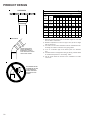
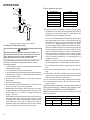
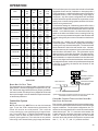
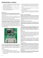
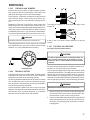
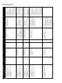
1
Service Instructions
97% Modulating Gas Furnaces
34.5" Chassis ACVM, AMVM, GCVM, GMVM
& Accessories
This manual is to be used by qualified, professionally trained HVAC technicians only. Goodman does
not assume any responsibility for property damage or personal injury due to improper service
procedures or services performed by an unqualified person.
RS6612009r1
November 2014
is a registered trademark of Maytag Corporation or its related companies and is used under license to Goodman Company, L.P., Houston, TX. All rights reserved.
Copyright © 2014 Goodman Company, L.P.
1
TABLE OF CONTENTS
IMPORTANT INFORMATION ...................... 2-4
OPERATIONAL CHECKS ...................... 49 - 51
PRODUCT IDENTIFICATION .................... 5 - 8
MAINTENANCE ...................................... 52
ACCESSORIES ................................... 9 - 11
SERVICING TABLE OF CONTENTS ................ 53
LIGHTING INSTRUCTIONS ......................... 12
SERVICING ..................................... 54 - 60
PRODUCT DESIGN ............................ 13 - 24
TROUBLESHOOTING .......................... 61 - 65
OPERATION .................................... 25 - 47
STATUS CODES ...................................... 66
SERVICE AND OPERATION ......................... 48
WIRING DIAGRAM ................................... 67
IMPORTANT INFORMATION
Pride and workmanship go into every product to provide our customers with quality products. It is possible,
however, that during its lifetime a product may require service. Products should be serviced only by a qualified
service technician who is familiar with the safety procedures required in the repair and who is equipped with the
proper tools, parts, testing instruments and the appropriate service manual. REVIEW ALL SERVICE INFORMATION
IN THE APPROPRIATE SERVICE MANUAL BEFORE BEGINNING REPAIRS.
IMPORTANT NOTICES FOR CONSUMERS AND SERVICERS
RECOGNIZE SAFETY SYMBOLS, WORDS AND LABELS
WARNING
TO PREVENT
THE RISK OF PROPERTY DAMAGE, PERSONAL INJURY, OR DEATH,
DO NOT STORE COMBUSTIBLE MATERIALS OR USE GASOLINE OR OTHER
FLAMMABLE LIQUIDS OR VAPORS IN THE VICINITY OF THIS APPLIANCE.
WARNING
G OODMAN W ILL NOT BE RESPONSIBLE FOR ANY INJURY OR PROPERTY DAM AGE ARISING FROM IMPROPER SERVICE OR SERVICE PROCEDURES.
IF YOU INSTALL OR PERFORM SERVICE ON THIS UNIT, YOU A SSUME RESPONSIBILITY FOR ANY PERSONAL INJURY OR PROPERTY DAMAGE WHICH
MAY RESULT. M ANY JURISDICTIONS REQUIRE A LICENSE TO INSTALL OR SERVICE HEATING AND AIR CONDITIONING EQUIPMENT.
WARNING
HIGH VOLTAGE
DISCONNECT ALL POWER BEFORE SERVICING OR
INSTALLING THIS UNIT. MULTIPLE POWER SOURCES MAY
BE PRESENT. FAILURE TO DO SO MAY CAUSE PROPERTY
DAMAGE, PERSONAL INJURY OR DEATH.
2
IMPORTANT INFORMATION
To locate an authorized servicer, please consult your telephone book or the dealer from whom you purchased this
product. For further assistance, please contact:
CONSUMER INFORMATION LINE
GOODMAN® BRAND PRODUCTS
TOLL FREE
1-877-254-4729 (U.S. only)
email us at:
[email protected]
fax us at: (731) 856-1821
(Not a technical assistance line for dealers.)
CONSUMER INFORMATION LINE
AMANA® BRAND PRODUCTS
TOLL FREE
1-877-254-4729 (U.S. only)
email us at: [email protected]
fax us at: (731) 856-1821
(Not a technical assistance line for dealers.)
Outside the U.S., call 1-713-861-2500.
(Not a technical assistance line for dealers.) Your telephone company will bill you for the call.
3
IMPORTANT INFORMATION
CO can cause serious illness including permanent brain
damage or death.
B10259-216
Advertencia especial para la instalación de calentadores ó manejadoras
de aire en áreas cerradas como estacionamientos ó cuartos de servicio.
Las emisiones de monóxido de carbono pueden circular a través
del aparato cuando se opera en cualquier modo.
El monóxido de carbono puede causar enfermedades severas
como daño cerebral permanente ó muerte.
B10259-216
RISQUE D'EMPOISONNEMENT AU MONOXYDE DE CARBONE
Cette ventilation est nécessaire pour éviter le danger d'intoxication
au CO pouvant survenir si un appareil produisant du monoxyde
de carbone continue de fonctionner au sein de la zone confinée.
B10259-216
is a registered trademark of Maytag Corporation or its related companies and is used under license to Goodman Company, L.P., Houston, TX. All rights reserved.
4
PRODUCT IDENTIFICATION
G
PRODUCT
TYPE:
G: Goodman®
Brand
A: Amana®
Brand
M
V
M
97
060
3
B
N
FURNACE TYPE
V: Variable-Speed
CABINET
WIDTH
B: 17-1/2"
C: 21"
D: 24-1/2"
A
A
MAJOR
REVISION
A: Initial Release
MINOR
REVISION
A: Initial Release
NOMINAL INPUT
060: 60,000 Btuh
080: 80,000 Btuh
100: 100,000 Btuh
120: 120,000 Btuh
ADDITIONAL
FEATURES
N: Natural Gas
X: Low NOx
SUPPLY TYPE
M: Upflow/Horizontal
C: Downflow/Horizontal
AFUE
97: 97%
COMMUNICATION FEATURE
M: Modulating Furnace
4-Wire Communication Ready
AIRFLOW
CAPABILITY
@ 0.5" ESP
3: 1200
4: 1600
5: 2000
5
PRODUCT IDENTIFICATION
MODEL: AMVM97
REV AA
MODEL: ACVM97
REV AA
Equipment Type
Amana Brand Residential Gas Furnace
Equipment Type
Amana Brand Residential Gas Furnace
Heating Stages
Modulating (35% - 100% of rated input)
Heating Stages
Modulating (35% - 100% of rated input)
Cooling Stages
Two
Cooling Stages
Two
Control Type
ClimateTalk ™ or Conventional 24 Volt
Control Type
ClimateTalk ™ or Conventional 24 Volt
Blower Motor Type
4 Wire Variable Speed ECM
Blower Motor Type
4 Wire Variable Speed ECM
AMVM97
Installation Positions
0603BN
0803BN
0804CN
1005CN
1205DN
UF, Hor L/R UF, Hor L/R UF, Hor L/R UF, Hor L/R UF, Hor L/R
BTUH Input Range (X 1000)
21 - 60
28 - 80
28 -80
35 - 100
42 - 120
A/C Capable Tons
1.5 - 3
1.5 - 3
2-4
2- 5
34.5
34.5
34.5
34.5
Cabinet Hight "
ACVM97
Installation Positions
0603BN
0803BN
0804CN
1005CN
CF, Hor L/R CF, Hor L/R CF, Hor L/R CF, Hor L/R
BTUH Input Range (X 1000)
21 - 60
28 - 80
28 -80
2-5
A/C Capable Tons
1.5 - 3
1.5 - 3
2-4
2-5
34.5
Cabinet Hight "
34.5
34.5
34.5
34.5
35 - 100
Cabinet Width "
17.5
17.5
21
21
24.5
Cabinet Width "
17.5
17.5
21
21
Heating CFM @ 100% Firing Rate
1059
1316
1337
1870
1940
Heating CFM @ 100% Firing Rate
950
1146
1325
1779
ECM Motor H.P.
ECM Motor H.P.
Draft Inducer
3Ø Variable Speed
Draft Inducer
3Ø Variable Speed
Gas Valve
24 VAC, Modulates by Pneumatic signal
Gas Valve
24 VAC, Modulates by Pneumatic signal
24 VAC Heating Inputs
W1 / W2
24 VAC Heating Inputs
W1 / W2
24 VAC Cooling Inputs
Y1 / Y2
24 VAC Cooling Inputs
Y1 / Y2
Primary Heat Exchanger
Stainless Steel
Primary Heat Exchanger
Stainless Steel
Accessory Terminals
EAC terminal, HUM IN / HUM OUT terminals
Accessory Terminals
EAC terminal, HUM IN / HUM OUT terminals
Gas Line Entry
Left or Right
Gas Line Entry
Left or Right
Revision Attributes
First revision of 34.5" modulating up flow furnace
Revision Attributes
First revision of 34.5" modulating counter flow furnace
MODEL: GMVM97
REV AA
MODEL: GCVM97
REV AA
Equipment Type
Goodman Brand Residential Gas Furnace
Equipment Type
Goodman Brand Residential Gas Furnace
Heating Stages
Modulating (35% - 100% of rated input)
Heating Stages
Modulating (35% - 100% of rated input)
Cooling Stages
Two
Cooling Stages
Two
Control Type
ClimateTalk ™ or Conventional 24 Volt
Control Type
ClimateTalk ™ or Conventional 24 Volt
Blower Motor Type
4 Wire Variable Speed ECM
Blower Motor Type
4 Wire Variable Speed ECM
GMVM97
Installation Positions
0603BN
0803BN
0804CN
1005CN
1205DN
UF, Hor L/R UF, Hor L/R UF, Hor L/R UF, Hor L/R UF, Hor L/R
BTUH Input Range (X 1000)
21 - 60
28 - 80
28 -80
35 - 100
42 - 120
A/C Capable Tons
1.5 - 3
1.5 - 3
2-4
2- 5
34.5
34.5
34.5
34.5
Cabinet Hight "
28 - 80
28 -80
1.5 - 3
2-4
2-5
34.5
Cabinet Hight "
34.5
34.5
34.5
34.5
Cabinet Width "
17.5
17.5
21
21
Heating CFM @ 100% Firing Rate
950
1146
1325
1779
17.5
21
21
24.5
1337
1870
1940
24 VAC Heating Inputs
W1 / W2
24 VAC Cooling Inputs
Y1 / Y2
Primary Heat Exchanger
Aluminized Steel
Accessory Terminals
EAC terminal, HUM IN / HUM OUT terminals
Gas Line Entry
Left or Right
Revision Attributes
First revision of 34.5" modulating up flow furnace
6
CF, Hor L/R CF, Hor L/R CF, Hor L/R CF, Hor L/R
1.5 - 3
1316
24 VAC, Modulates by Pneumatic signal
1005CN
21 - 60
17.5
Gas Valve
0804CN
A/C Capable Tons
1059
3Ø Variable Speed
0803BN
2-5
Heating CFM @ 100% Firing Rate
Draft Inducer
Installation Positions
0603BN
BTUH Input Range (X 1000)
Cabinet Width "
ECM Motor H.P.
GCVM97
35 - 100
ECM Motor H.P.
Draft Inducer
3Ø Variable Speed
Gas Valve
24 VAC, Modulates by Pneumatic signal
24 VAC Heating Inputs
W1 / W2
24 VAC Cooling Inputs
Y1 / Y2
Primary Heat Exchanger
Aluminized Steel
Accessory Terminals
EAC terminal, HUM IN / HUM OUT terminals
Gas Line Entry
Left or Right
Revision Attributes
First revision of 34.5" modulating counter flow furnace
PRODUCT IDENTIFICATION
MODEL #
MFG #
DESCRIPTION
AFE18-60A
N/A
Fossil Fuel Kit. The AFE18-60A control is designed for use where the indoor coil is located above/downstream
of a gas or fossil fuel furnace when used with a heat pump. It will operate with single and two stage heat
pumps and single and two stage furnaces. The AFE18-60A control will turn the heat pump unit off when the
furnace is turned on. An anti-short cycle feature initiates a 3 minute timed off delay when the compressor goes
off.
AMU1620
AMU1625
AMU2020
AMU2025
P1251305F
P1251306F
P1251307F
P1251308F
GMU1620
GMU1625
GMU2020
GMU2025
N/A
ASAS-10
ASAS-11
ASAS-12
ASAS-18
P1251301F
P1251302F
P1251303F
P1251304F
Media Air Cleaner. For use with current architectural grey Goodman® and Amana® Brand 96% variable speed,
modulating furnace models. The Amana (AMU*) and Goodman (GMU*) Media Air Cleaner is a high efficiency
air filtration device designed to remove dirt, dust, pollen and other microscopic particles from the air passing
through it. Flexible performance range up to 2,000 CFM capacity. The air cleaner should be installed in the
system so that all the system air is circulated through the air cleaner. The air cleaner will only remove the
airborne contaminants delivered to it. Maximum performance is obtained when the system blower is set for
continuous operation. Carbon filters (optional) are available.
Electronic Air Cleaner. For use with current architectural grey Goodman® and Amana® Brand 96% variable
speed, modulating furnace models. The High-Efficiency Electronic Air Cleaner is designed to remove air
contaminants down to .01 microns. Carbon filters (optional) remove odors. Dual indicator lights show unit
operation at a glance. Electronic proving switch cycles the air cleaner On/Off with the system fan. Durable
powder-coat paint finish resists corrosion.
N/A
Counterflow Subbase Kit. For use with Goodman®, & Amana® Brand modulating 34.5" furnace models.
These kits are available for the following furnace widths: 17.5" wide (CFSB17), 21" wide (CFSB21) and 24"
wide (CFSB24). The kits must be used to prevent excessive temperature from reaching combustible materials,
if the furnace is installed on a combustible floor. This subbase effectively separated the furnace base and
plenum from combustible materials. To ensure safe installation, do not install the counterflow floor base
directly on carpeting, tile, or other combustible material other than wood flooring.
CTK01AA
Communicating Thermostat Kit- Digitally communicating touchscreen thermostat, a necessary part of any
communicating system. Designed for use with compatible Amana® Brand or Goodman® Brand Air Handlers
or Furnaces and outdoor split AC or Heat Pump units. This thermostat supports up to three stages of heat, two
stages of cooling, dual fuel applications, dehumidification, filter maintenance reminders, outdoor temperature
display and advanced menus including diagnostics. The CTK01AA kit includes a communicating touchscreen
thermostat and sub base, 230V-24V 40va transformer, terminal blocks(2), wire jumpers,
mounting screws, installation manual and homeowner guide.
CTK01BA
Communicating Thermostat Kit- Digitally communicating touchscreen thermostat, a necessary part of any
communicating system. Designed for use with compatible Amana® Brand or Goodman® Brand Air Handlers
or Furnaces and outdoor split AC or Heat Pump units. This thermostat supports up to three stages of heat, two
stages of cooling, dual fuel applications, dehumidification, filter maintenance reminders, outdoor temperature
display and advanced menus including diagnostics. The CTK01BA kit includes a communicating touchscreen
thermostat and sub base, terminal blocks(2), mounting screws, installation manual and homeowner guide.
CTK02**
CTK02**
Communicating Thermostat Kit- Digitally communicating thermostat, a necessary part of any communicating
system. Designed for use with compatible Amana® Brand or Goodman® Brand Air Handlers or Furnaces and
outdoor split AC or Heat Pump units. The CTK02** thermostat features full color, high definition display,
advanced programming options including humidification control & heat and cool maximum temperature
settings, a USB plug allowing dealers the ability to insert pre-programmed operating parameters and dealer
information by use of an online data entry system.
CTK03A*
CTK03A*
Communicating Thermostat Kit- Digitally communicating touchscreen thermostat from Honeywell. Designed
for use with compatible Amana® Brand or Goodman® Brand Air Handlers or Furnaces and outdoor split AC or
Heat Pump units. The CTK03A* thermostat features full color high definition display, can be used with
RedLINK wireless accessories.
CTK04A*
Communicating Thermostat Kit- Digitally communicating touchscreen thermostat from Honeywell. Designed
for use with compatible Amana® Brand or Goodman® Brand Air Handlers or Furnaces and outdoor split AC or
Heat Pump units. The CTK04A* thermostat features full color high definition display, can be used with
RedLINK wireless accessories. Split system inverter capable.
CFSB17
CFSB21
CFSB24
CTK01
CTK01BA
CTK04A*
7
PRODUCT IDENTIFICATION
MODEL #
MFG #
DESCRIPTION
N/A
Concentric Vent Kit. For use with Amana® Brand Modulating furnace models. This kit is designed to allow
terminations of a direct vent furnace to be "concentrically" vented through a wall or roof. This kit allows a single
penetration to support terminations for both the vent/flue and the combustion air intake pipe. The DCVK-20 (2")
and DCVK-30 (3") kits are certified for models listed above. See specification sheets on future models for use
of the vent kit.
P1227801F
Dehumidistat. For use with Goodman® & Amana® Brand two-stage variable speed modulating furnace
models. Wall mounted, 24 volt humidity control available as a Dehumidistat used to reduce the airflow in the air
conditioning mode when necessary to lower the humidity in an occupied home to prevent dew build-up
associated with high humidity levels. This control features a moisture-sensitive nylon element and also
provides positive ON-OFF settings for manual operation. The control is a normally closed switch that opens on
humidity rise causing the blower to switch to a lower speed to control the humidity within the structure.
EFR02
N/A
External Filter Rack Kit. For use with Goodman® and Amana® Brand 97% upflow, variable speed *MVM 34.5"
modulating gas furnaces. This kit is intended to provide a location, external to the furnace casing for installation
of a permanent filter. The rack is mounted over the indoor air blower compartment area of either side panel,
and provide filter retention as well as a location for attaching return air ductwork.
0170K00000S
N/A
Side Wall Only Concentric Vent Kit. For use with 96% modulating furnace models. This kit is to be used with
2" - 3" vent systems. The vent kit must terminate outside the structure. This kit is NOT intended for use with
single pipe (indirect vent) installations.
0170K00001S
N/A
Side Wall Only Concentric Vent Kit. For use with 96% modulating furnace models. This kit is to be used with
2" vent systems. The vent kit must terminate outside the structure. This kit is NOT intended for use with single
pipe (indirect vent) installation
LPLP03
N/A
LP Gas Low Pressure Kit. Designed for application on Goodman® and Amana® Brand's 80% and 90% singlestage, two-stage and modulating furnaces converted to LP gas. The kit monitors gas line pressure with a
pressure switch and will open the circuit to the gas valve if the LP tank pressure gets low.
LPM-09
N/A
LP Conversion Kit Converts a 34.5" modulating furnace to operate on L.P. gas. The kit contains an L.P. gas
valve and a set of six L.P. orifices.
RF000142
N/A
Drain Coupling Kit For use when the drain/vent elbow has been removed in a horizontal left installation. This
kit prevents condensate from getting in the inducer and routes the condensate to a drain.
DCVK-20
(CVENT-2)
DCVK-30
(CVENT-3)
DEHUM1
8
MFG. #
DESCRIPTION
PCBKF201
1st Revision to
Modulating Control
Board
Software revision to allow ECM motor to store shared data
PCBKF202
2nd Revision to
Modulating Control
Board
Software revision for operation with Daikin Inverter
DCVK-20
DCVK-30
DEHUM1
EFR02
LPLP03
Concentric Vent Kit (2")
Concentric Vent Kit (3")
Dehumidistat
External Filter Kit
Low LP Tank Protection
X
X
X
X
X
X
X
X
X
X
X
X
X
X
X
*MVM970804CN**
X
X
X
X
X
X
X
X
*MVM971005CN**
X
X
X
X
X
X
X
X
*MVM971205DN**
X
X
X
X
X
X
X
X
*CVM970603BN**
X
X
X
X
X
X
X
X
*CVM970803BN**
X
X
X
X
X
X
X
X
*CVM970804CN**
X
X
X
X
X
X
X
X
*CVM971005CN**
X
X
X
X
X
X
X
X
L.P. Kit
Vent Kit (2")
Concentric Side Wall
Vent Kit (3")
Model
X
*MVM970803BN**
LPM-09
0170K00001S
0170K00000S
Number
*MVM970603BN**
Concentric Side Wall
Description
AMU / GMU
Media Air Cleaners
X
X
X
X
X
X
X
X
*MVM970803BN**
X
X
X
X
X
X
X
X
*MVM970804CN**
X
X
X
X
X
X
X
X
*MVM971005CN**
X
X
X
X
X
X
X
X
*MVM971205DN**
X
X
X
X
X
X
X
X
*CVM970603BN**
X
X
X
X
X
X
X
X
X
*CVM970803BN**
X
X
X
X
X
X
X
X
X
*CVM970804CN**
X
X
X
X
X
X
X
X
X
*CVM971005CN**
X
X
X
X
X
X
X
X
X
Modulating, High Def
Com Thermostat Kit-
Modulating, High Def
Com Thermostat Kit-
Modulating, High Def.
Com Thermostat Kit-
Thermostat Kit
Communicating
Kit
Drain Coupling
21"
Counterflow Subbase
17.5"
Counterflow Subbase
Air Cleaner
Electronic
AFE180-60A
Model
*MVM970603BN**
CTK04*
CTK03*
CTK02*
CTK01*
RF000142
CFSB21
CFSB17
ASAS / GSAS
Number
Fossil Fuel Kit
Description
ACCESSORIES
97% Mod Furnace Accessories
9
ACCESSORIES
EXTERNAL FILTER RACK (EFR02)
Used on 97% Upflow Modulating Furnaces
SLOTS IN FILTER
CLEAR SCREWS
ON UNIT
BLOWER DECK
SCREWS
UNIT SIDE
PANEL
FRONT
OF UNIT
FILTER RACK ASSEMBLY
(FACE FILTER OPENING
TOWARDS FRONT
OF UNIT)
BASE
OF UNIT
RETURN AIR
CUTOUT AREA
LOWER EDGE
SCREW
CONCENTRIC VENT CONVERSION KIT (DCVK-20 & DCVK-30 [CVENT-2 & CVENT-3*])
The DCVK-20 (2") or the DCVK-30 (3") is a concentric vent See the section in this manual under "Vent Flue and Comkit approved with furnaces listed in this manual.
This concentric vent kit allows for vertical or horizontal
vent termination. The illustrations give a brief view of
the kit and its application.
bustion Air Pipe Terminations" for more information or
consult the Installation and Operating Instructions (IOVent
619*).
Combustion Air
Vent
Strap
(Field Supplied)
Maintain 12" (18" for Canada)
minimum clearance above highest
anticipated snow level. Maximum of
24" above roof.
Combustion Air
Roof Boot/Flashing
(Field Supplied)
Vent
Support (Field Supplied)
Flush to
1" maximum
Combustion Air
45 Elbow
(Field Supplied)
45 Elbow
(Field Supplied)
Vent
DCVK
(Horizontal Installation)
DCVK-20 & DCVK-30 are also known as CVENT-2 & CVENT-3
10
DCVK
(Vertical Installation)
Combustion Air
ACCESSORIES
SIDE WALL VENT KIT (0170K00000S)
LPM-09 LP CONVERSION KIT
This side wall only vent kit #0170K00000S is to be used
with 2” - 3” vent systems. This kit is NOT intended for
use with single pipe (non-direct vent) installations.
The vent kit must terminate outside the structure and may
be installed with the intake and exhaust pipes located sideby-side or with one pipe above the other.
See the section in this manual under "Vent Flue and Combustion Air Pipe Terminations" for more information or
consult the Installation Instructions (IO-635).
This furnace is factory equipped to operate on Natural Gas
but may be field converted to operate on LP gas. To convert a *MVM97 or *CVM97 furnace to operate on LP gas,
the LPM-09 conversion kit must be used. The LPM-09 kit
contains a modulating gas valve ready for use with LP gas,
as well as a set of 1.25 mm orifices to replace the factory
installed natural gas orifices. Do not attempt to convert or
adjust a modulating furnace gas valve. Factory burners
are suitable for both gases, L.P. and Natural. Burner replacement is not required when the furnace is converted
for use with L.P. gas.
SIDE WALL VENT KIT (0170K00001S)
This side wall only vent kit #0170K00001S is to be used
with 2” vent systems. This kit is NOT intended for use
with single pipe (non-direct vent) installations.
The vent kit must terminate outside the structure and may
be installed with the intake and exhaust pipes located sideby-side or with one pipe above the other.
See the section in this manual under "Vent Flue and Combustion Air Pipe Terminations" for more information or
consult the Installation Instructions (IO-805).
AFE18-60A DUAL FUEL ACCESSORY
When installing the modulating furnace with a heat pump,
the preferred installation would include a communicating
thermostat. A communicating thermostat provides control
of gas heat and heat pump operation and eliminates the
need for a separate dual fuel control. A legacy dual fuel
thermostat could also be used with 24 volt wiring to control the gas furnace and heat pump. If a communicating
thermostat or legacy dual fuel thermostat are not used,
the AFE18-60A kit must be added to provide control of the
equipment. This control is mounted indoors near the furnace and provides terminals for thermostat, furnace, and
heat pump wiring. The AFE18-60A may be used with or
without a separate outdoor thermostat.
OT18-60A OUTDOOR THERMOSTAT
For use in a legacy dual fuel installation to lock-out the
heat pump at a selected temperature.
LPLP03 LOW LP GAS PRESSURE SHUT-OFF KIT
Installation of the LPLP03 kit is recommended on every LP
converted furnace to protect the furnace against low LP
gas supply pressure. Low LP supply pressure can cause poor
combustion and carbon in the heat exchanger. The LPLP03
kit will open the electrical circuit to the gas valve in the
event of low supply pressure. The kit contains a pressure
switch, gas fittings and electrical harness to connect the
switch in series with the gas valve.
CFSB17, 21, 24 COUNTER FLOW BASE
The CFSB base must be used when installing a *CVC97 furnace in the vertical position on a combustible floor without
a coil under the furnace.
11
LIGHTING INSTRUCTIONS
FOR YOUR SAFETY
READ BEFORE OPERATING
WARNING: If you do not follow these instructions
Exactly, a fire or explosion may result causing property
damage, personal injury or loss of life.
A. This appliance does not have a pilot. It is equipped
with an ignition device which automatically lights
the burner. Do not try to light the burner by hand.
B. BEFORE OPERATING smell all around the appliance
area for gas. Be sure to smell next to the floor
LIRE AVANT DE METTRE
EN MARCHELIRE
AVERTISSEMENT: Quiconque ne respecte pas à
la lettre les instructions dans le presént manuel
risque de déclencher un incendie ou une explosion
entraînant des dommages matériels, des lesions
corporelles ou la perte de vies humaines.
A.Cet appareil ne comporte pas de veilleuse. Il est
muni d'un dispositif d'allumage qui allume
automatiquement le brûleur. Ne pas tenter
d'allumer le brûleur manuellement.
B. AVANT DE LE FAIRE FONCTIONNER,
er
settle on the floor.
WHAT TO DO IF YOU SMELL GAS
Do not try to light any appliance.
Do not touch any electric switch;
do not use any phone in your building.
Immediately call your gas supplier from a neighbor's
phone. Follow the gas supplier's instructions.
If you cannot reach your gas supplier,
call the fire department.
C. Use only your hand to push in or turn the gas control lever.
Never use tools. If the lever will not push in or turn by
hand, don't try to repair it, call a qualified service
technician. Force or attempted repair may result in a fire
or explosion.
D. Do not use this appliance if any part has been underwater.
Immediately call a qualified service technician to inspect
the appliance and to replace any part of the control
system and any gas control which has been underwater.
OPERATING INSTRUCTIONS
une odeur de gaz. Renifler prés du plancher, car
certains gaz sont plus lourds que l'air et
peuvent s'accumuler au niveau du sol.
QUE FAIRE S'IL Y A UNE ODEUR DE GAZ
Ne pas tenter d'allumer d'appareils.
Ne toucher à aucun interrupteur; ne pas vous servir
des téléphones dans le bâtiment.
Appelez immédiatement votre fournisseur de gaz depuis
un voisin. Suivez les instructions du fournisseur de gaz
Si vous ne pouvez rejoindre le fournisseur de gaz,
appelez le service des incendies.»
C. Ne pousser ou tourner la manette d'admission du gaz
qu'à la main. Ne jamais emploer d'outil à cette fin.
Si la manette reste coincée, ne tenter pas de la
réparer; appelez un technicien qualifié. Quiconque
tente de forcer la manette ou de la réparer peut
provoquer une explosion ou un incendie.»
D. Ne pas se servir de cet appareil s'il a été plongé dans
l'eau, même partiellement. Faire inspecter l'appareil
par un technicien qualifié et remplacer toutr partie du
systéme de contrôle et toute commande qui ont été
plongées dans l'eau.»
MISE EN MARCHE
1. ARRÊTEZ
Lisez les instructions de sécurité dans la
1. STOP! Read the safety information above on
this label.
. section supérieure de cette étiquette.
2. Régler le thermostat à la température la plus basse.
2. Set the thermostat to lowest setting.
3. Couper l'alimentation électrique de l'appareil.
3. Turn off all electric power to the appliance.
4. Cet appareil menager etant dote d'un systeme
4. This appliance is equipped with an ignition
d'allumage automatique, ne pas essayer à
device which automatically lights the burner.
allumer le brûleur manuellement.
Do not try to light the burner by hand.
5. Pousse le levier du contrÔle du gaz a "OFF/ ARRET"
5. Push the gas control lever to "OFF" Position.
position.
Do not force.
6. Attendre cinq (5) minutes pour laisser echapper tout le
6. Wait five (5) minutes to clear out any gas. Then
gaz. Renifler tout autour de l'appareil, y compris prés du
smell for gas, including near the floor. If you
plancher, pour déceler une odeur de gaz. Si c'est le cas,
then smell gas, STOP. Follow "B"
ROBINET A GAZ
ARRÊTEZ. Passer à l'etape B des instructions de securite
in the safety. information above
MANUEL, EN POS sur la portion superieure de cette etiquette.
on this label if you don't smell
"ON/MARCHE"
S'il n'y a pas d'odeur de gaz, passer à l'etàpe suivante.
gas, go to next step.
GAS
7. Pousse le levier du contrôle du gaz à "ON/MARCHE"
7. Push gas control lever
INLET
position.
to "ON".
8. Remettre en place le panneau d'accés.
8. Replace access panel.
9. Mettre l'appareil sous tension.
ARRIVEE
9. Turn on all electric
DU GAZ
10. Régler le thermostat à la température désirée.
power to the appliance.
11. Si l'appareil ne se met pas en marche, suivre les
10. Set thermostat to desired setting.
instructions intitulées Comment couper l'admission
MANUAL GAS
11. If the appliance will not operate,
de gaz de l'appareil et appeler un technicien
LEVER SHOWN
follow the instructions "To Turn
IN "ON" POS
qualifié ou le fournisseur de gaz.
Off Gas To Appliance" and call your
service technician or gas company.
TO TURN OFF GAS TO APPLIANCE
1. Set the thermostat to lowest setting.
2. Turn off all electric power to the appliance
if service is to be performed.
3. Push the gas control lever to "OFF" Position.
Do not force.
4. Replace control access panel.
POUR COUPER L'ADMISSION
DE GAZ DE L'APPAREIL
1. Régler le thermostat à la température la plus bassé.
2. Couper l'alimentation électrique de l'appareil s'il
faut procéder à des operations d'entretien.
3. Pousse le levier du contrôle du gaz à "OFF/ ARRET"
position.
Ne pas forcer.
4. Remettre en place le panneau d'accés.
0140F00996 REV A
12
PRODUCT DESIGN
Adhere to the following warnings and cautions when installing, adjusting, altering, servicing, or operating the
furnace. To ensure proper installation and operation,
thoroughly read this manual for specifics pertaining to the
installation and application of this product.
WARNING
T O PREVENT POSSIBLE PROPERTY DAMAGE, PERSONAL INJURY OR
DEATH DUE TO ELECTRICAL SHOCK , THE FURNACE MUST BE LOCATED TO
PROTECT THE ELECTRICAL COMPONENTS FROM WATER.
WARNING
T O PREVENT PERSONAL INJURY OR DEATH DUE TO IMPROPER
INSTALLATION, ADJUSTMENT, ALTERATION, SERVICE OR MAINTENANCE,
REFER TO THIS MANUAL . FOR ADDITIONAL ASSISTANCE OR
INFORMATION, CONSULT A QUALIFIED INSTALLER , SERVICER AGENCY OR
THE GAS SUPPLIER .
WARNING
IF THE INFORMATION IN THESE INSTRUCTIONS IS NOT FOLLOWED
EXACTLY , A FIRE OR EXPLOSION MAY RESULT CAUSING PROPERTY
DAMAGE , PERSONAL INJURY OR LOSS OF LIFE.
DO NOT STORE OR USE GASOLINE OR OTHER FLAMMABLE VAPORS AND
LIQUIDS IN THE VICINITY OF THIS OR ANY OTHER APPLIANCE .
WHAT TO DO IF YOU SMELL GAS:
D O NOT TRY TO LIGHT ANY APPLIANCE.
D O NOT TOUCH ANY ELECTRICAL SWITCH; DO NOT USE ANY PHONE
IN YOUR BUILDING .
IMMEDIATELY CALL YOUR GAS SUPPLIER FROM A NEIGHBOR’S
PHONE. FOLLOW THE GAS SUPPLIER’ S INSTRUCTIONS.
IF YOU CANNOT REACH YOUR GAS SUPPLIER, CALL THE FIRE
DEPARTMENT.
INSTALLATION AND SERVICE MUST BE PERFORMED BY A QUALIFIED
INSTALLER, SERVICE AGENCY OR THE GAS SUPPLIER.
WARNING
CO can cause serious illness including permanent brain
damage or death.
B10259-216
Advertencia especial para la instalación de calentadores ó manejadoras
de aire en áreas cerradas como estacionamientos ó cuartos de servicio.
T HIS PRODUCT CONTAINS OR PRODUCES A CHEMICAL OR CHEMICALS
WHICH MAY CAUSE SERIOUS ILLNESS OR DEATH AND WHICH ARE
KNOWN TO THE S TATE OF CALIFORNIA TO CAUSE CANCER, BIRTH
DEFECTS OR OTHER REPRODUCTIVE HARM .
WARNING
HEATING UNIT SHOULD NOT BE UTILIZED WITHOUT REASONABLE,
ROUTINE , INSPECTION , MAINTENANCE AND SUPERVISION . IF THE
BUILDING IN WHICH ANY SUCH DEVICE IS LOCATED WILL BE VACANT,
Las emisiones de monóxido de carbono pueden circular a través
del aparato cuando se opera en cualquier modo.
El monóxido de carbono puede causar enfermedades severas
como daño cerebral permanente ó muerte.
B10259-216
RISQUE D'EMPOISONNEMENT AU MONOXYDE DE CARBONE
CARE SHOULD BE TAKEN THAT SUCH DEVICE IS ROUTINELY INSPECTED,
MAINTAINED AND MONITORED. IN THE EVENT THAT THE BUILDING
MAYBE EXPOSED TO FREEZING TEMPERATURES AND WILL BE VACANT,
ALL WATER -BEARING PIPES SHOULD BE DRAINED, THE BUILDING SHOULD
BE PROPERLY WINTERIZED, AND THE WATER SOURCE CLOSED . IN THE
EVENT THAT THE BUILDING MAY BE EXPOSED TO FREEZING
TEMPERATURES AND WILL BE VACANT, ANY HYDRONIC COIL UNITS
SHOULD BE DRAINED AS WELL AND , IN SUCH CASE, ALTERNATIVE HEAT
Cette ventilation est nécessaire pour éviter le danger d'intoxication
au CO pouvant survenir si un appareil produisant du monoxyde
de carbone continue de fonctionner au sein de la zone confinée.
SOURCES SHOULD BE UTILIZED.
B10259-216
13
PRODUCT DESIGN
WARNING
SHOULD OVERHEATING OCCUR OR THE GAS SUPPLY FAIL TO SHUT OFF,
TURN OFF THE MANUAL GAS SHUTOFF VALVE EXTERNAL TO THE
FURNACE BEFORE TURNING OFF THE ELECTRICAL SUPPLY.
WARNING
POSSIBLE PROPERTY DAMAGE , PERSONAL INJURY OR DEATH DUE TO
FIRE, EXPLOSION , SMOKE, SOOT, CONDENSATION, ELECTRICAL SHOCK
OR CARBON MONOXIDE MAY RESULT FROM IMPROPER INSTALLATION,
REPAIR OPERATION, OR MAINTENANCE OF THIS PRODUCT.
Electrostatic Discharge (ESD) Precautions
NOTE: Discharge your body’s static electricity before touching unit. An electrostatic discharge can adversely affect
electrical components.
Use the following precautions during furnace installation
and servicing to protect the integrated control module from
damage. By putting the furnace, the control, and the person at the same electrostatic potential, these steps will
help avoid exposing the integrated control module to electrostatic discharge. This procedure is applicable to both
installed and non-installed (ungrounded) furnaces.
1. Disconnect all power to the furnace. Do not touch
the integrated control module or any wire connected
to the control prior to discharging your body’s electrostatic charge to ground.
2. Firmly touch a clean, unpainted, metal surface of the
furnaces near the control. Any tools held in a
person’s hand during grounding will be discharged.
3. Service integrated control module or connecting wiring following the discharge process in step 2. Use
caution not to recharge your body with static electricity; (i.e., do not move or shuffle your feet, do
not touch ungrounded objects, etc.). If you come in
contact with an ungrounded object, repeat step 2 before touching control or wires.
4. Discharge your body to ground before removing a
new control from its container. Follow steps 1
through 3 if installing the control on a furnace. Return any old or new controls to their containers before touching any ungrounded object.
WARNING
TO PREVENT PROPERTY DAMAGE , PERSONAL INJURY OR DEATH DUE TO
FIRE, DO NOT INSTALL THIS FURNACE IN A MOBILE HOME, TRAILER, OR
RECREATIONAL VEHICLE.
Introduction
This is a Category lV furnace. This furnace uses a pressurized venting system and must be installed per National and
local codes requirements and the installation manual that
was shipped with the furnace.
14
Our 34.5" modulating furnace is one of the products in our
newly redesigned line of shorter chassis furnaces. It comes
in two models: an up flow / horizontal model and a down
flow / horizontal model.
The up flow / horizontal 34.5" modulating furnace is available in the following nominal capacities: 60,000 BTUH – 3
ton drive; 80,000 BTUH – 3 ton drive; 80,000 BTUH – 4 ton
drive; 100,000 BTUH – 5 ton drive; 120,000 BTUH – 5 ton
drive.
*MVM970603BN*
*MVM970803BN*
*MVM970804CN*
*MVM971005CN*
*MVM971205DN*
The down flow / horizontal 34.5" modulating furnace is
available in the following nominal capacities: capacities:
60,000 BTUH – 3 ton drive; 80,000 BTUH – 3 ton drive;
80,000 BTUH – 4 ton drive; 100,000 BTUH – 5 ton drive.
*CVM970603BN*
*CVM970803BN*
*CVM970804CN*
*CVM971005CN*
Product Description
Features
General Information
The modulating furnace is part of the Goodman® brand &
Amana® brand family of communicating ready products.
The furnace may be used with conventional single or multistage thermostats as well as Goodman CTK01 communicating thermostats & CTK02**, CTK03 and CTK04 communicating-modulating thermostats using the ClimateTalk™
communicating protocol. Burner manifold pressure is controlled by negative air pressure created by the draft inducer. Gas valve, pressure switch assembly, and induced
draft blower are linked together by pneumatic tubing. The
furnace features a Honeywell gas valve capable of variable
gas input rates as low as 35% and up to 100% of rated
input. Indoor air is delivered by a variable speed ECM motor which bases the CFM need off of the burner input. The
modulating furnace operation is based off of negative pressure created by the draft inducer. The Integrated Furnace
Control (IFC) receives commands from the room thermostat. The IFC then controls the RPM of the (3 phase) inducer by varying the frequency and voltage to the inducer.
This is known as variable frequency drive (VFD).
PRODUCT DESIGN
Acceptable Equipment Combinations
With CTK0* Communicating Thermostat:
1. Modulating furnace alone
2. Modulating furnace with Goodman® brand / Amana®
brand communicating split A/C or H/P unit (no separate dual fuel control is required)
3. Modulating furnace with non-communicating 1 stage
A/C split unit (can not support a 2 stage A/C or a
non-communicating heat pump).
With Conventional Non-Communicating Thermostat
(Single or Multi-Stage)
1. Modulating furnace alone.
2. Modulating furnace with Goodman® brand/ Amana®
brand communicating split A/C or H/P unit (a dual
fuel thermostat or separate dual fuel control is required for H/P).
3.
Modulating furnace with non-communicating split A/
C or H/P (a dual fuel thermostat or separate dual
fuel control is required for H/P).
Product Application
This furnace is primarily designed for residential homeheating applications. It is NOT designed or certified for
use in mobile homes, trailers or recreational vehicles.
Neither is it designed or certified for outdoor applications.
The furnace MUST be installed indoors (i.e., attic space,
crawl space, or garage area provided the garage area is
enclosed with an operating door).
This furnace can be used in the following non-industrial
commercial applications:
Schools, Office buildings, Churches, Retail stores,
Nursing homes, Hotels/motels,
Common or office areas
In such applications, the furnace must be installed with
the following stipulations:
• It must be installed per the installation instructions provided and per local and national codes.
• It must be installed indoors in a building constructed on
site.
• It must be part of a ducted system and not used in a free
air delivery application.
• It must not be used as a “make-up” air unit.
• It must be installed with two-pipe systems for combustion air.
• All other warranty exclusions and restrictions apply This
furnace is an ETL dual-certified appliance and is appropriate for use with natural or propane gas (NOTE: If
using propane, a propane conversion kit is required).
Dual certification means that the combustion air inlet pipe is
optional and the furnace can be vented as a:
Non-direct vent (single pipe) central forced air furnace
in which combustion air is taken from the installation
area or from air ducted from the outside or,
Direct vent (dual pipe) central forced air furnace in which
all combustion air supplied directly to the furnace burners through a field installed combustion air pipe.
This furnace may be used as a construction site heater ONLY
if all of the following conditions are met:
• The vent system is permanently installed per these installation instructions.
• A room thermostat is used to control the furnace. Fixed
jumpers that provide continuous heating CANNOT be
used and can cause long term equipment damage.
• Return air ducts are provided and sealed to the furnace.
• A return air temperature range between 60ºF (16ºC) and
80ºF (27ºC) is maintained.
• Air filters are installed in the system and maintained
during construction replaced as appropriate during construction, and upon completion of construction.
• The input rate and temperature rise are set per the furnace rating plate.
• 100% outside air is provided for combustion air requirements during construction. Temporary ducting can be
used.
NOTE: Do not connect the temporary duct directly to the
furnace. The duct must be sized for adequate combustion and ventilation in accordance with the latest edition of the National Fuel Gas Code NFPA 54/ANSI Z223.1
or CAN/CSA B149.1 Installation Codes.
• The furnace heat exchanger, components, duct system,
air filters and evaporator coils are thoroughly cleaned
following final construction clean up.
• All furnace operating conditions (including ignition, input rate, temperature rise and venting) are verified
according to these installation instructions.
NOTE: The Commonwealth of Massachusetts requires that
the following additional requirements must also be met:
• Gas furnaces must be installed by a licensed plumber or
gas fitter.
• A T-handle gas cock must be used.
• If the unit is to be installed in an attic, the passageway
to and the service area around the unit must have flooring.
To ensure proper furnace operation, install, operate and
maintain the furnace in accordance with the installation
manual shipped with the furnace as well as all local building codes and ordinances. In their absence, follow the latest
edition of the National Fuel Gas Code (NFPA 54/ANSI Z223.1),
and/or CAN/CSA B149 Installation Codes, local plumbing or
waste water codes, and other applicable codes.
A copy of the National Fuel Gas Code (NFPA 54/ANSI Z223.1)
can be obtained from any of the following:
American National Standards Institute
1430 Broadway
New York, NY 10018
15
PRODUCT DESIGN
National Fire Protection Association
1 Batterymarch Park
Quincy, MA 02269
CSA International
8501 East Pleasant Valley
Cleveland, OH 44131
The rated heating capacity of the furnace should be greater
than or equal to the total heat loss of the area to be heated.
The total heat loss should be calculated by an approved method
or in accordance with “ASHRAE Guide” or “Manual J-Load Calculations” published by the Air Conditioning Contractors of
America.
A copy of the CAN/CSA B149 Installation Codes can also be
obtained from:
CSA International
178 Rexdale Boulevard
Etobicoke, Ontario, Canada M9W 1R3
•
•
FURNACE INSTALLATION REQUIREMENTS
Thoroughly read the Installation Manual shipped with the
furnace before conducting installation or repairs.
• Centrally locate the furnace with respect to the proposed
or existing air distribution system.
•
Ensure the temperature of the return air entering the
furnace is between 55°F and 100°F when the furnace is
heating.
•
Provide provisions for venting combustion products outdoors through a proper venting system. Special consideration should be given to vent/flue pipe routing and
combustion air intake pipe when applicable. Refer to
Vent/Flue Pipe and Combustion Air Pipe -Termination
Locations for appropriate termination locations and to
determine if the piping system from furnace to termination can be accomplished within the guidelines given.
NOTE: The length of flue and/or combustion air piping
can be a limiting factor in the location of the furnace.
•
Locate the furnace so condensate flows downwards to
the drain. Do not locate the furnace or its condensate
drainage system in any area subject to below freezing
temperatures without proper freeze protection. Refer to
Condensate Drain Lines and Trap for further details.
•
Ensure adequate combustion air is available for the furnace. Improper or insufficient combustion air can expose building occupants to gas combustion products that
could include carbon monoxide. Refer to Combustion
and Ventilation Air Requirements.
•
Set the furnace on a level floor to enable proper condensate drainage. If the floor becomes wet or damp at times,
place the furnace above the floor on a concrete base sized
approximately 1-1/2" larger than the base of the furnace. Refer to the Horizontal Applications and Considerations for leveling of horizontal furnaces.
•
Ensure upflow or horizontal furnaces are not installed directly on carpeting, or any other combustible material.
The only combustible material allowed is wood.
16
•
•
•
A special accessory subbase must be used for upright
counterflow unit installations over any combustible material (including wood). Refer to subbase instructions
for installation details. (NOTE: A subbase will not be
required if an air conditioning coil is located beneath the
furnace between the supply air opening and the combustible floor.
Exposure to contaminated combustion air will result in
safety and performance-related problems. Do not install
the furnace where the combustion air is exposed to the
following substances:
permanent wave solutions
chlorinated waxes or cleaners
chlorine-based swimming pool chemicals
water softening chemicals
deicing salts or chemicals
carbon tetrachloride
halogen type refrigerants
cleaning solutions (such as perchloroethylene)
printing inks
paint removers
varnishes
hydrochloric acid
cements and glues
antistatic fabric softeners for clothes dryers
and masonry acid washing materials
Isolate a non-direct furnace from an area contaminated by any of the above substances. This protects
the non-direct vent furnace from airborne contaminants.
To ensure that the enclosed non-direct vent furnace has
an adequate supply of combustion air, vent from a nearby
uncontaminated room or from outdoors. Refer to the
Combustion and Ventilation Air Requirements for details.
If the furnace is used in connection with a cooling
unit, install the furnace upstream or in parallel with
the cooling coil. Premature heat exchanger failure
will result if the cooling coil is placed upstream of the
furnace.
For vertical (upflow or downflow) applications, the
minimum cooling coil width shall not be less than furnace width minus 1”. Additionally, a coil installed
above an upflow furnace or under a counterflow furnace may be the same width as the furnace or may
be one size larger than the furnace. Example: a “C”
width coil may be installed with a “B” width furnace.
For upflow applications, the front of the coil and furnace must face the same direction.
If the furnace is installed in a residential garage, position the furnace so that the burners and ignition source
are located not less than 18 inches (457 mm) above the
floor. Protect the furnace from physical damage by vehicles.
PRODUCT DESIGN
•
If the furnace is installed horizontally, ensure the access
doors are not on the “up/top” or “down/bottom” side
of the furnace.
• Do not connect this furnace to a chimney flue that serves
a separate appliance designed to burn solid fuel.
• On Counterflow Installations, the air conditioning coil
must be downstream on the supply (positive) side of the
furnace heat exchanger.
• Counterflow Installation over a noncombustible floor.
Before setting the furnace over the plenum opening, ensure the surface around the opening is smooth and level.
A tight seal should be made between the furnace base
and floor by using a silicone rubber caulking compound
or cement grout.
• Counterflow Installation over a combustible floor. If installation over a combustible floor becomes necessary,
use an accessory subbase (see Specification Sheet applicable for your model for details.) A special accessory
subbase must be used for upright counterflow unit installations over any combustible material including wood.
Refer to subbase instructions for installation details.
Follow the instructions with the subbase for proper installation.
Do not install the furnace directly on carpeting, tile, or
other combustible material other than wood flooring.
(NOTE: The subbase will not be required if an air conditioning coil is installed between the supply air opening
on the furnace and the floor.)
Furnace Components
Heat Exchanger Assembly
The primary heat exchanger is a tubular type constructed
of high quality steel (409 stainless steel for Amana Brand,
aluminized for Goodman) the heat exchanger assembly consists of primary and secondary sections crimped together
on a back transition plate. The secondary heat exchanger
is a single pass coil consisting of AL29-4C stainless steel
tubes and aluminum fins. These stainless steel tubes are
expanded on to the aluminum fins to enhance heat transfer. Each tube in the secondary heat exchanger contains
an internal turbulator to effectively scrub heat from the
flue gases. The primary and secondary heat exchanger sections are joined by a 441 stainless steel header plate. Flue
gas condensation takes place in the secondary heat exchanger as latent heat is transferred from the flue gases to
heat the conditioned space.
Burners
Burners have been redesigned for 34.5" chassis furnaces.
Overall length and width dimensions remain the same as
40" model burners. The burners used 34.5" models have
burner head insert with larger diameter center hole and a
larger number of surrounding holes.
New 34.5 Burner
Depending on the size of the furnace, each furnace will have
from three to six inshot burners. Burners are precisely constructed of aluminized steel and designed to provide proper
ignition and flame stability.
Gas Manifold Assembly
Each gas manifold is fitted with the appropriate number of
#45 natural gas orifices. At 100% of gas input, each burner
will provide approximately 20,000 BTUH. The A/
GMVM951155DX models uses #43 gas orifices at 22,500 per
hour. If converting to LP gas, the factory installed manifold assembly must be replaced by the manifold assembly
provided in the LP kit.
ECM Motor
A variable speed ECM four wire indoor fan motor provides
supply air to the conditioned space. This is the same motor
used on Goodman & Amana previous generation communicating furnaces.
Induced Draft Blower (IDB)
All modulating furnace models use a three phase induced
draft blower to draw flue gases through the heat exchanger.
The inducer uses ball bearings and is permanently lubricated. This motor is driven at varying speeds by the VFD
(variable frequency drive) section of the IFC. The IFC takes
typical single phase power supplied to the furnace and converts it to a three phase supply to operate the draft inducer
at the desired speed. The windings of the induced draft
motor will have equal resistance +/- 5%. Normal resistance
readings at room temperature will range from 14-17 ohms.
The voltage supplied by the IFC to drive the induced draft
blower will vary from 15-110 volts A/C between any two
windings. This would be read between any two of the three
power wires between the IFC and the induced draft blower.
17
PRODUCT DESIGN
This voltage to the IBD will vary between furnace models
and is dependant on what percentage of maximum fire is
being called for. The power wires are colored red, white,
and black. A green colored ground wire is also present.
Hot Surface Igniter
Modulating furnaces use a 115 volt silicon nitride hot surface igniter. This is the familiar and reliable 0131F00008S
igniter with 17 second warm up time. At room temperature
the igniter has a resistance range of 37 - 68 ohms. The
H.S.I. is connected electrically to the IFC by a 3/16" pushon connection.
Gas Valve
Modulating furnaces use a 24 VAC pneumatically operated
gas valve by Honeywell. The valve is energized by the integrated furnace control on a call for heat, wired in series
through the front-cover pressure switch. The firing rate percentage is determined by the negative pressure created by
the operation of the draft inducer. The gas valve is factory
set and non-adjustable in the field. Do not remove the
seal covering the regulator screws or attempt to adjust either of the regulator screws.
Inductor Coil
Wired in series with ¾ and 1 HP ECM motors; the inductor
coil conditions the power supply to the motor, smoothing
out spikes and electrical noise. With voltage applied to one
side of the inductor coil, the output voltage to the motor
should be the same as incoming voltage.
Integrated Furnace Control (IFC)
The IFC is the main control center for the furnace. It has
many functions including;
•
Receiving commands from the thermostat for heating, and cooling, continuous fan operation.
•
Receiving commands for dehumidification and humidification.
•
Communicating with the ECM motor for proper air
delivery to the conditioned space.
•
Assuring safe ignition by checking the state of pressure switches and limit switches before and after ignition.
•
Assuring safe operation by continuously monitoring
the presence of flame, the state of the pressure
switches and limit and roll out switches.
•
Displays information on the dual seven segment displays regarding thermostat call, air flow delivery and
fault status
•
Controlling the speed of the induced draft blower by
variable voltage & frequency.
Features of the IFC:
Aux Terminals Located next to the low voltage connector,
there are two terminals labeled aux in & aux out. A factory
jumper is installed between these two terminals. As an option; the jumper may be removed and the terminals wired
up to a normally closed float switch. The switch must be
closed for normal operation. If the switch is sensed open,
the IFC will:
18
•
•
Terminate a call for gas heat.
When the modulating furnace is installed with a communicating thermostat and a non-communicating a/
c unit, the IFC will open the Y1 relay to turn off the
condensing unit
•
Log and display an auxiliary open error code
•
Once the auxiliary switch re-closes the IFC reverts
back to normal operation
Hum Terminals A pair of ¼” HUM terminals are located on
the board to power a humidifier. These are dry contacts
rated at 1 amp. A typical application of these contacts would
be to supply one of the Hum contacts with power from the
L1 terminal and connect the remaining Hum terminal to a
humidifier transformer primary. When used with the
CTK02**, CTK03 and CTK04 thermostats, these contacts will
close with a call for humidity and the furnace indoor blower
will be powered at continuous fan speed. When used with a
24 volt control system, the Hum contacts will close on a call
for heat when the induced draft blower is powered.
EAC Terminal A ¼” EAC terminal is provided. Any time
the indoor blower motor is powered, the EAC terminal will
be powered. Contact is rated for 1 amp
Flame Proving. Flame signal is continuously monitored by
the IFC. The flame rod, flame rod wire and proper grounding are all critical to proving the presence of flame. Because of the design of the Honeywell flame proving system,
reading flame signal with a microamp meter will not provide reliable and consistent results and is therefore not a
recommended practice. The IFC has a built in warning (E6)
if flame signal is approaching the low threshold.
Field Test Mode This feature can be used by the service
technician to quickly bring a furnace up to high fire. Entering field test mode will by-pass the staging routine and allow the furnace to run at 100% of rated input. To use field
test mode; during a call for heat, press the fault recall button twice within 5 seconds, the display will change to Ft,
then press and hold the fault recall button for a few seconds
until the display flashes Ft. The furnace will stay in field
test mode for 5 minutes or until the call for heat is removed.
Dual 7 Segment Displays The modulating furnace IFC has
dual 7 segment displays to provide service information. This
information includes; present thermostat demand, CFM, and
fault codes.
Fault Recall This feature allows the service person to check
for any fault history. The board memory is capable of recording and storing 10 fault codes. To use this feature, the
furnace must not have an existing thermostat call. Pressure fault recall button from 2-5 seconds (until the display
goes blank) then release, all faults will be displayed one at a
time, beginning with the most recent, max of 3 consecutive faults will be stored. When all errors have been displayed the display returns to ON. To erase stored faults,
hold the fault recall button until the display starts flashing,
then release.
PRODUCT DESIGN
WARNING
TOP
TO PREVENT POSSIBLE EQUIPMENT DAMAGE , PROPERTY DAMAGE,
PERSONAL INJURY OR DEATH , THE FOLLOWING BULLET POINTS MUST BE
OBSERVED WHEN INSTALLING THIS UNIT.
TOP
S ID E
S ID E
S ID E
BO TTO M
WARNING
B O T TO M
POSSIBLE PROPERTY DAMAGE , PERSONAL INJURY OR DEATH DUE TO
FIRE, EXPLOSION , SMOKE, SOOT, CONDENSATION , ELECTRICAL SHOCK
U p flow
C ou n te rflo w
H orizo n ta l
OR CARBON MONOXIDE MAY RESULT FROM IMPROPER INSTALLATION,
THERMOSTAT LOCATION
REPAIR OPERATION , OR MAINTENANCE OF THIS PRODUCT.
The thermostat should be placed approximately five feet from
the floor on a vibration-free, inside wall in an area having
good air circulation. Do not install the thermostat where it
may be influenced by any of the following:
• Drafts, or dead spots behind doors, in corners, or under
cabinets.
• Hot or cold air from registers.
• Radiant heat from the sun.
• Light fixtures or other appliances.
• Radiant heat from a fireplace.
• Concealed hot or cold water pipes, or chimneys.
• Unconditioned areas behind the thermostat, such as an
outside wall.
Consult the instructions packaged with the thermostat for
mounting instructions and further precautions.
CLEARANCES
AND
ACCESSIBILITY
*MVM97* MINIMUM CLEARANCES TO COMBUSTIBLE MATERIALS
(INCHES)
POSITION*
FRONT
SIDES
REAR
TOP
FLUE
FLOOR
Upflow
3"
0"
0"
1"
0"
C
Horizontal
Alcove
6"
0"
4"
0"
C
C = If placed on combustible floor, floor MUST be wood only.
NOTES:
•
For servicing or cleaning, a 24” front clearance is required.
•
Unit connections (electrical, flue and drain) may necessitate greater
clearances than the minimum clearances listed above.
•
In all cases, accessibility clearance must take precedence over clearances
from the enclosure where accessibility clearances are greater.
*CVM97* MINIMUM CLEARANCES TO COMBUSTIBLE MATERIALS
(INCHES)
POSITION*
SIDES
REAR
FRONT
BOTTOM
FLUE
Counterflow
0"
0"
3"
NC
0"
Horizontal
6"
0"
3"
C
0"
TOP
Combustion & Ventilation Air Requirements
WARNING
6"
C = If placed on combustible floor, floor MUST be wood only.
TO AVOID PROPERTY DAMAGE , PERSONAL INJURY OR DEATH,
NC = For installation on non-combustible floors only. A combustible subbase
must be used for installations on combustible flooring.
SUFFICIENT FRESH AIR FOR PROPER COMBUSTION AND VENTILATION OF
NOTES:
•
For servicing or cleaning, a 24” front clearance is required.
SUPPLIED INTO THE FURNACE AREA.
•
Unit connections (electrical, flue and drain) may necessitate greater
clearances than the minimum clearances listed above.
•
In all cases, accessibility clearance must take precedence over clearances
from the enclosure where accessibility clearances are greater.
Installations must adhere to the clearances to combustible materials to which this furnace has been design certified. The
minimum clearance information for this furnace is provided on
the unit’s clearance label. These clearances must be permanently maintained. Clearances must also accommodate an
installation’s gas, electrical, and drain trap and drain line connections. If the alternate combustion air intake or vent/flue
connections are used additional clearance must be provided to
accommodate these connections. Refer to Vent/Flue Pipe and
Combustion Air Pipe for details. NOTE: In addition to the
required clearances to combustible materials, a minimum of
24 inches service clearance must be available in front of the
unit.
FLUE GASES MUST BE SUPPLIED .
MOST HOMES REQUIRE OUTSIDE AIR BE
Improved construction and additional insulation in buildings
have reduced heat loss by reducing air infiltration and escape
around doors and windows. These changes have helped in
reducing heating/cooling costs but have created a problem
supplying combustion and ventilation air for gas fired and other
fuel burning appliances. Appliances that pull air out of the
house (clothes dryers, exhaust fans, fireplaces, etc.) increase
the problem by starving appliances for air.
House depressurization can cause back drafting or improper
combustion of gas-fired appliances, thereby exposing building
occupants to gas combustion products that could include carbon monoxide.
19
PRODUCT DESIGN
If this furnace is to be installed in the same space with other
gas appliances, such as a water heater, ensure there is an
adequate supply of combustion and ventilation air for the other
appliances. Refer to the latest edition of the National Fuel
Gas Code NFPA 54/ANSI Z223.1 or CAN/CSA B149 Installation
Codes or applicable provisions of the local building codes for
determining the combustion air requirements for the appliances.
Most homes will require outside air be supplied to the furnace
area by means of ventilation grilles or ducts connecting directly to the outdoors or spaces open to the outdoors such as
attics or crawl spaces.
Insert flange. Cut 2 ½” long.
RF000142
Installation Positions
*MVM97 models may be installed up flow or horizontally with
left or right side down. *CVM97 models may be installed
down flow or horizontally with left or right side down. Do
not install any furnace on its back.
Horizontal Installations
Figure 10
CUT HERE
1. Horizontal installations require 5.5" under the furnace
to accommodate the drain trap.
2. Horizontal furnaces must be installed with ¾” slope
from back to front to permit condensate flow towards
the front of the furnace.
When installing a *MVM97 horizontally with the left side
down, there are two options for connecting the vent pipe to
the furnace.
1. Venting may be connected to the furnace vent pipe fitting on the original top (now the end) of the furnace
2. The internal vent pipe and elbow may be removed from
the furnace to permit the vent to exit the top (original
side) of the furnace. If this option is used, an RF000142
Vent-Drain coupling must be used to keep condensate
from collecting in the inducer assembly.
Refer to the following instructions and illustration.
Vent/Flue Pipe Cuts
Figure 11
1. Remove screws from vent flange.
2. Remove internal elbow and vent pipe.
3. Cut pipe 2 1/2” from flange.
4. Remove cabinet plug adjacent to inducer outlet and install an original cabinet vent hole.
5. Install RF000142 coupling on inducer outlet.
6. Install flanged vent section removed in step 2 & secure
with clamps.
7. Secure flange to cabinet using screws removed in step
1.
20
PRODUCT DESIGN
DUCT CONNECTIONS
Return duct must not be connected to the back of any furnace. Up flow furnaces installed vertically may have return
air duct connections on either side or the furnace bottom.
When airflow requirements are greater than 1,800 CFM for
heating or cooling, both sides or a bottom return must be
used.
Down flow furnaces installed vertically must have the return duct connection on top the furnace. For any furnace
installed horizontally, return duct must be attached to the
end of the furnace.
Propane Gas/High Altitude Installations
WARNING
POSSIBLE PROPERTY DAMAGE , PERSONAL INJURY OR DEATH MAY
OCCUR IF THE CORRECT CONVERSION KITS ARE NOT INSTALLED . THE
APPROPRIATE KITS MUST BE APPLIED TO ENSURE SAFE AND PROPER
FURNACE OPERATION .
ALL CONVERSIONS MUST BE PERFORMED BY A
QUALIFIED INSTALLER OR SERVICE AGENCY.
This furnace is shipped from the factory configured for natural
gas up to 10,000 ft. altitude. Propane conversions require
the proper LP kit to compensate for the energy content difference between natural and propane gas.
LP kits include an L.P. gas valve and a set of gas orifices.
Although the gas valve is ready to use with L.P. gas, be
sure not to remove the tape from the regulator screws. Do
not change or adjust the gas valve regulator springs.
M anif o ld P res sure
Gas
Kit
O rif ic e
H igh
S t age
Lo w
S t a ge
P res sure
S wit ch
C ha nge
No ne
#451
3.5" w.c.
1" w.c.
No ne
LP M -09
1.25M M 2
10.0" w.c.
2.6" w.c.
No ne
A lt it ude
Natural
0-10,000
P ropane
N O T E : In Canada, gas furnaces are only certified to 4500 feet.
Vent/Flue Pipe & Combustion Air Pipe
WARNING
FAILURE TO FOLLOW THESE INSTRUCTIONS CAN RESULT IN BODILY
INJURY OR DEATH . CAREFULLY READ AND FOLLOW ALL INSTRUCTIONS
GIVEN IN THIS SECTION .
PROPER VENT/FLUE
AND
COMBUSTION AIR PIPING PRACTICES
Adhere to these instructions to ensure safe and proper furnace
performance. The length, diameter, and number of elbows of
the vent/flue pipe and combustion air pipe (when applicable)
affects the performance of the furnace and must be carefully
sized. All piping must be installed in accordance with local codes
and the insttaltion manual shipped with the furnace.
Piping must be adequately secured and supported to prohibit
sagging, joint separation, and/or detachment from the furnace. Horizontal runs of vent/flue piping must be supported
every three to five feet and must maintain a 1/4 inch per foot
downward slope, back towards the furnace, to properly return
condensate to the furnace’s drain system.
Recommended Installation Positions
21
PRODUCT DESIGN
PREFERRED
*MVM97/*CVM97 Direct Vent (2 - Pipe) and Non-Direct Vent (1- Pipe)
Maximum Allowable Length of Vent/Flue Pipe & Combustion Air Pipe (ft)
Unit
Input
(Btu)
60,000
80,000
80,000
100,000
100,000
120,000
120,000
ACCEPTABLE
TRANSITION NO LESS
THAN 45 DEGREES TO
HORIZONTAL PLANE TO
AVOID CREATING A WATER
TRAP IN VENT PIPING.
NO TRANSITION ON
HORIZONTAL PLANE,
THIS CREATES A
WATER TRAP AND
RESTRICTS FLUE
GASES
22
Number of Elbows
Pipe Size
(4)
(in.)
2
or 2 1/2
2
or 2 1/2
3
2
or 2 1/2
3
2
or 2 1/2
3
(6)
(1) (2)
(3) (5)
0
1
2
3
4
5
6
7
8
250
245
240
235
230
225
220
215
210
250
245
240
235
230
225
220
215
210
250
243
236
229
222
215
208
201
194
90
85
80
75
70
65
60
55
50
250
243
236
229
222
215
208
201
194
75
70
65
60
55
50
45
40
35
220
213
206
199
192
185
178
171
164
1) Maximum allowable limits listed on individual lengths for inlet and
flue and NOT a combination.
2) Minimum requirement for each vent pipe is five (5) feet in length
and one elbow/tee.
3) Tee used in the vent/flue termination must be included when determining the number of elbows in the piping system.
4) 2 1/2” or 3” diameter pipe can be used in place of 2” diameter
pipe.
5) Increased Clearance Configurations using (2) 45 deg. Elbows should
be considered equivalent to one 90 deg. elbow.
6) One 90° elbow should be secured to the combustion air intake
connection.
PRODUCT DESIGN
V
X
v
DIRECT VENT TERMINAL CLEARANCES
Canadian Installations
1
U.S. Installations
2
A= Clearance above grade,
veranda, porch, deck or
balcony. (See 1.24.6-i(9)b.)
12 in. (30 cm)
12 in. (30 cm)
B= Clearance to window or
door that may be opened.
6 in. (15 cm) for appliances
10,000 Btuh (3 kW), 12 in. (30 cm) for
appliances > 10,000 Btuh (3 kW) and
100,000 Btuh (30 kW), 36 in. (91 cm)
for appliances > 100,000 Btuh (30
kW).
6 in. (15 cm) for appliances
10,000 Btuh (3 kW), 9 in. (23 cm) for
appliances > 10,000 Btuh (3 kW) and
50,000 Btuh (15 kW), 12 in. (30 cm) for
appliances > 500,000 Btuh (15 kW).
C= Clearance to permanently
closed window.
*
*
D= Vertical clearance to ventilated soffit
located above the terminal within a
horizontal distance of 2 feet (61 cm)
from the center line of the terminal.
*
*
E= Clearance to unventilated soffit.
*
*
F= Clearance to outside corner.
*
*
G= Clearance to inside corner.
*
*
H= Clearance to each side of center
line extended above meter/regulator
assembly.
3 ft. (91 cm) within a height 15 ft.
(4.5 m) above the meter/regulator
assembly.
*
Canadian Installations
I=
Clearance to service
regulator vent outlet.
1
U.S. Installations
2
3 ft. (91 cm).
*
J= Clearance to nonmechanical air
supply inlet to building or the
combustion air inlet to any other
appliance.
6 in. (15 cm) for appliances 10,000
Btuh (3 kW), 12 in. (30 cm) for
appliances > 10,000 Btuh (3kW) and
100,000 Btuh (30 kW), 36 in. (91 cm)
for appliances > 100,000 Btuh (30 kW).
6 in. (15 cm) for appliances 10,000
Btuh (3 kW), 9 in. (23 cm) for
appliances > 10,000 Btuh (3kW) and
50,000 Btuh (15 kW), 12 in. (30 cm) for
appliances > 50,000 Btuh (15 kW).
K= Clearance to a mechanical
air supply inlet.
6 ft. (1.83 m)
3 ft. (91 cm) above if within
10 ft. (3 m) horizontally.
L= Clearance above paved sidewalk or
paved driveway located on public
property.
7 ft. (2.13m) †
*
M= Clearance under veranda, porch,
deck or balcony.
12 in. (30 cm) ‡
*
1
In accordance with the current CSA B149.1, Natural Gas and Propane Installation Code.
2
In accordance with the current ANSI Z223.1/NFPA 54, National Fuel Gas Code.
†
A vent shall not terminate directly above a sidewalk or paved driveway that is located between two single fanily dwellings and serves
both dwellings.
‡
Permitted only if veranda, porch, deck or balcony is fully open on a minimum of two sides beneath the floor.
*
For clearances not specified in ANSI Z223.1/NFPA 54 or CSA B149.1, the following statement shall be included:
“Clearance in accordance wtih local installation codes and the requirements of the gas supplier and the manufacturer’s installation
instruction.”
OTHER THAN DIRECT VENT TERMINAL CLEARANCES
Canadian Installations
A= Clearance above grade,
1
Canadian Installations1
U.S. Installations 2
12 in. (30 cm)
I=
6 in. (15 cm) for appliances
10,000 Btuh (3 kW), 12 in. (30 cm) for
appliances > 10,000 Btuh (3 kW) and
100,000 Btuh (30 kW), 36 in. (91 cm)
4 ft. (1.2 m) below or to side of
opening; 1 ft. (300 m) above opening.
J= Clearance to nonmechanical air
supply inlet to building or the
combustion air inlet to any other
appliance.
4 ft. (1.2 m) below or to side of
6 in. (15 cm) for appliances 10,000
opening; 1 ft. (300 m) above opening.
Btuh (3 kW), 12 in. (30 cm) for
appliances > 10,000 Btuh (3kW) and
100,000 Btuh (30 kW), 36 in. (91 cm)
for appliances > 100,000 Btuh (30 kW).
K= Clearance to a mechanical
air supply inlet.
6 ft. (1.83 m)
3 ft. (91 cm) above if within
10 ft. (3 m) horizontally.
L= Clearance above paved sidewalk or
paved driveway located on public
property.
7 ft. (2.13m) †
7 ft. (2.13m)
M= Clearance under veranda, porch,
deck or balcony.
12 in. (30 cm) ‡
*
veranda, porch, deck or
balcony. (See 1.24.6-i(9)b.)
B= Clearance to window or
door that may be opened.
for appliances > 100,000 Btuh (30
kW).
C= Clearance to permanently
*
*
D= Vertical clearance to ventilated soffit
located above the terminal within a
horizontal distance of 2 feet (61 cm)
from the center line of the terminal.
*
*
E= Clearance to unventilated soffit.
*
*
F= Clearance to outside corner.
*
*
G= Clearance to inside corner.
*
*
H= Clearance to each side of center
3 ft. (91 cm) within a height 15 ft.
*
closed window.
line extended above meter/regulator
assembly.
U.S. Installations2
12 in. (30 cm)
(4.5 m) above the meter/regulator
assembly.
Clearance to sevice
regulator vent outlet.
3 ft. (91 cm).
*
1
In accordance with the current CSA B149.1, Natural Gas and Propane Installation Code.
2
In accordance with the current ANSI Z223.1/NFPA 54, National Fuel Gas Code.
†
A vent shall not terminate directly above a sidewalk or paveable driveway that is located between two single family dwellings and
serves both dwelling.
‡
Permitted only if veranda, porch, deck or balcony is fully open on a minimum of two sides beneath the floor.
*
For clearances not specified in ANSI Z223.1/NFPA 54 or CSA B149.1, the following statement shall be included:
“Clearance in accordance wtih local installation codes and the requirements of the gas supplier and the manufacturer’s installation
instruction.”
23
PRODUCT DESIGN
Condensate Drain Lines & Drain Trap
A condensing gas furnace achieves its high level of efficiency by
extracting heat from the products of combustion to the point
where condensation takes place. The condensate must be collected in the furnace drain trap and routed to an appropriate drain location in compliance with local and national codes.
Follow the bullets listed below when installing the drain system.
Refer to the following sections for specific details concerning
furnace drain trap installation and drain hose hook ups.
•
The drain trap supplied with the furnace must be used.
•
The drain trap must be primed at time of installation.
•
The drain line between furnace and drain location must
meet local and nation codes.
•
The drain line between furnace and drain location must
maintain a 1/4 inch per foot downward slope toward the
drain.
•
Do not trap the drain line in any other location than at the
drain trap supplied with the furnace.
•
If the drain line is routed through an area which may see
temperatures near or below freezing, precautions must
be taken to prevent condensate from freezing within the
drain line.
•
If an air conditioning coil is installed with the furnace, a
common drain may be used. An open tee must be installed in the drain line, near the cooling coil, to relieve
positive air pressure from the coil’s plenum. This is necessary to prohibit any interference with the function of
the furnace’s drain trap.
•
If a cooling coil is installed on top of an upflow furnace, and a common drain line is used for the cooling
coil and the furnace, the cooling coil drain must be
vented to avaoid inference with furnace draining.
24
Electrical Connections
WARNING
HIGH VOLTAGE !
TO AVOID THE RISK OF ELECTRICAL SHOCK, WIRING TO
THE UNIT MUST BE POLARIZED AND GROUNDED .
WARNING
HIGH VOLTAGE !
TO AVOID PERSONAL INJURY OR DEATH DUE TO
ELECTRICAL SHOCK, DISCONNECT ELECTRICAL POWER
BEFORE SERVICING OR CHANGING ANY ELECTRICAL
WIRING.
CAUTION
LABEL ALL WIRES PRIOR TO DISCONNECTION WHEN SERVICING
CONTROLS . WIRING ERRORS CAN CAUSE IMPROPER AND DANGEROUS
OPERATION . VERIFY PROPER OPERATION AFTER SERVICING .
WIRING HARNESS
The wiring harness is an integral part of this furnace. Field
alteration to comply with electrical codes should not be required. Wires are color coded for identification purposes.
Refer to the wiring diagram for wire routings. If any of the
original wire as supplied with the furnace must be replaced, it
must be replaced with wiring material having a temperature
rating of at least 105° C. Any replacement wiring must be a
copper conductor.
OPERATION
115 VOLT LINE CONNECTIONS
Before proceeding with electrical connections, ensure that the
supply voltage, frequency, and phase correspond to that specified on the unit rating plate. Power supply to the furnace
must be NEC Class 1, and must comply with all applicable codes.
The furnace must be electrically grounded in accordance with
local codes or, in their absence, with the latest edition of The
National Electric Code, ANSI NFPA 70 and/or The Canadian
Electric Code CSA C22.1.
Use a separate fused branch electrical circuit containing properly sized wire, and fuse or circuit breaker. The fuse or circuit
breaker must be sized in accordance with the maximum
overcurrent protection specified on the unit rating plate. An
electrical disconnect must be provided at the furnace location.
Connect hot, neutral, and ground wires as shown in the wiring
diagram located on the unit’s blower door. For direct vent
applications, the cabinet opening to the junction box must be
sealed air tight using either an UL approved bushing such as
Heyco Liquid Tight or by applying non-reactive UL approved
sealant to bushing.
Line polarity must be observed when making field connections. Line voltage connections can be made through either
the right or left side panel. The furnace is shipped configured
for a right side (left side for counterflows) electrical connection with the junction box located inside the burner compartment. To make electrical connections through the opposite
side of the furnace, the junction box must be relocated to the
other side of the burner compartment prior to making electrical connections. To relocate the junction box, follow the steps
shown below.
NOTE: Wire routing must not to interfere with circulator blower
operation, filter removal, or routine maintenance.
JUNCTION BOX RELOCATION
WARNING
EDGES OF SHEET METAL HOLES MAY BE SHARP. USE GLOVES AS A
PRECAUTION WHEN REMOVING HOLE PLUGS .
WARNING
TO PREVENT PERSONAL INJURY OR DEATH DUE TO ELECTRIC SHOCK,
DISCONNECT ELECTRICAL POWER BEFORE INSTALLING OR SERVICING THIS
UNIT.
WARNING
HIGH VOLTAGE !
TO AVOID THE RISK OF INJURY, ELECTRICAL SHOCK OR
DEATH , THE FURNACE MUST BE ELECTRICALLY
GROUNDED IN ACCORDANCE WITH LOCAL CODES OR IN
THEIR ABSENCE , WITH THE LATEST EDITION OF THE
NATIONAL ELECTRIC C ODE.
Line voltage connections can be made through either the right
or left side panel. The furnace is shipped configured for a
right side electrical connection. To make electrical connections through the opposite side of the furnace, the junction
box must be relocated to the left side prior to making electrical connections. To relocate the junction box, perform the
following steps.
1. Remove the burner compartment door.
2. Remove and save the two screws securing the junction box to the side panel.
3. Relocate junction box and associated plugs and grommets to opposite side panel. Secure with screws removed in step 2.
WARNING
TO AVOID THE RISK OF INJURY, ELECTRICAL SHOCK OR DEATH, THE
FURNACE MUST BE ELECTRICALLY GROUNDED IN ACCORDANCE WITH
LOCAL CODES OR , IN THEIR ABSENCE , WITH THE LATEST EDITION OF THE
NATIONAL E LECTRICAL CODE.
To ensure proper unit grounding, the ground wire should run
from the furnace ground screw located inside the furnace junction box all the way back to the electrical panel. NOTE: Do
not use gas piping as an electrical ground. To confirm proper
unit grounding, turn off the electrical power and perform the
following check.
1. Measure resistance between the neutral (white) connection and one of the burners.
2. Resistance should measure 10 ohms or less.
This furnace is equipped with a blower door interlock switch
which interrupts unit voltage when the blower door is opened
for servicing. Do not defeat this switch.
24 VOLT THERMOSTAT WIRING
IMPORTANT NOTE
WIRE ROUTING MUST NOT INTERFERE WITH CIRCULATOR BLOWER
OPERATION, FILTER REMOVAL OR ROUTINE MAINTENANCE.
A REMOVABLE PLUG CONNECTOR IS PROVIDED WITH THE CONTROL TO
MAKE THERMOSTAT WIRE CONNECTIONS. THIS PLUG MAY BE REMOVED,
WIRE CONNECTIONS MADE TO THE PLUG, AND REPLACED. IT IS
STRONGLY RECOMMENDED THAT MULTIPLE WIRES INTO A SINGLE
TERMINAL BE CONNECTED WITH A WIRE NUT AND ONLY ONE WIRE BE
INSERTED IN THE LOW VOLT CONNECTOR. FAILURE TO DO SO MAY
RESULT IN INTERMITTENT OPERATION.
IMPORTANT NOTE
DIP SWITCH #13 MUST BE SET TO MATCH THERMOSTAT TYPE. TO USE
THE CTK01 COMMUNICATING THERMOSTAT, DIP SWITCH #13 MUST BE
SET TO ON POSITION . THIS IS ALSO THE CORRECT SETTING FOR A NONCOMMUNICATING 2-STAGE THERMOSTAT. TO USE CTK02**
MODULATING THERMOSTAT, CHECK TO MAKE SURE DIP SWITCH #13 IS
IN THE OFF POSITION ( FACTORY POSITION ). THIS IS ALSO THE CORRECT
POSITION WHEN USING A NON-COMMUNICATING SINGLE-STAGE
THERMOSTAT.
25
OPERATION
When installed with a non-communicating thermostat, the
furnace integrated control module provides terminals for both
“W1” and “W2”, and “Y1” and “Y2” thermostat connections.
This allows the furnace to support the following system applications: ‘Two-Stage Heating Only’, ‘Two-Stage Heating with Single
Stage Cooling’, and ‘Two-Stage Heating with Two-Stage Cooling’. Refer to the following figures for proper connections to
the integrated control module.
Low voltage connections can be made through either the right
or left side panel. Thermostat wiring entrance holes are located
in the blower compartment. The following figure shows connections for a “heat/cool system”.
This furnace is equipped with a 40 VA transformer to facilitate
use with most cooling equipment. Consult the wiring diagram,
located on the blower compartment door, for further details of
115 Volt and 24 Volt wiring.
NOTE: Use of ramping profiles requires a jumper between
Y1 and O.
IMPORTANT NOTE
TO APPLY A SINGLE-STAGE HEATING THERMOSTAT, THE THERMOSTAT
SELECTOR SWITCH ON THE INTEGRATED CONTROL MODULE MUST BE
SET ON SINGLE-STAGE.
_____________________________________
R
Furnace Integrated
Control Module
R
Y
NEU
C
Remote
Condensing Unit
(Single-Stage Cooling)
Dehumidistat
[Optional]
Thermostat - Two-Stage Heating with Single-Stage Cooling
IMPORTANT NOTE
THERMOSTAT “R” REQUIRED IF OUTDOOR UNIT IS EQUIPPED WITH A
COMFORT ALERT ™ MODULE OR IF THE OUTDOOR UNIT IS A PART OF
THE COMFORTNET™ FAMILY OF EQUIPMENT.
DEHUM
O
Y2
Y1
W2
G
C
R
2
1
W1
Y2
W1
W2
Y2
W1
W2
NEU
Y2
24 V THERMOSTAT CONNECTIONS
The auxiliary contacts are shipped with a factory installed
jumper. As an option, the auxiliary contacts may be wired
to a normally closed float switch. In the event of open contacts, the furnace will be disabled until the condition is corrected. These are 24 volt terminals fed internally, do not
apply another voltage source to these terminals.
Furnace Integrated
Control Module
R
NEU
C
Remote
Condensing Unit
(Single-Stage Cooling)
Dehumidistat
[Optional]
Thermostat - Single-Stage Heating with Single-Stage Cooling
26
Remote
Condensing Unit
(Two-Stage Cooling)
Thermostat - Two-Stage Heating with Two-Stage Cooling
Thermostat Wiring Diagrams
IMPORTANT NOTE
SET DIP SWITCH #14 TO ON POSITION WHEN USING A 2-STAGE
COOLING THERMOSTAT.
THERMOSTAT APPLICATION
R
Y
Dehumidistat
[Optional]
AUX
Low Voltage Connections with Auxiliary Terminals
Furnace Integrated
Control Module
The modulating furnace can be operated with a CTK01 communicating thermostat or a CTK02**, CTK03 or CTK04 communicating-modulating thermostat. It also facilitates operation with a non-communicating single or two stage heat
/ cool thermostat.
NOTE: DIP switch #13 (Heating thermostat selection)must
be checked and set regardless of the thermostat chosen.
Factory setting is OFF (single stage), this is also the correct position if using CTK02**, CTK03 and CTK04 thermostats. To use a CTK01 or a non-communicating two stage
thermostat, set the switch to the ON position.
Operation with CTK03 & CTK04
OPERATION
1. Humidification Options are ON / OFF with the CTK03.
When “On” is selected, the humidification relay on the
furnace control board will function during a heat call if a
humidity demand exists. Selecting “Off” means the humidification relay will not function.
2. If the CTK03 and CTK04 are set up so the compressor off
delay is 0 min, it will display a cool / heat call immediately regardless of the delay built into the outdoor unit
control board. This means the CTK03AA could show COOL
ON when the outdoor unit is still in a delay period. The
recommendation is to set up the compressor delay to at
least 3 minutes
3. Dual Fuel – When the CTK03 and CTK04 call for gas heat,
the heat pump will shut off, after a delay of approximately 3 minutes it will then turn on gas heat.
4. Dehumidification (lowering of CFM to 85%) only happens
during low stage cooling operation. The dehumidification feature is not active during high stage cool. The
CTK03 and CTK04 can be set up to overcool the home in
order to reach the RH set point.
NOTE: In non-communicating installations with a condensing unit, DIP switch #14 must be checked and set to match a
single or two stage condensing unit. Factory setting is OFF
(single stage).
24 VOLT DEHUMIDISTAT WIRING
The optional usage of a dehumidistat allows the furnace’s circulator blower to operate at a slightly lower speed (85% of desired
speed) during a combined thermostat call for cooling and dehumidistat call for dehumidification. This can be done through an
independent dehumidistat or through a thermostat’s DEHUM
terminal (if available). This lower blower speed enhances dehumidification of the conditioned air as it passes through the AC
coil. For proper function, a dehumidistat applied to this furnace
must operate on 24 VAC and utilize a switch which opens on
humidity rise. Refer to the “Thermostat Wiring Diagrams”
figure for additional wiring details.
To install/connect a dehumidistat:
1. Turn OFF power to furnace.
2. Secure one dehumidistat lead to the terminal marked
“DEHUM” on the furnace integrated control module.
3. Secure the other dehumidistat lead to the terminal
marked “R” on the furnace integrated control module.
4. Secure the dehumidistat ground wire (typically the green
lead) to the ground screw on the furnace junction box.
NOTE: Ground wire may not be present on all
dehumidistats.
5. Turn ON power to furnace.
To enable the dehumidify function on the integrated control module, set the dehumidification ENABLE DIP switch from OFF to
ON.
Once the switch is set, the dehumidify function is enabled during a combination call for cooling (T-Stat) and dehumidification
(DEHUM-Stat). Refer to the DIP switch chart in the back section of this manual.
FOSSIL FUEL APPLICATIONS
This furnace can be used in conjunction with a heat pump in a
fossil fuel application. A fossil fuel application refers to a combined gas furnace and heat pump installation which uses an
outdoor temperature sensor to determine the most cost efficient means of heating (heat pump or gas furnace).
A heat pump thermostat with three stages of heat is required
to properly use a two-stage furnace in conjunction with a heat
pump. Refer to the fossil fuel kit installation instructions for
additional thermostat requirements.
Strictly follow the wiring guidelines in the fossil fuel kit installation instructions. All furnace connections must be made to the
furnace two-stage integrated control module and the “FURNACE”
terminal strip on the fossil fuel control board.
115 VOLT LINE CONNECTION OF ACCESSORIES (HUMIDIFIER AND
ELECTRONIC AIR CLEANER)
WARNING
HIGH VOLTAGE !
TO AVOID PERSONAL INJURY OR DEATH DUE TO
ELECTRICAL SHOCK, DISCONNECT ELECTRICAL POWER
BEFORE SERVICING OR CHANGING ANY ELECTRICAL
WIRING.
The furnace integrated control module is equipped with line
voltage accessory terminals for controlling power to an electronic air cleaner.
The accessory load specifications are as follows. (The furnace
control board also has a set of dry contacts for humidifier
connection.)
Humidifier
Electronic Air Cleaner
1.0 Amp maximum at 120 VAC
1.0 Amp maximum at 120 VAC
Turn OFF power to the furnace before installing any accessories. Follow the humidifier or air cleaner manufacturers’ instructions for locating, mounting, grounding, and controlling
these accessories. Accessory wiring connections are to be made
through the 1/4" quick connect terminals provided on the furnace integrated control module. The Electronic air cleaner
hot terminal is identified as EAC. It is necessary to remove
the protective tab on the board cover to access the EAC
Terminal. The EAC neutral terminal is identified as NEUTRAL. A line voltage humidifier may be connected between
one of the HUM contacts and NEUTRAL. The other HUM contact must be fed from the L1 terminal.
27
OPERATION
All field wiring must conform to applicable codes. Connections
should be made as shown in the following figure.
CAUTION
TO PREVENT UNRELIABLE OPERATION OR EQUIPMENT DAMAGE , THE
INLET GAS SUPPLY PRESSURE MUST BE AS SPECIFIED ON THE UNIT
RATING PLATE WITH ALL OTHER HOUSEHOLD GAS FIRED APPLIANCES
OPERATING.
NEUTRAL
Inlet gas supply pressures must be maintained within the ranges
specified in the following table. The supply pressure must be
constant and available with all other household gas fired appliances operating. The minimum gas supply pressure must be
maintained to prevent unreliable ignition. The maximum must
not be exceeded to prevent unit overfiring.
L1
AUX OUT
AUX IN
Natural Gas
Propane Gas
Inlet Gas Supply Pressure
Minimum: 4.5" w.c.
Maximum: 10.0" w.c.
Minimum: 11.0" w.c.
Maximum: 13.0" w.c.
PROPANE GAS CONVERSION
WARNING
Accessories Wiring
If it is necessary for the installer to supply additional line voltage wiring to the inside of the furnace, the wiring must conform to all local codes, and have a minimum temperature rating
of 105°C. All line voltage wire splices must be made inside the
furnace junction box.
The integrated furnace control HUM (dry contacts) are closed
whenever the inducer is energized in a non-communicating
installation. When used with a CTK02**, CTK03 or CTK04
communicating thermostat, the HUM terminals are closed
whenever there is a call for humidity. The integrated control
module electronic air cleaner terminals (EAC) are energized with
115 volts whenever the circulator blower is energized.
24 VOLT HUMIDIFIER
A 24 volt humidifier can be powered by feeding one of the
HUM terminals with a field installed wire from the R terminal or by connecting to the NO side of the low fire pressure
switch.
Gas Supply and Piping
The furnace rating plate includes the approved furnace gas input rating and gas types. The furnace must be equipped to
operate on the type of gas applied. This includes any conversion kits required for alternate fuels and/or high altitude.
28
POSSIBLE PROPERTY DAMAGE , PERSONAL INJURY OR DEATH MAY
OCCUR IF THE CORRECT CONVERSION KITS ARE NOT INSTALLED . THE
APPROPRIATE KITS MUST BE APPLIED TO ENSURE SAFE AND PROPER
FURNACE OPERATION .
ALL CONVERSIONS MUST BE PERFORMED BY A
QUALIFIED INSTALLER OR SERVICE AGENCY.
GAS PIPING CONNECTIONS
WARNING
TO AVOID POSSIBLE UNSATISFACTORY OPERATION OF EQUIPMENT
DAMAGE DUE TO UNDERFIRING OR EQUIPMENT, USE THE PROPER SIZE
OF NATURAL /PROPANE GAS PIPING NEEDED WHEN RUNNING PIPE FROM
THE METER /TANK TO THE FURNACE.
When sizing a trunk line, be sure to include all appliances which
will operate simultaneously when sizing a trunk line.
The gas piping supplying the furnace must be properly sized
based on the gas flow required, specific gravity of the gas, and
length of the run. The gas line installation must comply with
local codes, or in their absence, with the latest edition of the
National Fuel Gas Code, NFPA 54/ANSI Z223.1.
OPERATION
Natural Gas Capacity of Pipe
In Cubic Feet of Gas Per Hour (CFH)
Length of
Nominal Black Pipe Size
Pipe in Feet
1/2"
3/4"
1"
1 1/4"
10
132
278
520
1050
20
92
190
350
730
30
73
152
285
590
40
63
130
245
500
50
56
115
215
440
60
50
105
195
400
70
46
96
180
370
80
43
90
170
350
90
40
84
160
320
100
38
79
150
305
(Pressure 0.5 psig or less and pressure drop of 0.3" W.C.; Based on
0.60 Specific Gravity Gas)
•
•
1 1/2"
1600
1100
980
760
670
610
560
530
490
460
–
–
•
CFH = BTUH Furnace Input
Heating Value of Gas (BTU/Cubic Foot)
To connect the furnace to the building’s gas piping, the installer must supply a ground joint union, drip leg, manual shutoff
valve, and line and fittings to connect to gas valve. In some
cases, the installer may also need to supply a transition piece
from 1/2" pipe to a larger pipe size.
The following stipulations apply when connecting gas piping.
•
•
•
•
•
•
•
•
Gas piping must be supported external to the furnace
cabinet so that the weight of the gas line does not
distort the burner rack, manifold or gas valve.
Use black iron or steel pipe and fittings for building
piping. Where possible, use new pipe that is properly chamfered, reamed, and free of burrs and chips.
If old pipe is used, be sure it is clean and free of rust,
scale, burrs, chips, and old pipe joint compound.
Use pipe joint compound on male threads ONLY. Always use pipe joint compound (pipe dope) that is APPROVED FOR ALL GASSES. DO NOT apply compound
to the first two threads.
Use ground joint unions.
Install a drip leg to trap dirt and moisture before it
can enter the gas valve. The drip leg must be a minimum of three inches long.
Install a 1/8" NPT pipe plug fitting, accessible for test
gage connection, immediately upstream of the gas
supply connection to the furnace.
Always use a back-up wrench when making the connection to the gas valve to keep it from turning. The
orientation of the gas valve on the manifold must be
maintained as shipped from the factory. Maximum
torque for the gas valve connection is 375 in-lbs; excessive over-tightening may damage the gas valve.
Install a manual shutoff valve between the gas meter
and unit within six feet of the unit. If a union is
installed, the union must be downstream of the manual
shutoff valve, between the shutoff valve and the furnace.
Tighten all joints securely.
Connect the furnace to the building piping by one of
the following methods:
•
Rigid metallic pipe and fittings.
Semi-rigid metallic tubing and metallic fittings.
Aluminum alloy tubing must not be used in exterior
locations. In order to seal the grommet cabinet penetration, rigid pipe must be used to reach the outside
of the cabinet. A semi-rigid connector to the gas piping may be used from there.
Use listed gas appliance connectors in accordance with
their instructions. Connectors must be fully in the
same room as the furnace.
Protect connectors and semirigid tubing against physical and thermal damage when installed. Ensure aluminum-alloy tubing and connectors are coated to protect against external corrosion when in contact with
masonry, plaster, or insulation, or subjected to repeated wetting by liquids such as water (except rain
water), detergents, or sewage.
WARNING
EDGES OF SHEET METAL HOLES MAY BE SHARP. USE GLOVES AS A
PRECAUTION WHEN REMOVING HOLE PLUGS .
GAS PIPING CHECKS
Before placing unit in operation, leak test the unit and gas connections.
WARNING
TO AVOID THE POSSIBILITY OF EXPLOSION OR FIRE, NEVER USE A MATCH
OR OPEN FLAME TO TEST FOR LEAKS.
Check for leaks using an approved chloride-free soap and water
solution, an electronic combustible gas detector, or other approved testing methods.
NOTE: Never exceed specified pressures for testing. Higher
pressure may damage the gas valve and cause subsequent
overfiring, resulting in heat exchanger failure.
Disconnect this unit and shutoff valve from the gas supply piping system before pressure testing the supply piping system
with pressures in excess of 1/2 psig (3.48 kPa).
Isolate this unit from the gas supply piping system by closing its
external manual gas shutoff valve before pressure testing supply piping system with test pressures equal to or less than 1/2
psig (3.48 kPA).
29
OPERATION
PROPANE GAS TANKS
AND
PIPING
Sizing Between First and Second Stage Regulator*
Maximum Propane Capacities listed are based on 2 psig pressure drop at 10 psig setting.
Capacities in 1,000 BTU/hour.
WARNING
IF THE GAS FURNACE IS INSTALLED IN A BASEMENT , AN EXCAVATED
AREA OR CONFINED SPACE , IT IS STRONGLY RECOMMENDED TO
CONTACT A PROPANE SUPPLIER TO INSTALL A GAS DETECTING WARNING
DEVICE IN CASE OF A GAS LEAK.
• SINCE PROPANE GAS IS HEAVIER THAN AIR , ANY LEAKING GAS CAN
SETTLE IN ANY LOW AREAS OR CONFINED SPACES.
• PROPANE GAS ODORANT MAY FADE , MAKING THE GAS UNDETECTABLE
EXCEPT WITH A WARNING DEVICE .
A gas detecting warning system is the only reliable way to detect
a propane gas leak. Rust can reduce the level of odorant in
propane gas. Do not rely on your sense of smell. Contact a local
propane gas supplier about installing a gas detecting warning
system. If the presence of gas is suspected, follow the instructions listed in the Safety Precautions section of this manual.
All propane gas equipment must conform to the safety standards of the National Board of Fire Underwriters, NBFU Manual
58.
For satisfactory operation, propane gas pressure must be 10”
WC + .5” WC at the furnace manifold with all gas appliances in
operation. Maintaining proper gas pressure depends on three
main factors:
1. Vaporization rate, depending on temperature of the
liquid, and “wetted surface” area of the container or
containers.
Pipe or
Tubing
Length
Feet
10
20
30
40
50
60
80
100
125
150
175
200
Complete information regarding tank sizing for vaporization,
recommended regulator settings, and pipe sizing is available
from most regulator manufacturers and propane gas suppliers.
Use only pipe dope approved for both L.P. and natural gases.
Refer to the following illustration for typical propane gas installations and piping.
5 to 15 PSIG
(20 PSIG Max.)
First Stage
Regulator
200 PSIG
Maximum
Continuous
11" W.C.
Second Stage
Regulator
Propane Gas Installation (Typ.)
30
3/8"
730
500
400
370
330
300
260
220
200
190
170
160
1/2"
1,700
1,100
920
850
770
700
610
540
490
430
400
380
5/8"
3,200
220
2,000
1,700
1,500
1,300
1,200
1,000
900
830
780
730
3/4"
5,300
3,700
2,900
2,700
2,400
2,200
1,900
1,700
1,400
1,300
1,200
1,100
7/8"
8,300
5,800
4,700
4,100
3,700
3,300
2,900
2,600
2,300
2,100
1,900
1,800
1/2"
3,200
2,200
1,800
1,600
1,500
1,300
1,200
1,000
900
830
770
720
3/4"
7,500
4,200
4,000
3,700
3,400
3,100
2,600
2,300
2,100
1,900
1,700
1,500
To convert to capacities at 15 psig settings - multiply by 1.130
To convert to capacities at 5 psig settings - multiply by 0.879
Propane Gas Piping Chart I
Sizing Between Second or Second Stage Regulator & Appliance*
Maximum Propane Capacities listed are based on 1/2" W.C. pressure drop at 11" W.C. setting.
Capacities in 1,000 BTU/hour.
Pipe or
Tubing
Length
Feet
10
20
30
40
50
60
80
100
125
150
200
250
Nominal Pipe Size
Schedule 40
Tubing Size, O.D. Type L
3/8"
39
26
21
19
18
16
13
11
10
9
8
8
1/2"
92
62
50
41
37
35
29
26
24
21
19
17
5/8"
199
131
107
90
79
72
62
55
48
43
39
36
3/4"
329
216
181
145
131
1,211
104
90
81
72
66
60
7/8"
501
346
277
233
198
187
155
138
122
109
100
93
1/2"
275
189
152
129
114
103
89
78
69
63
54
48
3/4"
567
393
315
267
237
217
185
162
146
132
112
100
1"
1,071
732
590
504
448
409
346
307
275
252
209
185
1-1/4"
2,205
1,496
1,212
1,039
913
834
724
630
567
511
439
390
1-1/2"
3,307
2,299
1,858
1,559
1,417
1,275
1,066
976
866
787
665
590
*Data in accordance with NFPA pamphlet No. 54
2. Proper pressure regulation. (Two-stage regulation is
recommended for both cost and efficiency).
3. Pressure drop in lines between regulators, and between second stage regulator and the appliance. Pipe
size will depend on length of pipe run and total load of
all appliances.
Nominal Pipe Size
Schedule 40
Tubing Size, O.D. Type L
Propane Gas Piping Chart II
Circulating Air & Filters
DUCT
WORK
- AIR FLOW
WARNING
NEVER ALLOW THE PRODUCTS OF COMBUSTION, INCLUDING CARBON
MONOXIDE, TO ENTER THE RETURN DUCT WORK OR CIRCULATION AIR
SUPPLY.
Duct systems and register sizes must be properly designed for
the CFM and external static pressure rating of the furnace. Design the ductwork in accordance with the recommended methods of “Air Conditioning Contractors of America” Manual D.
Install the duct system in accordance with Standards of the National Board of Fire Underwriters for the Installation of Air Conditioning, Warm Air Heating and Ventilating Systems. Pamphlets
No. 90A and 90B.
OPERATION
A closed return duct system must be used, with the return duct
connected to the furnace. NOTE: Ductwork must never be attached to the back of the furnace. For upflow installations
requiring 1800 CFM or more, use either two side returns or
bottom return or a combination of side /bottom. Flexible joints
may be used for supply and return connections to reduce noise
transmission. To prevent the blower from interfering with combustion air or draft when a central return is used, a connecting
duct must be installed between the unit and the utility room
wall. Never use a room, closet, or alcove as a return air chamber.
If the total external static pressure exceeds the maximum
listed on the furnace rating plate, check for closed dampers, registers, undersized and/or oversized poorly laid out
duct work.
CHECKING DUCT STATIC
Refer to your furnace rating plate for the maximum ESP
(external duct static) rating.
Total external static refers to everything external to the
furnace cabinet. Cooling coils, filters, ducts, grilles, registers must all be considered when reading your total external static pressure. The supply duct pressure must be read
between the furnace and the cooling coil. This reading is
usually taken by removing the “A” shaped block off plate
from the end on the coil; drilling a test hole in it and reinstalling the block off plate. Take a duct static reading at
the test hole. Tape up the test hole after your test is complete. The negative pressure must be read between the
filter and the furnace blower.
Too much external static pressure will result in insufficient
air that can cause excessive temperature rise. This can
cause limit switch tripping and heat exchanger failure.
To determine total external duct static pressure, proceed
as follows;
1. With clean filters in the furnace, use a draft gauge (inclined manometer) to measure the static pressure of
the return duct at the inlet of the furnace. (Negative
Pressure)
2. Measure the static pressure of the supply duct. (Positive Pressure)
3. The difference between the two numbers is .4” w.c.
Example:
static reading from return duct = -0.1" w.c.
static reading from supply duct = 0.3" w.c.
total external static pressure on this system = 0.4"
w.c.
NOTE: Both readings may be taken simultaneously and read
directly on the manometer if so desired. If an air conditioner coil or Electronic Air Cleaner is used in conjunction
with the furnace, the readings must also include theses
components, as shown in the following drawing.
4. Consult proper tables for the quantity of air.
Checking Static Pressure
BOTTOM RETURN AIR OPENING [UPFLOW MODELS]
The bottom return air opening on upflow models utilizes a “lance
and cut” method to remove sheet metal from the duct opening
in the base pan. To remove, simply press out the lanced sections by hand to expose the metal strips retaining the sheet
metal over the duct opening. Using tin snips, cut the metal
strips and remove the sheet metal covering the duct opening.
In the corners of the opening, cut the sheet metal along the
scribe lines to free the duct flanges. Using the scribe line along
the duct flange as a guide, unfold the duct flanges around the
perimeter of the opening using a pair of seamer pliers or seamer
tongs. NOTE: Airflow area will be reduced by approximately
18% if duct flanges are not unfolded. This could cause performance issues and noise issues.
WARNING
EDGES OF SHEET METAL HOLES MAY BE SHARP. USE GLOVES AS A
PRECAUTION WHEN REMOVING SHEET METAL FROM RETURN AIR
OPENINGS.
31
OPERATION
AIR FLOW
CENTRAL
RETURN
GRILLE
CUT USING TIN SNIPS
SIDE RETURN
EXTERNAL FILTER
RACK KIT
(EITHER SIDE)
FILTER
FILTER
PRESS OUT BY HAND
CUT FOUR CORNERS
AFTER REMOVING SHEET
METAL
SCRIBE LINES OUTLINING
DUCT FLANGES
Duct Flange Cut Outs
Possible Upright Upflow
FI
LT
E
R
FILTER
ACCESS
DOOR
ER
LT
FI
When a cooling coil is installed with the furnace, it must be
installed in the supply air to avoid condensation from
occuring in the heat exchanger.
When the furnace is installed without a cooling coil, it is recommended that a removable access panel be provided in the outlet air duct. This opening shall be accessible when the furnace
is installed and shall be of such a size that the heat exchanger
can be viewed for visual light inspection or such that a sampling probe can be inserted into the airstream. The access
panel must be made to prevent air leaks when the furnace is in
operation.
When the furnace is heating, the temperature of the return air
entering the furnace must be between 55°F and 100°F.
RETURN
DUCT
CENTRAL
RETURN
GRILLE
FILTER
SUPPORT
BRACKET
(Field Supplied)
FILTERS - READ THIS SECTION BEFORE INSTALLING THE RETURN
AIR DUCT WORK
Filters must be used with this furnace. Discuss filter maintenance with the building owner. Filters do not ship with this
furnace, but must be provided, sized and installed externally by
the installer. Filters must comply with UL900 or CAN/ULCS111
standards. If the furnace is installed without filters, the warranty will be voided.
On upflow units, guide dimples locate the side return cutout
locations. Use a straight edge to scribe lines connecting the
dimples. Cut out the opening on these lines. NOTE: An undersized opening will cause reduced airflow.
AIR FLOW
Possible Upright Counterflow
Filter Locations
Startup Procedure
Before placing any furnace into service for the first time or
after performing service on an existing furnace, the building gas piping system, building piping connection to the
furnace, and gas train inside the furnace cabinet must be
proven safe and leak free. Verifying a leak free status is
most thoroughly accomplished when a combination of approved methods is used, meter dial test, electronic gas leak
detector, liquid leak detector solution.
The furnace must have a 115 volt power supply properly
connected and grounded. Line and Neutral polarity must be
correct
32
OPERATION
Upon power up, all segments in the dual seven segment
display will illuminate briefly and then display ON, indicating the furnace is standing by & ready to receive commands
from the thermostat. Once a call for heat is received by the
furnace control board, the furnace will enter a “calibration
routine” The calibration routine allows the furnace to adapt
to the installed venting and combustion air piping. The inducer will ramp up and down momentarily to determine what
the closing points and opening points of the pressure switches
are compared to inducer RPM. The calibration routine is
described in detail on page 43. The illustrations following
show firing rates with 24 volt legacy thermostats as well as
with communicating thermostats.
Modulating furnaces light off at 80% firing rate. The dual
seven segment display will alternate showing:
1.
Current Operating Mode; H = legacy or communicating call for heat
C = communicating call for cooling, C1 / C2 legacy call
for cooling (Y + G + O)
P1 / P2 = legacy call for heat - heat pump (Y + G)
F = call for constant fan
2.
Gas heat firing rate % (35% - HI 100%)
3.
A = (demand for supply air)
4.
Air Quantity (Single or double digit displayed = CFM X
100)
UNIT CALL FOR HEAT ENDS
100%
IGNITION
(80%)
10 MINS.
78%
8 MINS.
57%
2 MINS.
MIN.
After a successful Light Off Sequence and expiration of the
Ignition Stabilization Period:
•
After 2 minutes, the IFC increases to 57% at a rate of
1% per second
•
After 10 total minutes, the IFC increases to 78% at a
rate of 1% per second.
•
After 20 total minutes, the IFC increases to 100% at a
rate of 1% per second for the remainder of the call for
heat.
•
The circulator is adjusted to the appropriate CFM,
corresponding to the current firing rate.
IGNITION
(80%)
70%
10 MINS.
60%
8 MINS.
50%
2 MINS.
MIN.
Operation with Conventional 2-Stage Thermostat
(DIP switch selects 2-stage heat)
Call for 1st-Stage Heat - Thermostat contacts close R to W1.
After a successful Light Off Sequence and expiration of the
Ignition Stabilization Period:
•
The IFC adjusts to the low firing rate.
•
After 2 minutes, the IFC increases to 50% fort he
next 8 minutes.
•
Thereafter, the IFC will increase 10%, at a rate of 1%
per second, every 10 minutes for the remainder of
the call for heat (See above figure).
•
The circulator is adjusted to the appropriate CFM,
corresponding to the current firing rate.
Operation with Conventional 1-Stage Thermostat
(DIP switch selections 1-Stage heat)
Call for heat, thermostat energizes W1 on IFC (W2 input is
ignored).
33
OPERATION
10 MINS.
90%
8 MINS.
IGNITION
(80%)
Call for 2nd-Stage Heat satisfied; Call for 1st-Stage Heat
remains.
•
The IFC remains at the current firing rate until the
1st-Stage call for heat is satisfied.
HEATING OPERATION
CATING )
•
70%
60%
•
50%
2 MINS.
MIN.
•
•
Operation with Conventional 2-Stage Thermostat
(DIP switch selects 2-stage heat)
Call for 2nd-Stage Heat - Thermostat contacts close R to
W1 and W2.
After a successful Light Off Sequence and expiration of the
Ignition Stabilization Period:
•
The IFC adjusts to the low firing rate.
•
After 2 minutes, the IFC increases to 80%.
•
Thereafter, the IFC will increase 10%, at a rate of 1%
per second, every 10 minutes for the remainder of
the call for heat.
•
The circulator is adjusted to the appropriate CFM,
corresponding to the current firing rate.
•
•
•
•
UNIT CALL FOR HEAT ENDS
100%
•
•
(80%)
78%
•
50%
O
N
P
E
R
A
IT
CALL FOR
2ND STAGE HEAT
•
2 MINS.
MIN.
When the Thermostat Heat Setup DIP switch is set to
2-Stage heat, the IFC operation will be compatible
with a CTK01communicating thermostat.
When a call for heat is sent, the furnace will go through
the Light Off Sequence, After the successful Light
Off Sequence and expiration of the Ignition Stabilization Period:
The IFC adjusts to the low firing rate.
After 2 minutes, the IFC accepts the specific Heat
Requested Demand.
If the differential is equal to or less than 2 degrees,
the IFC will follow the conventional 2-Stage algorithm,
equivalent to a W1 request..
If the heat differential is greater than 2 degrees, the
IFC will follow the conventional 2-Stage algorithm,
equivalent to a W2 request.
The circulator will operate per the heat airflow profile.
•
When the Thermostat Heat Setup DIP switch is set to
1-Stage heat, the IFC operation will be compatible
with a modulating communicating thermostat
(CTK02**).
When a call for heat is sent, the furnace will go through
the Light Off Sequence, After the successful Light
Off Sequence and expiration of the Ignition Stabilization Period:
The IFC adjusts to the low firing rate.
After 2 minutes, the IFC accepts the specific Heat
Requested Demand.
If the differential is 2 degrees or less, the Heat Current Demand Status will show 50%.
If the specific Heat Requested Demand is above 2
degrees, the Heat Current Demand Status will track
the specific Heat Requested Demand.
The circulator will operate per the heat airflow profile.
DRAIN TRAP PRIMING
Call for 2nd-Stage Heat with 1st-Stage call for heat call in
progress, with conventional 2-Stage Thermostat.
•
The IFC increases the firing rate to 100% at a rate of
1% per second for the remainder of the W2 call.
•
The circulator is adjusted to the appropriate CFM,
corresponding to the current firing rate.
34
CTK01 THERMOSTAT (COMMUNI-
HEATING OPERATION WITH CTK02**, CTK03 & CTK04
THERMOSTAT (MODULATING COMMUNICATING)
•
IGNITION
WITH
The drain trap must be primed prior to furnace startup. To
prime, fill the drain trap with water. This ensures proper furnace drainage upon startup and prohibits the possibility of flue
gases escaping through the drain system.
OPERATION
GAS SUPPLY PRESSURE MEASUREMENT
1. Turn OFF gas to furnace at the manual gas shutoff
valve external to the furnace.
CAUTION
TO PREVENT UNRELIABLE OPERATION OR EQUIPMENT DAMAGE , THE
INLET GAS SUPPLY PRESSURE MUST BE AS SPECIFIED ON THE UNIT
RATING PLATE WITH ALL OTHER HOUSEHOLD GAS FIRED APPLIANCES
OPERATING.
The line pressure supplied to the gas valve must be within the
range specified below. The supply pressure can be measured at
the gas valve inlet pressure boss or at a hose fitting installed in
the gas piping drip leg. The supply pressure must be measured
with the burners operating. To measure the gas supply pressure, use the following procedure.
PS
CONNECTION
ATMOSPHERE
PORT
FLOW
DIRECTION
Honeywell Model VR9205R
2-PIN
POWER
CONNECTOR
Manometer
Hose
Open to
Atmosphere
2. Connect a calibrated water manometer (or appropriate gas pressure gauge) at either the gas valve inlet
pressure boss or the gas piping drip leg. See
Honeywell VR9205R gas valve figure for location of inlet pressure boss.
NOTE: If measuring gas pressure at the drip leg or Honeywell
VR9205R gas valve, a field-supplied hose barb fitting must be
installed prior to making the hose connection.
3. Turn ON the gas supply and operate the furnace and
all other gas consuming appliances on the same gas
supply line.
Field Test Mode is intended to help a service person
troubleshoot and check out an installed appliance.
To enter Field Test Mode the Fault Recall Push-Button
must be pressed twice within a 5 second period at any
time during a heating cycle, at which time the display
will show “Ft”. While the display is showing “Ft”, pressing and holding the Fault Recall Push-Button for 3 seconds will enable the field test mode and override the
normal firing rate sequence at a rate of 100% for 5 minutes or until the end of the call for heat. The display
will show the normal “Hi” while the control is firing at
100%. If the Fault Recall Push-Button has not been
pressed within 5 seconds of displaying “Ft” the display
will revert back to normal.
4. Measure furnace gas supply pressure with burners firing.
Supply pressure must be within the range specified in the
Inlet Gas Supply Pressure table.
i
Inlet
Pressure
Tap
1/8 NPT
Manometer
Outlet
Pressure
Tap
1/8 NPT
Natural Gas
Propane Gas
Inlet Gas Supply Pressure
Minimum: 4.5" w.c.
Maximum: 10.0" w.c.
Minimum: 11.0" w.c.
Maximum: 13.0" w.c.
If supply pressure differs from table, make the necessary adjustments to pressure regulator, gas piping size, etc., and/or
consult with local gas utility.
5. Turn OFF gas to furnace at the manual shutoff valve and
disconnect manometer. Reinstall plug before turning on
gas to furnace.
6. Turn OFF any unnecessary gas appliances stated in step 3.
Honeywell Model VR9205R Connected to Manometer
35
OPERATION
FURNACE MANIFOLD PRESSURES
Gas Line
NATURAL GAS
Gas
Shutoff
Valve
Gas Line
To Furnace
Open To
Atmosphere
Drip Leg Cap
With Fitting
Manometer Hose
Manometer
Measuring Inlet Gas Pressure (Alt. Method)
GAS MANIFOLD PRESSURE MEASUREMENT
CAUTION
TO PREVENT UNRELIABLE OPERATION OR EQUIPMENT DAMAGE , THE
GAS MANIFOLD PRESSURE MUST BE AS SPECIFIED ON THE UNIT RATING
PLATE.
GAS VALVE IS FACTORY SET AND DOES NOT REQUIRE ANY
FIELD ADJUSTMENT. DO NOT ATTEMPT TO ADJUST VALVE.
The manifold pressure must be measured with the burners
operating. To measure the manifold pressure, use the
following procedure.
1. Turn OFF gas to furnace at the manual gas shutoff valve
external to the furnace.
2. Turn off all electrical power to the system.
3. Outlet pressure tap connections: Remove the outlet pressure boss plug. Install an 1/8" NPT hose barb fitting into
the outlet pressure tap.
4. Attach a hose and manometer to the outlet pressure
barb fitting.
5. Turn ON the gas supply.
6. Turn on power and close thermostat “R” and “W1” contacts to provide a call for low stage heat.
7. Modulating furnaces light at 80% of max input. For natural gas the expected manifold pressure at ignition will
be in a range of 1.8" - 2.5" WC. For LP gas the range will
be 5.8" - 6.8" WC.
NOTE: Measure the gas manifold pressure with the burners firing. After every time the main power is turned
off and back on, the furnace will enter a calibration routine on the next call for heat The inducer will ramp up
and down during the calibration routine. After calibration, the furnace will proceed to ignition cycle.
36
L.P. GAS
35%
=
.5" WC
35%
=
50%
=
.9" WC
50%
=
1.2" WC
2.5" WC
60%
=
1.25" WC
60%
=
3.7" WC
70%
=
1.70" WC
70%
=
5.0" WC
80%
=
2.20" WC
80%
=
6.5" WC
90%
=
2.80" WC
90%
=
8.0" WC
100%
=
3.50" WC
100%
=
10.0" WC
8. Field Test Mode is intended to help a service person
troubleshoot and check out an installed appliance by
bringing the furnace up to High fire (100% input), bypassing the normal modulating routine.
To enter Field Test Mode the Fault Recall Push-Button
must be pressed twice within a 5 second period at any
time during a heating cycle, at which time the display
will show “Ft”. While the display is showing “Ft”, pressing and holding the Fault Recall Push-Button for 3 seconds will enable the field test mode and override the
normal firing rate sequence at a rate of 100% for 5 minutes or until the end of the call for heat. The display will
show the normal “Hi” while the control is firing at 100%.
If the Fault Recall Push-Button has not been pressed
within 5 seconds of displaying “Ft” the display will revert back to normal.
NOTE: Gas valve is factory set and does NOT require
any field adjustment. Do NOT attempt to adjust valve.
9. Turn off all electrical power and gas supply to the system.
10. Remove the manometer hose from the hose barb fitting.
11. Remove the 1/8" NPT hose barb fitting from the outlet
pressure tap. Replace the outlet pressure boss plug and
seal with a high quality thread sealer.
12. Turn on electrical power and gas supply to the system.
13. Close thermostat contacts “R” and “W1/W2” to energize the valve.
Using a leak detection solution or soap suds, check for leaks at
outlet pressure boss plug. Bubbles forming indicate a leak.
SHUT OFF GAS AND REPAIR ALL LEAKS IMMEDIATELY!
NOTE: For natural gas to LP conversion, consult the furnace
Specification Sheet.
Manifold Gas Pressure
Gas
Range
Nominal
Natural
High Stage
3.2 - 3.8" w.c.
3.5" w.c.
Propane
High Stage
9.5 - 10.5" w.c.
10.0" w.c.
OPERATION
GAS INPUT RATE MEASUREMENT (NATURAL GAS ONLY)
The gas input rate to the furnace must never be greater than
that specified on the unit rating plate. To measure natural gas
input using the gas meter, use the following procedure.
1. Turn OFF the gas supply to all other gas-burning appliances except the furnace.
2. While the furnace is operating, time and record one
complete revolution of the smallest gas meter dial.
3. Calculate the number of seconds per cubic foot (sec/
ft3) of gas being delivered to the furnace. If the dial
is a one cubic foot dial, divide the number of seconds recorded in step 2 by one. If the dial is a two
cubic foot dial, divide the number of seconds recorded in step 2 by two.
3. Subtract the return air temperature from the supply
air temperature to determine the air temperature
rise. Allow adequate time for thermometer readings
to stabilize.
4. Adjust temperature rise by adjusting the circulator
blower speed. Increase blower speed to reduce temperature rise. Decrease blower speed to increase
temperature rise. Refer to Startup Procedure and
Adjustment -Circulator Blower Speeds for speed
changing details.
4. Calculate the furnace input in BTUs per hour (BTU/
hr). Input equals the sum of the installation’s gas
heating value and a conversion factor (hours to seconds) divided by the number of seconds per cubic
foot. The measured input must not be greater than
the input indicated on the unit rating plate.
SUPPLY
AIR
EXAMPLE:
Installation’s gas heating (HTG) value: 1,000 BTU/ft3
(Obtained from gas supplier)
Installation’s seconds per cubic foot: 34 sec/ ft3
Conversion Factor (hours to seconds): 3600 sec/hr
Input = (Htg. value x 3600) ÷ seconds per cubic foot
Input = (1,000 BTU/ft3 x 3600 sec/hr) ÷ 34 sec/ ft3
RETURN
AIR
Input = 106,000 BTU/hr
NOTE: The final manifold pressure cannot vary by more than
± 0.3” w.c. for Natural and + 0.5” for LP from the specified
setting. Consult your local gas supplier if additional input rate
adjustment is required.
5. Turn ON gas to and relight all other appliances turned
off in step 1. Be certain that all appliances are functioning properly and that all pilot burners are operating.
Temperature Rise
Temperature rise must be within the range specified on the
unit rating plate. An incorrect temperature rise may result in
condensing in or overheating of the heat exchanger. An airflow and temperature rise table is provided in the Specification Sheet applicable to your model. Determine and adjust
temperature rise as follows:
1. Operate furnace with burners firing for approximately ten minutes. Ensure all registers are open
and all duct dampers are in their final (fully or partially open) position.
2. Place thermometers in the return and supply ducts as
close to the furnace as possible. Thermometers
must not be influenced by radiant heat by being able
to “see” the heat exchanger.
Temperature Rise Measurement
CIRCULATOR BLOWER SPEEDS
WARNING
TO AVOID PERSONAL INJURY OR DEATH DUE TO ELECTRICAL SHOCK,
TURN OFF POWER TO THE FURNACE BEFORE CHANGING SPEED TAPS .
This furnace is equipped with a multi-speed circulator blower.
This blower provides ease in adjusting blower speeds. The
heating blower speed is shipped set at “B”, and the cooling
blower speed is set at “D”. These blower speeds should be
adjusted by the installer to match the installation requirements
so as to provide the correct heating temperature rise and correct cooling CFM.
Use the dual 7-segment LED display adjacent to the DIP switches
to obtain the approximate airflow quantity. The airflow quantity is displayed as a number on the display, rounded to the
nearest 100 CFM. The display alternates airflow delivery indication and the operating mode indication.
37
OPERATION
Example: The airflow being delivered is 1225 CFM. The display indicates 12. If the airflow being delivered is 1275, the
display indicates 13.
1. Determine the tonnage of the cooling system installed
with the furnace. If the cooling capacity is in BTU/hr
divide it by 12,000 to convert capacity to TONs.
Example:
Cooling Capacity of 30,000 BTU/hr.
•
Profile A provides only an OFF delay of one (1) minute at
100% of the cooling demand airflow.
100% CFM
100% CFM
OFF
OFF
1 min
30,000/12,000 = 2.5 Tons
2. Determine the proper air flow for the cooling system.
Most cooling systems are designed to work with air
flows between 350 and 450 CFM per ton. Most manufacturers recommend an air flow of about 400 CFM
per ton.
•
Example: 2.5 tons X 400 CFM per ton = 1000 CFM
The cooling system manufacturer’s instructions must be checked
for required air flow. Any electronic air cleaners or other devices may require specific air flows, consult installation instructions of those devices for requirements.
3. Knowing the furnace model, locate the high stage
cooling air flow charts in the Specification Sheet applicable to your model. Look up the cooling air flow
determined in step 2 and find the required cooling
speed and adjustment setting.
Example: A *MVM960603BX furnace installed with a
2.5 ton air conditioning system. The air flow needed
is 1000 CFM. Looking at the cooling speed chart for
*MVM960603BX, find the air flow closest to 1000 CFM.
A cooling airflow of 1000 CFM can be attained by selecting the cooling speed “C” and the adjustment to
“normal”.
4. Continuous fan speed is selectable at 25%, 50%, 75%
or 100% of the furnace’s maximum airflow capability.
100% CFM
6. The multi-speed circulator blower also offers several
custom ON/OFF ramping profiles. These profiles may
be used to enhance cooling performance and increase
comfort level. The ramping profiles are selected using DIP switches 7 and 8. Refer to the following figure for switch positions and their corresponding taps.
Refer to the bullet points below for a description of
each ramping profile. Verify CFM by noting the number displayed on the dual 7-segment LED display.
38
100% CFM
50% CFM
OFF
OFF
1/2 min
•
OFF
•
Example: If the furnace’s maximum airflow capability is 2000 CFM, the continuous fan speed will be
0.25 x 2000 or 500 CFM.
5. Locate the blower speed selection DIP switches on the
integrated control module. Select the desired “cooling” speed tap by positioning switches 1 and 2 appropriately. Select the desired “adjust” tap by
positioning switches 9 and 10 appropriately. Refer to
the DIP switch chart for switch positions and their
corresponding taps. Verify CFM by noting the number
displayed on the dual 7-segment LED display.
Profile B ramps up to full cooling demand airflow by first
stepping up to 50% of the full demand for 30 seconds. The
motor then ramps to 100% of the required airflow. A one
(1) minute OFF delay at 100% of the cooling airflow is provided.
OFF
1 min
Profile C ramps up to 85% of the full cooling demand airflow and operates there for approximately 7 1/2 minutes.
The motor then steps up to the full demand airflow. Profile
C also has a one (1) minute 100% OFF delay.
100% CFM
OFF
Profile D ramps up to 50% of the demand for 1/2 minute,
then ramps to 85% of the full cooling demand airflow and
operates there for approximately 7 1/2 minutes. The motor then steps up to the full demand airflow. Profile D has
a 1/2 minute at 50% airflow OFF delay.
OFF
7. Select the heating speed for your model from the heating
speed chart in the Specification Sheet. The “adjust” setting (already established by the cooling speed selection)
determines which set of speeds are available. The selected
speed must provide a temperature rise within the rise range
listed with the particular model.
8. Select the desired “heating” speed tap by positioning
switches 3 and 4 appropriately. Refer to figure above.
Verify CFM by noting the number displayed on the dual 7segment LED display.
OPERATION
In general lower heating speeds will: reduce electrical consumption, lower operating sound levels of the blower, and increase
the outlet air temperature delivered to the home. The speeds
available allow the blower performance to be optimized for the
particular homeowner’s needs.
DIP SWITCHES
There are 18 DIP switches on the modulating furnace IFC.
Switches are located in 3 rows, each having 6 switches.
Switches are numbered from 1 to 18. The “ON” position is
“UP’. The chart shows all 18 DIP switches, their function
and their factory position.
Switches 1 & 2 Select cooling speed A, B, C or D. Factory
setting is D (both switches up in the “ON” position. These
switches are ignored when using a CTK0* communicating
thermostat.
Switches 3 & 4 Select heating speed A, B, C or D. Factory
setting is B (3 ON, 4 OFF) These switches are ignored
when using a CTK0* communicating thermostat.
Switches 5 & 6 Select continuous fan speed A, B, C or D.
Factory setting is B (5 ON, 6 OFF) These selections are based
off of percentages of the maximum CFM that each model
furnace is rated for; A = 25%, B = 50%, C = 75%, D = 100%.
These switches are ignored when using a CTK0* communicating thermostat.
Switches 7 & 8 Select cooling ramping profiles A, B, C or
D. Factory setting is A (both switches down in the “OFF”
position).Each ramping profile provides a different routine
for the indoor blower motor to follow in a call for cooling.
Rather than bringing the motor up to cooling speed immediately, ramping profiles bring the motor up to cooling speed
in stages.
NOTE: Reductions in CFM for ramping are not added to reductions in CFM for DEHUM. Example; CFM is reduced for
the fist several minutes of a cooling call by 15%, if a call for
DEHUM is present during this CFM reduction; CFM will not
be reduced by another 15%. Rather, after the ramping time
period has expired, the CFM would continue at the 15% reduction to satisfy the DEHUM request. These switches are
ignored when using a CTK0* communicating thermostat .
Switches 9 & 10 Select CFM Trim Adjustment. Choices
are 0%, + 10%, -10%. Factory setting is A. Trim adjustments
add or subtract from the CFM selections made by heat and
cool CFM selections. Trim adjustments affect cooling, and
heating fan speeds. These switches are ignored when using
a CTK0* communicating thermostat .
Switches 11 & 12 Select fan off delay in heat. Choices are
90, 120, 150, or 180 seconds. Factory setting is C, 150
seconds. These switches are ignored when using a CTK0*
communicating thermostat.
Switch 13 Selects thermostat type for heating. Factory
setting for this switch is OFF, this is the correct setting for
a conventional single stage stat or a CTK02**, CTK03 and
CTK04 communicating-modulating stats. To use a conventional two stage heating thermostat or a CTK01 thermostat, move this switch to the ON position.
Switch 14 Selects compressor setup for cooling. Factory
position is OFF. This is the correct position for a single
stage condensing unit. In this position, Y from the room
thermostat would connect to Y1 on the IFC. Full CFM selected by switches 1 & 2 will be delivered during a Y1 call. If
using a two stage outdoor unit, move this switch to the ON
position and wire Y1 from the room stat to Y1 on the IFC,
wire Y2 on the room stat to Y2 on the IFC. This switch is
ignored when using a CTK0* communicating thermostat.
Switch 15 Selects DEHUM. Enabling this feature will reduce CFM in a call for cooling by 15%. Factory position is
OFF, in this position DEHUM is disabled. To use this feature the DIP switch must be turned to the ON position and a
normally closed dehumidistat be used. This switch is ignored when using a CTK0* communicating thermostat.
Switches 16, 17, 18 These are system switches critical to
the ClimateTalk™ communicating network and must be left
in the factory enabled ON position.
System
Air Conditioner +
Furnace
Heat Pump +
Furnace
Furnace + NonComm 1stg Air
Conditioner
System Operating
Mode
Airflow Demand Source
Cooling
Air Conditioner
Heating
Furnace
Continuous Fan
Thermostat
Cooling
Heat Pump
Heat Pump Heating
Only
Heat Pump
Auxiliary Heating
Furnace
Continuous Fan
Thermostat
Cooling
Furnace
Heating
Furnace
Continuous Fan
Thermostat
For example, assume the system is an air conditioner
matched with a furnace. With a call for low stage cooling,
the air conditioner will calculate the system’s low stage cooling airflow demand. The air conditioner will then send a
fan request along with the low stage cooling airflow demand to the furnace. Once received, the furnace will send
the low stage cooling airflow demand to the ECM motor.
The ECM motor then delivers the low stage cooling airflow.
See the applicable ComfortNet air conditioner or heat pump
installation manual for the airflow delivered during cooling
or heat pump heating.
39
40
Pull Down
Pull Up
Bias
Dehum
Compressor
T-Stat Heat
Heat Off
Delay
Adjust
Taps
Cooling
Ramping
Continuous
Fan
Speed
Tap
Heating
Speed
Tap
Cooling
Speed Tap
Purpose
A
B
C
D
A
B
C
D
A
B
C
D
A
B
C
D
0 Trim Adjust
Plus 10%
Minus 10%
0 Trim Adjust
90 Seconds
120 Seconds
150 Seconds
180 Seconds
1 Stage Stat
2 Stage Stat
1-Stage
Compressor
2-Stage
Compressor
Disabled
Enabled
Disabled
Enabled
Disabled
Enabled
Disabled
Enabled
Function
-------------------
-------------------
---
---
2
OFF
OFF
ON
ON
---------------------------------------------
1
OFF
ON
OFF
ON
---------------------------------------------
3
-----------------
---
---
--------OFF
ON
OFF
ON
-------------------------------------
4
-----------------
---
---
--------OFF
OFF
ON
ON
-------------------------------------
--Not applicable
(Indicates factory setting)
Communicating thermostats are used only with Bias, Pull Up, Pull Down dip switches.
3
2
1
Switch
Bank
5
-----------------
---
---
----------------OFF
ON
OFF
ON
-----------------------------
6
-----------------
---
---
----------------OFF
OFF
ON
ON
-----------------------------
7
-----------------
---
---
------------------------OFF
ON
OFF
ON
---------------------
8
-----------------
---
---
------------------------OFF
OFF
ON
ON
---------------------
-----------------
---
---
--------------------------------OFF
ON
OFF
ON
-------------
9
-----------------
---
---
--------------------------------OFF
OFF
ON
ON
-------------
10
Dip Switch
-----------------
---
---
----------------------------------------OFF
ON
OFF
ON
-----
11
-----------------
---
---
----------------------------------------OFF
OFF
ON
ON
-----
12
-----------------
---
---
------------------------------------------------OFF
ON
13
-----------------
OFF
ON
-------------
---
---
OFF
ON
-----------------------------------------------------
15
-----------------------------------------------------
14
----OFF
ON
---------
---
---
-----------------------------------------------------
16
--------OFF
ON
-----
---
---
-----------------------------------------------------
17
------------OFF
ON
---
---
-----------------------------------------------------
18
DIP Switches
OPERATION
In continuous fan mode, the CTK0* thermostat provides the
airflow demand. The CTK02**, CTK03 and CTK04 thermostats may be configured for one of threecontinuous fan speed
settings allow for 25%, 50% or 75% airflow, based on the
furnaces’ maximum airflow capability. During continuous
fan operation, the thermostat sends a fan request along
with the continuous fan demand to the furnace. The furnace, in turn, sends the demand to the ECM motor. The
ECM motor delivers the requested continuous fan airflow.
FOSSIL FUEL APPLICATIONS
This furnace can be used in conjunction with a ComfortNet™
compatible heat pump in a fossil fuel application. A fossil fuel
application refers to a combined gas furnace and heat pump
installation which uses an outdoor temperature sensor to determine the most cost efficient means of heating (heat pump or
gas furnace). When used with the CTK0* thermostat, the
furnace/heat pump system is automatically configured as a
fossil fuel system. The balance point temperature may be
adjusted via the CTK0* thermostat advanced user menus
(see CTK0* instructions for additional information).
CTK0* WIRING
NOTE: Refer to Electrical Connections for 115 volt line
connections to the furnace.
NOTE: A removable plug connector is provided with the control
to make thermostat wire connections. This plug may be
removed, wire connections made to the plug, and replaced.
Multiple wires imust be twisted together prior to inserting into
the plug connector. Failure to do so may result in intermittent
operation.
Typical 18 AWG thermostat wire may be used to wire the system components. One hundred (100) feet is the maximum
length of wire between indoor unit and outdoor unit, or between indoor unit and thermostat. Wire runs over (100) feet
require larger gauge wire.
FOUR-WIRE INDOOR AND OUTDOOR WIRING
Typical ComfortNet wiring will consist of four wires between
the indoor unit and outdoor unit and between the indoor unit
and thermostat. The required wires are: (a) data lines, 1 and
2; (b) thermostat “R” (24 VAC hot) and “C” (24 VAC common).
CTK0**
Thermostat
1
2
R C
1
2
ComfortNet Compatible Furnace
R C Integrated Control Module
1
2
R C
ComfortNet Compatible AC/HP
Integrated Control Module
System Wiring using Four-Wires
TWO-WIRE OUTDOOR, FOUR-WIRE INDOOR WIRING
Two wires can be utilized between the indoor and outdoor units.
For this wiring scheme, only the data lines, 1 and 2, are needed
between the indoor and outdoor units. A 40VA, 208/230 VAC to
24VAC transformer must be installed in the outdoor unit to provide 24VAC power to the outdoor unit’s electronic control. The
transformer is included with the CTK01AA, CTK03 and CTK04
kits. See kit instructions for mounting and wiring instructions.
If using a CTK02 or CTK01BA, an accessory transformer is
available (TFK01). Four wires are required between the indoor unit and thermostat.
NOTE: Use of the CTK0* transformer is recommended if
installing a dual fuel/fossil fuel system. Failure to use the
transformer in the outdoor unit could result in over loading of
the furnace transformer.
1ST STAGE COOLING – CONVENTIONAL THERMOSTAT
•
•
•
•
•
•
•
•
•
•
A call for cooling is signaled by:
R powering Y1 and O simultaneously
R powering Y1, O and G simultaneously
The compressor and condenser fan are energized directly from the Y1 terminal from the thermostat.
The circulator is energized after cool fan on delay.
If the ‘2 Stage Cooling’ DIP switch is set to:
ON, then circulator will run at low cooling speed with
Y1 request
OFF, then circulator will run at high cooling speed
with Y1 request (a Y2 request will be ignored)
The circulator will operate according to one of the
selectable ramping profiles.
When the cool request is satisfied, the circulator is
de-energized per one of the selectable ramping profiles.
2ND STAGE COOLING – CONVENTIONAL THERMOSTAT
•
•
•
•
•
The ‘2 Stage Cooling’ DIP switch on the IFC must be
ON to enable 2 stage cooling control with a conventional thermostat.
A call for 2nd stage cooling is signaled by the shorting
of R to Y2 while a valid call for first stage cooling
exists.
After the cool fan on delay, the circulator is energized at the low cooling speed when the 1st stage cool
request is detected and switches to high cooling speed
immediately after the 2nd stage cool request is detected.
The circulator will be controlled according to the selected ramping profile.
When the cool requests are satisfied, the circulator
is de-energized per the selected ramping profile.
41
OPERATION
COOLING OPERATION WITH A COMMUNICATING THERMOSTAT
CONVENTIONAL SINGLE STAGE A/C
•
•
•
•
The call for cooling will be communicated via the
ClimateTalk™ protocol.
The Y1 terminal of the IFC becomes an output via the
on board Y1 relay
The IFC does not provide short cycle protection.
The circulator operates as commanded by the communicating thermostat.
COOLING OPERATION
OUTDOOR UNIT
•
•
COMMUNICATING THERMOSTAT
WITH A
AND
The furnace receives the CFM demand from the communicating outdoor unit.
CALL FOR COOL WITH CALL
DEFROST OPERATION
•
AND
FOR
HEAT PRESENT – DUAL FUEL
While in defrost, the standard light off sequence will
be followed. The IFC will then fire at 100% for the
remainder of the defrost call.
While in defrost the circulator will use the selected
heat speed.
FAN MODE
CONVENTIONAL THERMOSTAT
Two seconds after G request becomes active without Y1
request, IFC will run the circulator at the appropriate speed
(as selected by the DIP switches), unless circulator is running as a result of Heat or Cool mode. The circulator speed
required by the heat or cool demand always has priority
over G speed.
COMMUNICATING THERMOSTAT
•
•
DEHUMIDIFICATION – CONVENTIONAL THERMOSTAT
•
•
•
•
•
Pressing the learn button re-sets the communicating network and allows the IFC to search for communicating equipment The press and release of the button starts the same
learning process as during power-up of the system.
CLIMATETALK™ COMMUNICATION LEDS
The IFC has two LEDs :
•
•
•
•
•
•
HUMIDITY CONTROL
•
One set of isolated relay contacts are wired to a pair of
terminals for connection to a humidifier. When the inducer
is on the IFC closes the humidifier relay contacts, except
from the calibration routine where the humidifier relay contacts are always open.
HUMIDIFIER OUTPUT – COMMUNICATING THERMOSTAT
One set of isolated relay contacts are wired to a pair of
terminals for connection to a humidifier. Upon receipt of a
Humidification Requested Demand the IFC will:
42
DEHUM functionality is enabled by a DIP switch setting.
The IFC varies circulator speed operation based on
the DEHUM signal from the thermostat
If 24VAC (R) is not connected to DEHUM (through a
Humidistat) and both Y1 and O terminals are energized, then the IFC control reduces the cooling CFM
by 15%.
If both Y1 and O terminals are not energized, the
DEHUM signal is ignored
DEHUM is ignored during any heating request.
LEARN PUSH-BUTTON
If a conventional G request is present without a heat or cool
request from the communicating thermostat, the circulator
will run at the selected fan speed.
HUMIDIFIER OUTPUT – CONVENTIONAL THERMOSTAT
Close the humidifier relay contacts
Energize the circulator at the circulation speed (G
speed) unless the circulator is commanded to a different speed by a heat demand.
Red communications LED – Indicates the status of the
network
OFF is normal condition.
2 slow flashes on power-up: ON for ¼ second, OFF for
¾ second, ON for ¼ second, OFF.
Continuous slow flash indicates communication failure: ON for ¼ second, OFF for ¾ second…
Green receive LED – Indicates network traffic
Fast, sporadic flashes indicates normal bus communication.
ON solid indicates a Data 1 / Data 2 miswire.
OPERATION
Low
Model
Tap
Stage
High Stage
Cool
A
*MVM970603BN*
*MVM970803BN*
*MVM970804CN*
*MVM971005CN*
*MVM971205DN*
*CVM970603BN
*CVM970803BN
*CVM970804CN*
*CVM971005CN*
B
C
D
A
B
C
D
A
B
C
D
A
B
C
D
A
B
C
D
A
B
C
D
A
B
C
D
A
B
C
D
A
B
C
D
Cool
100%
Low heat
Heat
CFM for
*CFM
2 stage
398
557
696
810
403
540
705
819
513
660
791
913
564
784
982
1259
547
831
1020
1278
433
541
686
806
599
817
1007
1212
629
806
1023
1230
789
967
1182
1375
820
1133
1464
1736
867
1160
1467
1910
656
790
972
1195
953
1059
1158
1260
1202
1316
1389
1396
1228
1337
1430
1516
1818
1870
1910
1957
1891
1940
1968
2028
938
950
986
992
667
740
808
881
855
923
1033
1063
867
939
1016
1077
1256
1292
1316
1358
1329
1362
1390
1440
687
751
814
874
405
549
678
784
624
808
994
1177
1057
1146
1256
1349
758
815
882
946
556
714
838
991
524
744
927
1185
837
1022
1206
1475
784
1078
1388
1766
1234
1325
1442
1528
1759
1797
1840
1881
889
944
1019
1068
1209
1249
1277
1300
The ComfortNet system is a system that includes a ComfortNet
compatible furnace and air conditioner or heat pump with a
CTK0* thermostat. A valid ComfortNet system could also be a
compatible furnace, CTK0* communicating, single stage air
conditioner. Any other system configurations are considered
invalid ComfortNet systems and must be connected as a traditional (or non-communicating) system (see Electrical Connections for wiring connections).
A ComfortNet heating/air conditioning system differs from a
non-communicating/traditional system in the manner in which
the indoor unit, outdoor unit and thermostat interact with one
another. In a traditional system, the thermostat sends commands to the indoor and outdoor units via analog 24 VAC signals. It is a one-way communication path in that the indoor and
outdoor units typically do not return information to the thermostat.
The indoor unit, outdoor unit and thermostat comprising a
ComfortNet system “communicate” digitally with one another,
creating a two-way communications path. The thermostat still
sends commands to the indoor and outdoor units. However,
the thermostat may also request and receive information from
both the indoor and outdoor units. This information may be
displayed on the ComfortNet thermostat. The indoor and outdoor units also interact with one another. The outdoor unit may
send commands to or request information from the indoor unit.
This two-way digital communications between the thermostat
and subsystems (indoor/outdoor unit) and between subsystems
is the key to unlocking the benefits and features of the
ComfortNet system.
2
R C
1
2
ComfortNet Compatible
R C Furnace Integrated
Control Module
1
2
R C
*100% CFM sho wn. CFM will vary propo rtionally with the gas valve B TU/H input.
Airflow Table
40VA Transformer
BLOWER HEAT OFF DELAY TIMINGS
The integrated control module provides a selectable heat off
delay function. The heat off delay period may be set to 90, 120,
150, 180 seconds using the DIP switches or jumper provided on
the control module. The delay is factory shipped at 150 seconds
but may be changed to suit the installation requirements and/
or homeowner preference.
ComfortNet System
O VERVIEW
NOTE: DIP switch #13 MUST be set to match thermostat
type. To use the CTK01 communicating thermostat, DIP
switch #13 must be set to ON position. This is also the
correct setting for a non-communicating 2-stage thermostat. To use the CTK02**, CTK03 & CTK04 modulating thermostat, check to make sure DIP switch #13 is in the OFF
position (factory position). This is also the correct position
when using a non-communicating single stage thermostat.
208/230 VAC
CTK0*
Thermostat
1
ComfortNet Compatible
AC/HP Integrated
Control Module
24 VAC
System Wiring using Two-Wires between Furnace and AC/HP and
Four-Wires between Furnace and Thermostat
COMFORTNET COMPATIBLE FURNACE
SINGLE-STAGE AIR CONDITIONER
WITH
NON-COMFORTNET
Four wires are required between the furnace and thermostat.
Two wires are required between the furnace control and single
stage air conditioner. For this system configuration, the “Y1”
terminal on the integrated furnace control becomes an output
rather than an input. The “Y1” connection to the outdoor unit
is made using both 4-position thermostat connectors in the
CTK0* kit. Remove the red keying tabs from the on-board
connector block and position both 4-position connector such
that “1”, “2”, “R”, “C”, and “Y1” positions are filled.
43
OPERATION
CTK0*
Thermostat
1
2
R
C
1
2
R C G
4-Position Connectors
from CTK0*
Thermostat Kit
W1 W2 Y1
Y2
O
100% (Max)
Closed
HPS
RPM
ComfortNet Compatible
Furnace Integrated
Control Module
RPM 2
Closed
LPS
C
Y
35% (Minimum)
Non-ComfortNet Compatible
Single Stage AC
RPM 1
System Wiring between Furnace and Non-Communicating
Compatible Single Stage Air Conditioner
Pressure Switch Calibration Routine The modulating furnace must go through a pressure switch calibration routine
before it can begin its first heat cycle. This is performed
automatically by the furnace and requires no action on the
part of the installer other than to have the system components installed completely and correctly. On the initial power
up, or any time that power to the furnace is switched off
then back on again and a call for heat is applied, the furnace will go through a calibration routine. During the calibration routine the IFC runs the induced draft blower at
different speeds to determine the opening and closing points
of the pressure switches. It records this information and
uses it as reference points for determining the draft inducer speeds for all gas input rates from 35% - 100%.
Before beginning a calibration routine, the IFC will check
that both pressure switches are in the open position.
·
The IFC powers the draft inducer at a predetermined
speed and checks to see if the LPS has closed.
·
If the LPS is not closed the IFC will increase the draft
inducer RPM in small steps until it detects a closed
LPS.
•
The IFC then begins to reduce RPM until it detects
that the HPS is open.
•
It records the RPM point where the HPS went open.
•
The IFC then adds a predetermined amount of draft
inducer RPM to both the recorded points.
•
These new RPM points are the draft inducer speed
for 35% (lowest input rate) and 100% (highest input
rate).
The IFC then is able to control draft inducer speed
through the IFC-VFD throughout the entire range of
modulating operation.
Time
Inducer Calibration Routine
ABBREVIATIONS
•
•
•
•
•
•
•
•
•
•
•
•
•
44
AND
DEFINITIONS
IFC: Integrated furnace control
HSI: Hot surface element
LPS: Low pressure switch
IDB: Induced draft blower
HPS: High pressure switch
Variable Frequency Drive (VFD): Control of the induced draft blower is carried out by Variable Frequency
Drive. By varying the voltage and frequency to the
draft inducer, the RPM can be controlled. A section of
the IFC is dedicated to this task.
Trial for Ignition Period (TFI): The period of time
between initiation of gas flow and the action to shut
off the gas flow in the event of failure to establish
proof of the supervised ignition source or the supervised main burner flame.
Gas Valve Sequence Period: The total period of time
of gas flow starting from the first initiation of gas to
the final action to shut off the gas before going to
lockout.
Ignition Activation Period (IAP): The period between
energizing the main gas valve and deactivation of
the ignition source prior to the end of TFI.
Flame Recognition Period (FRP): The period between
deactivation of the ignition source and the expiration of the TFI.
Flame Failure Response Time (FFRT): The period
between loss of the supervised main burner flame
and the action to shut off the gas supply.
Igniter Warm-up Time: The length of time allowed
for the hot surface igniter to heat up prior to the
initiation of gas flow.
Pre-purge Time: The period of time intended to allow for the dissipation of any unburned gas or residual products of combustion at the beginning of a
furnace operating cycle prior to initiating ignition.
OPERATION
•
•
•
•
•
•
•
•
•
•
•
•
•
•
•
•
Beginning from the moment the pressure switch is
sensed closed and lasting until the ignition source is
energized.
Inter-purge Time: The period of time intended to
allow for the dissipation of any unburned gas or residual products of combustion, just prior to initiating
ignition retries during the Ignition Retries sequence.
Post-purge Time: The period of time to allow for the
dissipation of any unburned gas or residual products
of combustion at the end of a furnace burner operating cycle. Post-purge begins at the loss of flame
sense.
Ignition Stabilization Period – The period between
sensing of the main burner flame and the transition
from the Ignition Firing Rate to the Target Firing Rate.
Ignition Recycles: The additional attempts within the
same thermostat cycle for ignition after loss of the
supervised ignition source or the supervised main
burner flame.
Ignition Retries: The additional attempts within the
same thermostat cycle for ignition when the supervised main burner flame is not proven within the Trial
for Ignition Period.
Low Fire Rate: The lowest firing rate the IFC controls to during a heating cycle.
High Firing Rate: The maximum firing rate that an
installed appliance can attain based on manifold orifices and the high pressure switch setting.
Ignition Firing Rate: The target firing rate at which
the appliance always lights off. The appliance stays
at this firing rate until the Ignition Stabilization Period expires. It then moves to the target firing rate
called for by the operating sequence.
Target Firing Rate: The firing rate that the IFC controls the inducer to attain at a given time in the operating sequence.
Heat Fan On Delay: The period between proof of the
supervised main burner flame and the activation of
the blower motor at the low heat speed.
Heat Fan Off Delay: The period between the loss of
supervised main burner flame after the call for heat
has ended and the deactivation of the blower motor.
2nd Stage On Delay: This applies to systems configured for 1-stage thermostats. The length of time
operating in normal low fire mode before switching
to mid fire mode.
Auto Restart Delay: The time delay waited before
the control is able to perform a new trial for ignition
in the case of Soft Lockout.
Soft Lockout: A state caused a system fault such as
loss of flame or pressure switch failure .
Hard Lockout: A state caused by a failure internal to
the control or by a system fault such as a flame rollout
Fault Debouncing Time: The period between a sys-
•
tem fault occurring and the IFC recognizing the fault
has occurred. This time varies depending on the specific fault.
Factory Shared Data: Data used by a ClimateTalk™
device for specific configuration parameters. This
data will be programmed in at the Goodman factory.
Heat Exchanger Prepurge
15 sec
---
HSI Warm Up
17 sec
Ignition Activation Period
3 sec
---
Flame Recognition Period
1 sec
---
Trial For Ignition
4 sec
Gas Valve Sequence Period
12 sec
---
Ignition Stabilization Period
10 sec
---
Flame Debounce Period
2 sec
Post-purge
29 sec
---
Inter-purge
30 sec
---
Auto Restart Delay
60 min
---
Same for all trials
TFI = IAP + FRP
Time it takes to debounce
flame presence or failure
Ignition Retries
2
3 trials total
Ignition Recycles – Flame Failure
2
3 flame losses total
Flame Failure Response Time
2 sec max
Other Parameters
@ 1uA
---
Low Fire Rate
35%
% of target high fire rate
Ignition Fire Rate
80%
% of target high fire rate
High Fire Rate
100%
---
Ignition Activation Chart
Ignition Retries:
When flame is not sensed during the Trial for Ignition Period:
• The valve is de-energized.
• The inducer remains energized at ignition speed during the Inter-purge Period.
• The circulator if already running remains energized
at the current CFM for the circulator fan off delay
period.
• When the Inter-purge Period expires, the control proceeds to the HSI Warm-up and then a new Trial for
Ignition is started again for up to a maximum of two
additional trials (3 attempts total). After the third
Trial for Ignition has failed to light the burner the IFC
proceeds to Soft Lockout through the Post-purge
where the inducer remains energized at the ignition
speed. Error code “E0” is flashed during the Soft Lockout period.
The retry count is cleared if flame is sensed for longer
than 10 seconds after exiting Trial for Ignition, or
upon exit of Soft Lockout.
45
OPERATION
Ignition Recycles:
When flame is established during Trial for Ignition, and
then lost:
•
The gas valve is de-energized.
•
The inducer moves to the ignition speed and holds
for the Inter-purge Period.
•
The circulator if already running remains energized
at the current CFM for the circulator fan off delay
period.
•
When the Inter-purge Period expires, the control proceeds to the HSI Warm-up and then a new Trial for
Ignition is started.
•
A maximum of two recycles (3 flame losses) are allowed on a single call for heat before the control proceeds to Soft Lockout through the Post-purge where
the inducer remains energized at the current speed.
Error code “E0” is flashed during the Soft Lockout
period.
•
The recycle count is not cleared until the current demand for heat is satisfied or upon exit of Soft Lockout.
Rollout Circuit Operation
If the manual reset rollout switch circuit opens during a
heating cycle:
•
The valve is immediately de-energized.
•
The inducer will run for the Post-purge period at its
current speed
•
If the circulator fan is on it will run for the normal fan
off delay at the current heat speed.
•
An error code is logged and displayed indicating the
rollout switch circuit has opened.
•
All future thermostat heat requests are ignored..
The IFC will remain in this state until the rollout switch
closes. Once the manual rollout switch has been reset the IFC will clear the error code and return to
normal operation.
If the rollout switch circuit opens in any mode, other than
Heat, it will be ignored.
Limit Switch Operation
If the limit switch circuit is open during a heating cycle:
•
The valve is immediately de-energized.
•
The inducer will run for the Post-purge period at its
current speed.
•
The circulator is immediately energized at high heat
speed. The IFC will remain in this state until the
limit switch circuit closes.
•
The IFC logs and displays an error code indicating the
limit circuit is open.
•
Once the limit switch circuit closes and a call for heat
is present, a new ignition sequence is started and
the circulator will remain energized for the selected
fan off delay. If the burner is lit before expiration of
the selected fan off delay, the fan off timing is
46
stopped and the circulator will adjust to the speed
requested by the heating sequence.
If the limit switch circuit opens in any mode, other than
Heat, it will be ignored.
Pressure Switch Configuration
•
The IFC monitors the contacts of a SPST (single pole
single throw) low pressure switch with a set point that
ensures the switch will be closed at approximately
35% of the firing rate of the furnace.
•
The IFC monitors the contacts of a SPST high pressure switch with a set point that ensures the switch
will be closed at approximately 100% of the firing rate
of the furnace.
H Fitting
The H-fitting
“conditions”
the negative
pressure
signal which
is applied to
the gas valve
Restricting Orifice
Restricting Orifice
"H" Fitting
The low pressure switch assembly includes an H fitting assembly and tubing that provides pressure signals to the
Honeywell amplified gas/air gas valve. The H fitting contains an orifice which conditions the negative air pressure
controlling the gas valve. This has the effect of allowing
only smooth changes in air pressure to reach the gas valve.
Low Pressure Switch Operation
•
If a call for heat exists and the low pressure switch is
closed already (before the ignition sequence has begun), the IFC will wait 5 minutes. After the 5 minute
delay, and if the LPS is still closed, the IFC will log
and display an error code indicating the low pressure
switch is stuck closed. When the LPS is sensed open,
the IFC clears the error code and resumes normal operation.
If the ignition sequence has begun and the low pressure
switch fails to close within 30 seconds, the IFC logs and
displays an error code indicating the low pressure switch is
stuck open. The inducer continues to run for a total of 5
minutes, at which time the IFC de-energizes the inducer
and then attempts the Calibration routine immediately. If
during the 5 minute interval LPS is sensed closed or call for
heat is removed, the IFC clears the error code and resumes
normal operation.
OPERATION
High Pressure Switch Operation
• High Pressure Switch action is used to determine the
inducer speed required to achieve the 100% firing rate
of the appliance. The determination is made by the
IFC during the calibration process.
• The HPS must remain closed during 100% fire operation. If it opens during 100% fire operation, the IFC
will increase the inducer speed at a rate of 1% per sec
in an attempt to re-close the pressure switch up to
the maximum allowed RPM. If the HPS is re-closed
successfully, the IFC will complete the Heat mode and
perform the Calibration routine on the next call for
heat. If the HPS remains open, the IFC will end the
Heat mode through the Post-purge and perform the
Calibration routine immediately (error code “E9” is
flashed until calibration routine is successful).
• High Pressure Switch check takes place during the
Calibration routine. If the switch is stuck open or
closed calibration will not be completed and the appropriate error code will be logged and displayed.
Hot Surface Igniter Operation
The IFC energizes a relay to control the line voltage Hot
Surface Igniter. The HSI warm up time will be fixed for all
ignition trials. Both the continuity of the igniter and the
ability of the relay to energize the igniter are continuously
monitored during the Igniter Warm-up and Ignition Activation Periods.
WARNING
THE CONTROL MODULE CONTAINS COMPONENTS WHICH CAN HOLD AN
ELECTRICAL CHARGE FOR SEVERAL MINUTES . BEFORE THE MOTOR IS
TAKEN APART , IT MUST BE ALLOWED TO DISSIPATE VOLTAGE BY
WAITING FIVE MINUTES BEFORE IT IS INSPECTED INTERNALLY. T HE END
BELL CAN BE SEPARATED FROM THE MOTOR BODY BY REMOVING THE
THREE SCREWS WHICH JOIN THEM . ONCE THE SCREWS ARE REMOVED ,
THE INTERANL HARNESS CAN BE SEPARATED . THE CONTROL MODULE
AND MOTOR CAN THEN BE INSPECTED SEPARATELY.
The motor contains three windings of equal resistance + /
- 10%. Resistance between windings is generally less than
10 ohms and will vary between models. To take this reading; the ohm meter leads are placed in the wiring harness,
previously disconnected from the internal control unit connector.
Inspect capacitors inside the control unit for bulging or swollen caps. The end bell should be replaced if components
appear swollen or bulging. A functioning control unit should
have a phase to phase resistance of greater than 100K between any two pins. A separated control unit is shown below. To take this reading; the ohm meter leads are placed
in the end bell socket and not in the wiring harness.
3 Wire
Motor-to-Control Harness
3 Pin Connector
ECM Motor
An Emerson® UltraTech® four wire indoor fan motor provides supply air to the conditioned space. This is the same
motor used on Goodman & Amana previous generation communicating furnaces.
The ECM motor consists of two sections;
1. A motor body containing 3 phase motor windings
2. An electronic control module (end bell).
In the event of a non-operating motor; the following items
should be checked. There are two harnesses which connect
the blower motor to the IFC. The line voltage (5 Pin) harness provides 115 volts directly off of the IFC L1 and neutral terminals on ½ hp ECM motors. On furnaces with ¾ and
1 HP ECM motors, L1 is fed to the motor through an inductor coil. The inductor coil conditions the power supply to
the motor smoothing out spikes and electrical noise. The
low voltage harness is a 4 wire harness that supplies 12
volts DC to terminals 1 & 4 of the motor and communicating signals on terminals 3 & 4.
Motor
Connector
Beyond basic visual checks and voltage / resistance checks;
the Emerson ECM motor may be tested with an Emerson
UltraCheck-EZ™ diagnostic tool (Goodman Part UTT-01).
This tool will test the motor windings and also the communicating module of the motor.
47
SERVICE & OPERATION
USING THE EMERSON® ULTRACHECK-EZ™ DIAGNOSTIC TOOL
Green LED
Orange Power Button
Fi
4
Emerson® Ultracheck-EZ™ Diagnostic Tool
•
•
•
•
•
•
48
Turn off power to the furnace being serviced and verify
with a volt meter
Disconnect the 4 wire communication cable from the
motor control unit (end bell)
Connect the 4 wire connector of the diagnostic tool
to the end bell communicating connector
Attach one of the alligator clips of the diagnostic tool
to the 24 volt hot terminal of the furnace transformer
and the other alligator clip to the 24 volt common
(ground) terminal. The alligator clips are not polarity
sensitive
Turn ON furnace power.
The orange button of the diagnostic tool sends a signal to the UltraTech® motor to rotate when pressed.
There may be a five second delay between the time
the button is pressed and the motor begins to rotate.
If the orange button does not illuminate when pressed,
the tool is not connected to a 24 volt supply or it is
defective. The GREEN LED is an indicating signal that
communication is taking place. If the green LED does
not blink, the end bell should be replaced.
OPERATIONAL CHECKS
LED
Red
Communications
LED
LED Status
Indication
Possible Causes
Corrective Action(s)
Off
• Normal condition
• None
• None
2 Flashes
• Out-of-box reset
• Control power up
• None
• Learn button depressed
Rapid Flashing
On Solid
• Normal network traffic
• Control is “talking” on
network as expected
• Data 1/ Data 2 miss-wire
• Data 1 and data 2 wires reversed • Check communications
at furnace, thermostat or
wiring (data 1/ data 2
communicating compatible
wires).
outdoor AC/HP
• Short between data 1 and
• Check wire connections at
data 2 wires.
terminal block
Green
Receive
LED
• Short between data 1 or
data 2 wires and R
(24VAC) or C (24VAC
common).
Operational Checks
BURNER FLAME
The burner flames should be inspected with the burner compartment door installed. Flames should be stable, quiet, soft,
and blue (dust may cause orange tips but they must not be
yellow). Flames should extend directly outward from the burners without curling, floating, or lifting off. Flames must not
impinge on the sides of the heat exchanger firing tubes.
Check the
Burner Flames for:
1. Stable, soft and blue.
2. Not curling, floating
or lifting off.
Burner Flame
Combustion Quality
Combustion quality can be affected by several factors. Major
factors are venting and draining.
Venting
The venting system should be planned and installed with
the following in mind;
•
•
•
•
•
•
• None
• Check data 1/ data 2
voltages.
Should not be longer than necessary
Use 45°elbows rather than 90° elbows when possible
Must not sag or otherwise trap condensate
Use longest radius fittings possible
If using 3" venting, make the transition from 2" to 3"
as close as practically possible
Make sure there is no flue gas recirculation into the
combustion air pipe
Condensate Drainage
Furnace combustion can be affected if a furnace is holding
condensate. Check for proper connections of drain hoses,
make sure furnace condensate trap is clean. Make sure
furnace is not improperly sloped. Make sure air conditioning coil drain is not interfering with furnace drain.
Other Causes
1. Manifold Gas Pressure must be set for the gas being
used, Natural or L.P., high and low firing rates. If converted to L.P. gas, check size of all orifices
2. Remove Draft Inducer, Check the integrity of the gasket between the inducer and the collector box cover,
any air leak here will have a negative effect on combustion. Check the orifice hole in the collector box, it must
be free of burrs on both sides
3. Make sure burners are clean, not out of position and
line up correctly with exchanger tubes, including the heat
exchanger orifice plate between the burners and the heat
exchanger tubes, make sure it is not loose, missing a
screw or hanging down between the burners and heat
exchangers causing flame impingement.
4. Make sure the field installed gas line is not binding and
causing distortion of burner assembly
49
OPERATIONAL CHECKS
5. If the furnace is installed as a one pipe system; make
sure the surrounding area and structure are adequate
to provide combustion air
6. Make sure there are no cabinet air leaks allowing supply air to affect combustion
7. If heat exchanger integrity is uncertain, follow procedures in Service Bulletin SF-041
MEMORY CHIPS
Memory chips are a service only item and are not sent out
with new equipment. They are used only in the rare occurrence where communicating equipment shared data needs
to be restored.
Memory chips should not be routinely installed at the time
of installation. A memory chip is not required when an individual control board or motor is replaced.
A memory chip is only required when all communicating components have been replaced with service parts containing
no shared data. If either an existing control board or ECM
motor needed to be replaced, the service part would upload
the necessary data from the remaining communicating component. In a fully communicating system, this would include
the communicating thermostat and communicating outdoor
unit control board as the necessary data is stored in all communicating devices.
3. Insert the memory card in the slot on the control board.
4. Power the system back up and allow a few minutes for
the network to establish communication between all devices.
5. Furnace control board will display “OP” or ‘ON” (depending on board part number).
6. Check operation.
7. Memory chip can be left on the control board (recommended) or removed once equipment is powered down
again.
Safety Circuit Description
A number of safety circuits are employed to ensure safe and
proper furnace operation. These circuits serve to control any
potential safety hazards and serve as inputs in the monitoring
and diagnosis of abnormal function. These circuits are continuously monitored during furnace operation by the integrated control module.
INTEGRATED FURNACE CONTROL (IFC)
The integrated control module is an electronic device which, if
a potential safety concern is detected, will take the necessary
precautions and provide diagnostic information through an LED
display.
PRIMARY LIMIT
The primary limit control is located on the partition panel and
monitors heat exchanger compartment temperatures. It is a
normally-closed (electrically), automatic reset, temperature-activated sensor. The limit guards against overheating as a result of insufficient conditioned air passing over the heat exchanger.
AUXILIARY LIMIT
The auxiliary limit controls are located on or near the circulator
blower and monitors blower compartment temperatures. They
are a normally-closed (electrically), auto-reset sensors. These
limits guard against overheating as a result of insufficient conditioned air passing over the heat exchanger.
ROLLOUT LIMIT
The rollout limit controls are mounted on the burner/manifold
assembly and monitor the burner flame. They are normallyclosed (electrically), manual-reset sensors. These limits guard
against burner flames not being properly drawn into the heat
exchanger.
PRESSURE SWITCHES
A furnace void of shared data will not function in a legacy or
a fully communicating installation. The furnace display would
show “d0” indicating that there is no shared data in the
furnace control board. If it is ever necessary to use a memory
chip, the specific memory chip for your furnace number must
be used.
To use a memory chip;
1. Power down all HVAC equipment in the system.
2. As when handling any electronic components, discharge
any static electricity you may be carrying by touching
grounded metal.
50
The pressure switches are normally-open (closed during operation) negative air pressure-activated switches. They monitor
the airflow (combustion air and flue products) through the heat
exchanger via pressure taps located on the induced draft blower
and the coil front cover. These switches guard against insufficient airflow (combustion air and flue products) through the
heat exchanger and/or blocked condensate drain conditions.
FLAME SENSOR
The flame sensor is a probe mounted to the burner/manifold
assembly which uses the principle of flame rectification to determine the presence or absence of flame.
OPERATIONAL CHECKS
Troubleshooting
WARNING
HIGH VOLTAGE !
TO AVOID PERSONAL INJURY OR DEATH DUE TO
ELECTRICAL SHOCK, DISCONNECT ELECTRICAL POWER
BEFORE PERFORMING ANY SERVICE OR MAINTENANCE.
Refer to the Troubleshooting Codes for assistance in determining the source of unit operational problems. The dual 7-segment LED display will display an error code that may contain a
letter and number. The error code may be used to assist in
troubleshooting the unit.
RESETTING FROM LOCKOUT
Furnace lockout results when a furnace is unable to achieve
ignition after three attempts during a single call for heat. It is
characterized by a non-functioning furnace and a E0 code displayed on the dual 7-segment display. If the furnace is in “lockout”, it will (or can be) reset in any of the following ways.
1. Automatic reset. The integrated control module will automatically reset itself and attempt to resume normal operations following a one hour lockout period.
2. Manual power interruption. Interrupt 115 volt power to
the furnace.
3. Manual thermostat cycle. Lower the thermostat so that
there is no longer a call for heat for 1 -20 seconds then
reset to previous setting.
NOTE: If the condition which originally caused the lockout still
exists, the control will return to lockout. Refer to the
Troubleshooting Codes for aid in determining the cause.
51
MAINTENANCE
not be yellow). They should extend directly outward from the
burners without curling, floating, or lifting off. Flames must
not impinge on the sides of the heat exchanger firing tubes.
Maintenance
WARNING
TO AVOID ELECTRICAL SHOCK , INJURY OR DEATH,
DISCONNECT ELECTRICAL POWER BEFORE PERFORMING ANY
MAINTENANCE. IF YOU MUST HANDLE THE IGNITER ,
HANDLE WITH CARE. TOUCHING THE IGNITER ELEMENT
WITH BARE FINGERS, ROUGH HANDLING OR VIBRATION
COULD DAMAGE THE IGNITER RESULTING IN PREMATURE
FAILURE.
ONLY A QUALIFIED SERVICER SHOULD EVER
HANDLE THE IGNITER .
ANNUAL INSPECTION
The furnace should be inspected by a qualified installer, or service agency at least once per year. This check should be performed at the beginning of the heating season. This will ensure
that all furnace components are in proper working order and
that the heating system functions appropriately. Pay particular
attention to the following items. Repair or service as necessary.
•
•
•
•
•
•
Flue pipe system. Check for blockage and/or leakage.
Check the outside termination and the connections at
and internal to the furnace.
Heat exchanger. Check for corrosion and/or buildup within
the heat exchanger passageways.
Burners. Check for proper ignition, burner flame, and
flame signal.
Drainage system. Check for blockage and/or leakage.
Check hose connections at and internal to furnace.
Wiring. Check electrical connections for tightness and/
or corrosion. Check wires for damage.
Filters.
FILTERS
CAUTION
TO ENSURE PROPER UNIT PERFORMANCE, ADHERE TO THE FILTER SIZES
GIVEN IN THE RECOMMENDED M INIMUM FILTER SIZE TABLE OR
SPECIFICATION SHEET APPLICABLE TO YOUR MODEL.
FILTER MAINTENANCE
Improper filter maintenance is the most common cause of inadequate heating or cooling performance. Filters should be cleaned
(permanent) or replaced (disposable) every two months or as
required.
BURNERS
Visually inspect the burner flames periodically during the heating season. Turn on the furnace at the thermostat and allow
several minutes for flames to stabilize, since any dislodged dust
will alter the flames normal appearance. Flames should be stable,
quiet, soft, and blue (dust may cause orange tips but they must
52
INDUCED DRAFT AND CIRCULATOR BLOWERS
The bearings in the induced draft blower and circulator blower
motors are permanently lubricated by the manufacturer. No further lubrication is required. Check openings on motor housing for accumulation of dust which may cause overheating. Clean
as necessary.
CONDENSATE TRAP
ONLY)
AND
DRAIN SYSTEM (QUALIFIED SERVICER
Annually inspect the drain tubes, drain trap, and field-supplied
drain line for proper condensate drainage. Check drain system
for hose connection tightness, blockage, and leaks. Clean or
repair as necessary.
FLAME SENSOR (QUALIFIED SERVICER ONLY)
Under some conditions, the fuel or air supply can create a nearly
invisible coating on the flame sensor. This coating acts as an
insulator causing a drop in the flame sense signal. If the flame
sense signal drops too low the furnace will not sense flame and
will lock out. The flame sensor should be carefully cleaned by a
qualified servicer using steel wool.
SERVICING
SERVICING
S-1
CHECKING VOLTAGE .................................... 54
S-305
CHECKING MAIN BURNERS ............................ 57
S-2
CHECKING WIRING ...................................... 54
S-306
CHECKING ORIFICES .................................... 57
S-3A
THERMOSTAT AND WIRING ............................ 54
S-307
CHECKING GAS PRESSURE ............................. 57
S-3B
HEATING ANTICIPATOR/ CYLCE RATE ................ 55
S-308
CHECKING HOT SURFACE IGNITOR ................... 58
S-4
CHECKING TRANSFORMER
S-309
CHECKING FOR FLASHBACK ........................... 58
AND CONTROL CIRCUIT ............................. 55
S-310
CHECKING PRESSURE CONTROL ...................... 58
S-300
CHECKING PRIMARY LIMIT CONTROL ............... 55
S-311
HIGH ALTITUDE APPLICATION ......................... 59
S-301
CHECKING AUXILIARY LIMIT CONTROL .............. 55
S-312
CHECKING FOR DELAYED IGNITION .................. 59
S-302
CHECKING FLAME ROLLOUT CONTROL ............. 56
S-313
CHECKING INTEGRATED IGNITION
S-303
INDUCED DRAFT BLOWER MOTOR .................. 56
S-304
CHECKING MODULATING GAS VALVE ................ 56
S-304A
CHECKING INDUCTOR COIL ............................ 56
CONTROL BOARDS ................................... 59
S-314
CHECKING FLAME SENSOR .......................... 60
53
SERVICING
S-1 CHECKING VOLTAGE
WARNING
HIGH VOLTAGE
DISCONNECT ALL POWER BEFORE SERVICING OR
CHANGING ANY ELECTRICAL WIRING. MULTIPLE POWER
SOURCES MAY BE PRESENT. FAILURE TO DO SO MAY CAUSE
PROPERTY DAMAGE, PERSONAL INJURY OR DEATH.
1. Remove the blower door to gain entry to the Junction
Box.
2. Remove cover from the Junction Box and gain access
to incoming power lines.
With Power ON:
WARNING
LINE VOLTAGE NOW PRESENT
3. Using a voltmeter, measure the voltage across the hot
and neutral connections. Line voltage should measure
115 +/- 10%. Measure from black (hot) to ground should
also read 115 volts +/- 10%. Measuring from white (neutral) to ground should read 0 volts
NOTE: To energize the furnace, the Door Interlock Switch
must be engaged at this point.
4. No reading - indicates open wiring, open line voltage
fuse, no power, or faulty Door Interlock Switch from
unit to fused disconnect service. Repair as needed.
5. With proper voltage at line voltage connectors, energize the furnace blower motor by jumpering terminals R to G on the integrated ignition control.
6. With the blower motor in operation, the voltage
should be 115 volts ± 10 percent.
3. If any wires must be replaced, replace with AWM, 105°C.
2/64 thick insulation of the same gauge or its equivalent.
CHECKING THERMOSTAT, WIRING
AND ANTICIPATOR
S-3A THERMOSTAT AND WIRING
WARNING
D ISCONNECT ALL
POWER BEFORE SERVICING.
1. Remove the blower compartment door to gain access
to the thermostat low voltage wires located at the furnace integrated control module terminals.
2. Remove the thermostat low voltage wires at the furnace control panel terminal board.
3. Jumper terminals R to W on the integrated ignition
control.
With Power On (and Door Interlock Switch closed):
NOTE: For this test, DIP switch #13 must be in OFF position.)
WARNING
LINE VOLTAGE NOW
PRESENT
4. Induced Draft Motor must run and pull in pressure
switch.
5. If the hot surface ignitor heats and at the end of the
ignitor warm-up period the gas valve opens and the
burners ignite, the trouble is in the thermostat or
wiring.
7. If the reading falls below the minimum voltage,
check the line wire size. Long runs of undersized
wire can cause low voltage. If wire size is adequate,
notify the local power company of the condition.
6. With power off, check the continuity of the thermostat and wiring. Repair or replace as necessary.
8. After completing check and/or repair, replace Junction Box cover and reinstall the service panel doors.
7. With power off, Jumper terminals R to Y (or Y1 or Y2
for two-stage models) to G.
9. Turn on electrical power and verify proper unit operation.
8. Turn on the power.
S-2 CHECKING WIRING
WARNING
D ISCONNECT ALL
POWER BEFORE SERVICING.
1. Check wiring visually for signs of overheating, damaged insulation and loose connections.
2. Use an ohmmeter to check continuity of any suspected
open wires.
54
If checking the furnace in the air conditioning mode,
proceed as follows.
9. If the furnace blower motor starts and the condensing unit runs, then the trouble is in the thermostat
or wiring. Repair or replace as necessary.
10. After completing check and/or repair of wiring and
check and/or replacement of thermostat, reinstall
blower compartment door.
11. Turn on electrical power and verify proper unit operation.
SERVICING
S-3B HEATING ANTICIPATOR/ CYLCE RATE
S-300 CHECKING PRIMARY LIMIT CONTROL
Older heating thermostats may have an adjustable anticipator. This is a wire wound adjustable heater which is energized during the "ON" cycle to help prevent overheating
of the conditioned space.
The anticipator is a part of the thermostat and if it should
fail for any reason, the thermostat must be replaced.
Other thermostats have a cycle rate adjustment to adjust
cycles per hour. This should be set to match system type.
All modulating furnaces use a nonadjustable, automatic
reset, bi-metal type limit control. The primary limit control is located on the front panel of the furnace between
heat exchanger tubes. This is a normally closed control.
S-4 CHECKING TRANSFORMER AND CONTROL
CIRCUIT
A step-down transformer 120 volt primary to 24 volt secondary, 40 VA (Heating and Cooling Models) supplies ample
capacity of power for either operation.
WARNING
HIGH VOLTAGE
DISCONNECT ALL POWER BEFORE SERVICING OR
CHANGING ANY ELECTRICAL WIRING. MULTIPLE POWER
SOURCES MAY BE PRESENT. FAILURE TO DO SO MAY CAUSE
PROPERTY DAMAGE, PERSONAL INJURY OR DEATH.
1. Remove blower compartment door to gain access to
the thermostat low voltage wires located at the furnace integrated control module.
2. Remove the thermostat low voltage wires at the furnace integrated control module terminals.
With Power On (and Door Interlock Switch closed
WARNING
HIGH VOLTAGE
DISCONNECT ALL POWER BEFORE SERVICING OR
CHANGING ANY ELECTRICAL WIRING. MULTIPLE POWER
SOURCES MAY BE PRESENT. FAILURE TO DO SO MAY CAUSE
PROPERTY DAMAGE, PERSONAL INJURY OR DEATH.
1. Turn off all voltage sources
2. Remove the two wires from the limit switch
3. Using an ohmmeter, check for a closed circuit across
the two limit contacts (this will be the same reading
that you see by touching your two meter leads together)
S-301 CHECKING AUXILIARY LIMIT CONTROL
Automatic Reset Auxiliary Limit Located in Blower Housing
Modulating furnaces use an auxiliary limit(s) (automatic
reset) control connected in series with the main limit switch.
If its temperature should be exceeded, it will open, interrupting the voltage in the limit circuit. The auxiliary limit
is located on the side of the blower housing. This is a normally closed switch. To check auxiliary limits; perform the
following steps.
WARNING
LINE VOLTAGE
NOW PRESENT
3. Use a voltmeter, check voltage across terminals R
and C. Must read 24 VAC.
4. No voltage indicates faulty transformer, open fuse,
bad wiring, bad splice, or open door interlock switch.
WARNING
HIGH VOLTAGE
DISCONNECT ALL POWER BEFORE SERVICING OR
CHANGING ANY ELECTRICAL WIRING. MULTIPLE POWER
SOURCES MAY BE PRESENT. FAILURE TO DO SO MAY CAUSE
PROPERTY DAMAGE, PERSONAL INJURY OR DEATH.
5. Check transformer primary voltage at incoming line
voltage connections, fuse, splices, and blower door
interlock switch.
1. Turn off all power sources
6. If line voltage is available to the primary side of
transformer and not at secondary side, the transformer is inoperative. Replace.
3. Using an ohmmeter, check for a closed circuit across
the two limit contacts (this will be the same reading
that you see by touching your two meter leads together)
7. After completing check and/or replacement of transformer and check and/or repair of control circuit, reinstall blower compartment door.
2. Remove the two wires from the auxiliary limit switch
8. Turn on electrical power and verify proper unit operation.
55
SERVICING
S-303 INDUCED DRAFT BLOWER MOTOR
AUXILIARY LIMIT
CONTROL
BLOWER HOUSING
AUXILIARY LIMIT
CONTROL
Auxiliary Limit Control Location
S-302 CHECKING FLAME ROLLOUT CONTROL
A temperature activated manual reset control is mounted
to the manifold assembly on modulating furnace, as shown
in the following illustration.
FLAME
ROLLOUT
SWITCHES
*
*
*
*
2
*
*
*
Flame Rollout Switch Location
(90% Upflow Furnace Shown, Counterflow Similar)
WARNING
HIGH VOLTAGE
DISCONNECT ALL POWER BEFORE SERVICING OR
CHANGING ANY ELECTRICAL WIRING. MULTIPLE POWER
SOURCES MAY BE PRESENT. FAILURE TO DO SO MAY CAUSE
PROPERTY DAMAGE, PERSONAL INJURY OR DEATH.
1.
Turn off all power sources
2.
Remove the two wires from the roll out switch
3. Using an ohmmeter, check for a closed circuit across
the two roll out switch contacts (this will be the same
reading that you see by touching your two meter leads
together).
56
Induced Draft Blower (IDB)
All modulating furnace models use a three phase induced
draft blower to draw flue gases through the heat exchanger.
The inducer uses ball bearings and is permanently
lubricated. This motor is driven at varying speeds by the
VFD (variable frequency drive) section of the IFC. The
IFC takes typical single phase power supplied to the furnace
and converts it to a three phase supply to operate the
draft inducer at the desired speed. The windings of the
induced draft motor will have equal resistance +/- 5%.
Normal resistance readings at room temperature will range
from 14-17 ohms. The voltage supplied by the IFC to drive
the induced draft blower will vary from 15-110 volts A/C
between any two windings. This would be read between
any two of the three power wires between the IFC and the
induced draft blower. This voltage to the IBD will vary
between furnace models and is dependant on what
percentage of maximum fire is being called for. The power
wires are colored red, white and black. A green colored
ground wire is also present.
S-304 CHECKING MODULATING GAS VALVE
Gas ValveModulating furnaces use a 24 VAC pneumatically
operatedgas valve by Honeywell. The valve is energized
by the inte-grated furnace control on a call for heat, wired
in series through the front-cover pressure switch. The firing rate percentage is determined by the negative pressure created by the operation of the draft inducer. The
gas valve is factory set and non-adjustable in the field. Do
not remove the seal covering the regulator screws or attempt to adjust either of the regulator screws. Even though
the modulating gas valve is non-adjustable in the field,
gas industry procedure dictates that the installing / servicing technician should know that the appliance is operating as designed before leaving newly installed or serviced equipment. The gas valve is equipped with 1/8 NPT
fittings to access both the inlet and manifold gas pressures. To do a manifold gas pressure check, the furnace
can be operated in field test mode. This mode will quickly
bring the furnace up to high fire. To enter field test mode;
during a call for heat, press the fault recall button twice
within a five second period; when the dual seven segment
displays show Ft, press the fault recall button again to
enter field test mode.The furnace will stay in field test for
five minutes or until the call for heat is satisfied. Gas
valve orientation must be such that the switch is facing
out towards the front of the furnace.
S-304A CHECKING INDUCTOR COIL
Wired in series with ¾ and 1 HP ECM motors; the inductor
coil conditions the power supply to the motor, smoothing
out spikes and electrical noise. With voltage applied to
one side of the inductor coil, the output voltage to the
motor should be the same as incoming voltage.
SERVICING
S-305
CHECKING MAIN BURNERS
The main burners are used to provide complete combustion of various fuels in a limited space, and transfer this
heat of the burning process to the heat exchanger.
Proper ignition, combustion, and extinction are primarily
due to burner design, orifice sizing, gas pressure, primary and secondary air, vent and proper seating of burners.
Depending on the size of the furnace, each furnace will
havefrom three to five inshot burners. Burners are precisely constructed of aluminized steel and designed to provide proper ignition and flame stability. When converting
a modulating furnace to L.P. gas, the factory installed burners must be replaced by burners that come in the L.P. kit.
A
GAS
STREAM B
The length of Dimension "A" determines the angle of Gas
Stream "B".
DENT OR
BURR
GAS
STREAM B
WARN ING
D IS C ON N ECT A L L G A S
AN D
E L EC TRIC A L P OW E R S U PP LY.
In checking main burners, look for signs of rust, oversized
and undersized carry over ports restricted with foreign
material, etc, refer to Beckett Burner drawing.
A dent or burr will cause a severe deflection of the gas
stream.
S-307 CHECKING GAS PRESSURE
Gas Supply Pressure Measurement
CAUTION
TO PREVENT UNRELIABLE OPERATION OR EQUIPMENT DAMAGE, THE
INLET GAS SUPPLY PRESSURE MUST BE AS SPECIFIED ON THE UNIT
RATING PLATE WITH ALL OTHER HOUSEHOLD GAS FIRED APPLIANCES
OPERATING.
Beckett Burner
S-306
CHECKING ORIFICES
A fixed gas orifice is used in all Goodman® brand & Amana®
brand furnaces. That is an orifice which has a fixed bore
and position as shown in the following drawing.
No resizing should be attempted until all factors are taken
into consideration such as inlet and manifold gas pressure, alignment, and positioning, specific gravity and BTU
content of the gas being consumed.
Orifices should be treated with care in order to prevent
damage. They should be removed and installed with a boxend wrench in order to prevent distortion. In no instance
should an orifice be peened over and redrilled.
Gas inlet and manifold pressures should be checked in accordance to the type of fuel being consumed.
The line pressure supplied to the gas valve must be within
the range specified below. The supply pressure can be measured at the gas valve inlet pressure tap or at a hose fitting installed in the gas piping drip leg. The supply pressure must be measured with the burners operating. To measure the gas supply pressure, use the following procedure.
WARNING
DISCONNECT
ELECTRICAL POWER AND SHUT OFF GAS SUPPLY.
1. After turning off gas to furnace at the manual gas shutoff valve external to the furnace, remove burner compartment door to gain access to the gas valve.
2. Connect a calibrated water manometer (or appropriate
gas pressure gauge) at either the gas valve inlet pressure tap or the gas piping drip leg as shown in the following figures.
57
SERVICING
wards the front of the furnace. Manifold pressure for natural gas is pre-set to be between 3.2” WC to 3.8”WC. If the
furnace has been converted to LP gas, the manifold pressure will be 9.7”WC to 10.3”W.
GAS LINE
GAS SHUTOFF VALVE
Manifold Gas Pressure
GAS LINE
TO FURNACE
Natural Gas
3.5" w.c .
Propane Gas
10.0" w.c .
OPEN TO
ATMOSPHERE
S-308 CHECKING HOT SURFACE IGNITOR
DRIP LEG CAP
WITH FITTING
MANOMETER HOSE
MANOMETER
Measuring Inlet Gas Pressure
(Alternate Method)
3. Turn ON the gas and electrical power supply and operate the furnace and all other gas consuming appliances
on the same gas supply line.
4. Measure furnace gas supply pressure with burners firing. Supply pressure must be within the range specified in the following table.
To test manifold pressure the furnace must be put into
“field test mode” to bring the furnace up to 100% input.
5. Disconnect manometer after turning off gas at manual
shutoff valve. Reinstall plug before turning on gas to
furnace.
6. Turn OFF any unnecessary gas appliances started in
step 3.
7. Turn on gas to furnace and check for leaks. If leaks are
found, repair and then reinstall burner compartment
door.
8. Turn on electrical power and verify proper unit operation.
The gas valve is factory set and non-adjustable in the
field. Do not remove the seal covering the regulator screws
or attempt to adjust either of the regulator screws. Even
though the modulating gas valve is non-adjustable in the
field, gas industry procedure dictates that the installing /
servicing technician should know that the appliance is operating as designed before leaving newly installed or serviced equipment. The gas valve is equipped with 1/8 NPT
fittings to access both the inlet and manifold gas pressures. To do a manifold gas pressure check the furnace
can be operated in field test mode. This mode will quickly
bring the furnace up to high fire. To enter field test mode;
during a call for heat, press the fault recall button twice
within a five second period; when the dual seven segment
displays show Ft, press the fault recall button again to enter field test mode. The furnace will stay in field test for
five minutes or until the call for heat is satisfied. Gas valve
orientation must be such that the switch is facing out to-
58
Modulating furnaces use a 115 volt silicon nitride hot surface igniter. This is the familiar and reliable 0131F00008S
igniter with 17 second warm up time. At room temperature the igniter has a resistance range of 37 - 68 ohms.
The H.S.I. isconnected electrically to the IFC by a 3/16"
push-on connection.
S-309 CHECKING FOR FLASHBACK
Flashback will also cause burning in the burner venturi, but
is caused by the burning speed being greater than the gasair flow velocity coming from a burner port.
Flashback may occur at the moment of ignition, after a
burner heats up or when the burner turns off. The latter is
known as extinction pop.
Since the end results of flashback and delayed ignition can
be the same (burning in the burner venturi) a definite attempt should be made to determine which has occurred. If
flashback should occur, check for the following:
1. Improper gas pressure - adjust to proper pressure (See
S-307 CHECKING GAS PRESSURE)..
2. Check burner for proper alignment and/or replace
burner.
3. Improper orifice size - check orifice for obstruction.
S-310 CHECKING PRESSURE CONTROL
The pressure control is a safety device to prevent the combustion cycle from occurring with inadequate venting caused
by a restricted or blocked vent pipe on the modulating furnace. Also on the modulating furnaces there is a pressure
control that will prevent the combustion cycle from occurring with inadequate condensate drainage due to a partial
or blocked recuperator coil or drain.
WARNING
HIGH VOLTAGE
DISCONNECT ALL POWER BEFORE SERVICING OR
INSTALLING THIS UNIT. MULTIPLE POWER SOURCES MAY
BE PRESENT. FAILURE TO DO SO MAY CAUSE PROPERTY
DAMAGE, PERSONAL INJURY OR DEATH.
1. Remove burner compartment door to gain access to
pressure switch(es).
2. Remove wires from the pressure switch(es) electrical
terminals.
SERVICING
3. Using a VOM check from common terminal to NO (Normally Open) - should read open.
If switch reads as above proceed to Step 4, otherwise
replace control.
4. Remove the pressure control hose from the control
and interconnect with an inclined manometer as shown
in the following figure.
S-313 CHECKING INTEGRATED IGNITION CONTROL BOARDS
NOTE: Failure to earth ground the furnace, reversing the
neutral and hot wire connection to the line (polarity), or a
high resistance connection in the neutral line may cause
the control to lockout due to failure to sense flame.
WARNING
Modulating
Gas Valve
Low & High
Pressure Switch
Assembly
Front Cover
Pressure
Switch
TO AVOID THE RISK OF
ELECTRICAL SHOCK, WIRING TO THE UNIT
MUST BE PROPERLY POLARIZED AND GROUNDED.
DISCONNECT POWER
BEFORE PERFORMING SERVICE LISTED BELOW.
The ground wire must run from the furnace all the way
back to the electrical panel. Proper grounding can be confirmed by disconnecting the electrical power and measuring resistance between the neutral (white) connection and
the burner closest to the flame sensor. Resistance should
be less than 10 ohms.
The ignition control is a combination electronic and electromechanical device and is not field repairable. Complete
unit must be replaced.
WARNING
Modulating Furnace Pneumatic Tubing Diagram
Upflow Model Shown
For representation only. Actual unit may vary in appearance.
S-311 HIGH ALTITUDE APPLICATION
Modulating furnaces are approved up to 10,000 ft altitude. No kit or changes are needed.
S-312 CHECKING FOR DELAYED IGNITION
Delayed ignition is a delay in lighting a combustible mixture of gas and air which has accumulated in the combustion chamber.
When the mixture does ignite, it may explode and/or
rollout causing burning in the burner venturi.
If delayed ignition should occur, the following should be
checked:
1. Improper gas pressure - adjust to proper pressure (See
S-307 CHECKING GAS PRESSURE).
2. Improper burner positioning - burners should be in
locating slots, level front to rear and left to right.
3. Carry over (lighter tube or cross lighter) obstructed clean.
4. Main burner orifice(s) deformed, or out of alignment
to burner - replace.
LINE VOLTAGE NOW
PRESENT
These tests must be completed within a given time frame
due to the operation of the ignition control.
The ignition control is capable of diagnosing many furnace
failures to help in troubleshooting. The PCBKF201 and
PCBKF202 controls utilize a dual, 7-segment LED display to
indicate diagnostic codes.
When the control is powered up normally the light will be
on continuously. The PCBKF201 and PCBKF202 displays will
indicate "ON" when powered and in standby mode.
This can be used to test for 120 volts and 24 volts to the
control since both must be present for the light to be on. If
this step fails, check for 120 volts to the control and check
the transformer and its associated wiring. If this step is
successful give the control a call for heat and wait five (5)
seconds or until the furnace goes into lockout. If the control detects a failure it will now be shown on the diagnostic
indicator light/display. Refer to the Abnormal Operation
section in the Sequence of Operation section of this manual
for more detail on failure codes
The indicator light/display may be viewed by looking
through the sight glass in the blower compartment door.
The failure codes are retrieved via an on-board, momentary push button switch. Pressing the button for 2-5 seconds will force the failure codes to be displayed on the
diagnostic indicator.
59
SERVICING
S-314 CHECKING FLAME SENSOR
A flame sensing device is used in conjunction with the ignition control module to prove combustion. If proof of flame
is not present the control will de-energize the gas valve
and "retry" for ignition or lockout.
WARNING
HIGH VOLTAGE
DISCONNECT ALL POWER BEFORE SERVICING OR
INSTALLING THIS UNIT. MULTIPLE POWER SOURCES MAY
BE PRESENT. FAILURE TO DO SO MAY CAUSE PROPERTY
DAMAGE, PERSONAL INJURY OR DEATH.
60
Flame signal is continuously monitored by the IFC. The
flame rod, flame rod wire, and proper grounding are all
critical to proving the presence of flame. Because of the
design of the Honeywell flame proving system, reading
flame signal with a microamp meter will not provide reliable and consistent results and is therefore not a recommended practice. The IFC has a built in warning (E6) if
flame signal is approaching the low threshold.
NOTE: Contaminated fuel or combustion air can create a
nearly invisible coating on the flame sensor. This coating
works as an insulator causing a loss in the flame sense
signal. If this situation occurs the flame sensor must be
cleaned with steel wool.
x Furnace fails to operate.
x Integrated control module LED display
provides E1 error code.
x ComfortNet thermostat “Call for Service”
icon illuminated.
x ComfortNet thermostat scrolls “Check
Furnace” message.
x Induced draft blower runs continuously
with no further furnace operation.
x Integrated control module LED display
provides E2 error code.
x ComfortNet thermostat “Call for Service”
icon illuminated.
x ComfortNet thermostat scrolls “Check
Furnace” message.
x Furnace fails to operate
x Integrated control module LED display
provides E0 error code.
x ComfortNet thermostat “Call for Service”
icon illuminated.
x ComfortNet thermostat scrolls “Check
Furnace” message.
x LED display indicates On
x
x
x
x
Symptoms of Abnormal Operation
(Non-communicating & ComfortNet™
Thermostat)
Furnace fails to operate
Integrated control module LED display
provides IF error code..
ComfortNet thermostat “Call for Service”
icon illuminated
ComfortNet thermostat scrolls “Check
Furnace” message
x Low stage pressure
switch circuit is closed at
start of heating cycle.
x Low stage pressure
switch circuit is not
closed.
E2
x Furnace lockout due to
an excessive number of
ignition “retries” or
flame “recycles” (3
total).
x Normal operation
x Integrated control
module has an internal
fault
Fault Description
E1
On
E0
if
Diagnostic/Status
LED Codes
PS1 OPEN
E2
E1
E0
PS1
CLOSED
None
None
LOCKOUT
ComfortNet
Thermostat Only
Message
Code
INTERNAL
EE
FAULT
x Pressure switch hose blocked
pinched, or connected improperly.
x Blocked flue and/or inlet air pipe,
blocked drain system or weak
induced draft blower.
x Incorrect pressure switch set point
or malfunctioning switch
contacts.
x Loose or improperly connected
wiring.
x Inducer not running.
x H fitting atmospheric port
blocked.
x Failure to establish flame. Cause
may be no gas to burners, front
cover pressure switch stuck open,
bad igniter or igniter alignment,
improper orifices, or
coated/oxidized or improperly
connected flame sensor.
x Loss of flame after establishment.
Cause may be interrupted gas
supply, lazy burner flames
(improper gas pressure or
restriction in flue and/or
combustion air piping), front
cover pressure switch opening, or
improper induced draft blower
performance.
x Low stage pressure switch
contacts sticking.
x Shorts in pressure switch circuit
wiring.
x Normal operation
x Improper wiring to the furnace
or integrated control module.
Possible Causes
x Inspect pressure switch hose.
Repair/replace if necessary.
x Inspect flue and/or inlet air
piping for blockage, proper
length, elbows, and termination.
x Check drain system. Correct as
necessary.
x Check induced draft blower
performance. Correct as
necessary.
x Correct pressure switch set point
or contact motion.
x Tighten or correct wiring
connection.
x Clean H fitting.
x Replace low stage pressure
switch.
x Repair short in wiring.
x Locate and correct gas
interruption.
x Check front cover pressure
switch operation (hose, wiring,
contact operation). Correct if
necessary. Make sure furnace is
draining properly.
x Replace or realign igniter.
x Check flame sense signal. Sand
sensor if coated and/or oxidized.
x Check flue piping for blockage,
proper length, elbows, and
termination.
x Verify proper induced draft
blower performance.
x None
x Assure proper wiring to furnace
and integrated control module.
x Verify power to the furnace and
integrated control module is
stable and within specifications.
x Replace bad integrated control
module.
Corrective Actions
x Turn power OFF prior to
repair.
x Replace pressure switch
with correct replacement
part.
x Replace induced draft
blower with correct
replacement part.
x Take care to
assemble/install H fitting
in factory configuration.
x Turn power OFF prior to
repair.
x Replace pressure switch
with correct replacement
part.
x Turn power OFF prior to
repair.
x Igniter is fragile, handle
with care.
x Clean flame rod with steel
wool.
x See “Vent/Flue Pipe”
section for piping details.
x Turn power OFF prior to
repair.
x Read precautions in
“Electrostatic Discharge”
section of manual.
x Replace integrated control
module with current
replacement parts.
x Normal operation
Notes & Cautions
Troubleshooting
61
62
x Manual reset rollout
switch is open
x Open auxiliary input.
x Open Fuse
x Flame sense micro amp
signal is low
EF
E5
E6
x No furnace operation.
x Integrated control module LED display
provides Ef error code.
x No furnace operation.
x Integrated control module LED display
provides E5 error code.
x ComfortNet thermostat displays “Battery
Power”.
x Normal furnace operation.
x Integrated control module LED display
provides E6 error code.
x Inducer motor
overcurrent fault.
x Flame sensed when it
should not be present.
x Primary limit.
Fault Description
Ed
EC
E4
E3
Diagnostic/Status
LED Codes
x No furnace operation.
x Integrated control module LED display
provides Ed error code.
x Furnace fails to operate
x Integrated control module LED display
provides EC error code.
x ComfortNet thermostat “Call for Service”
icon illuminated.
x ComfortNet thermostat scrolls “Check
Furnace” message.
x Induced draft blower and circulator blower
runs continuously. No furnace operation.
x Integrated control module LED display
provides E4 error code.
x ComfortNet thermostat “Call for Service”
icon illuminated.
x ComfortNet thermostat scrolls “Check
Furnace” message.
x
x
x
x
Symptoms of Abnormal Operation
(Non-communicating & ComfortNet™
Thermostat)
Circulator blower runs continuously. No
furnace operation.
Integrated control module LED display
provides E3 error code.
ComfortNet thermostat “Call for Service”
icon illuminated.
ComfortNet thermostat scrolls “Check
Furnace” message.
WEAK
FLAME
Not
Displayed
AUXILIARY
OPEN
E6
Not
Displayed
EF
Ed
EC
INDUCER
FAULT
OR
INDUCER
LOCKOUT
ROLLOUT
OPEN
E4
IMPROPER
FLAME
ComfortNet
Thermostat Only
Message
Code
HIGH
E3
LIMIT
OPEN
Orifice plate out of position.
Blocked heat exchanger.
Burners out of alignment.
Defective heat exchanger.
x Flame sensor is coated/oxidized.
x Flame sensor incorrectly
.positioned in burner flame.
x Lazy burner flame due to
improper gas pressure or
combustion air.
x Short in low voltage wiring
x Open circuit between aux in or
aux out.
x Missing jumper.
x Open float switch..
x
x
x
x
x Lingering Inducer motor
overcurrent detected.
x Short to ground in flame sense
circuit.
x Lingering burner flame.
x Slow closing gas valve.
x Insufficient conditioned air over
the heat exchanger. Blocked
filters, restrictive ductwork,
improper circulator blower speed,
or failed circulator blower motor.
x Loose or improperly connected
wiring.
Possible Causes
x Clean flame sensor if
coated/oxidized.
x Inspect for proper sensor
alignment.
x Check inlet air piping for
blockage, proper length, elbows,
and termination.
x Compare current gas pressure to
rating plate. Adjust as needed.
x Locate and correct short in low
voltage wiring
x Line up orifice plate.
x Remove Blockage from heat
exchanger.
x Line up burners.
x Check for flame disturbance on
roll out when blower comes on.
x Install jumper.
x Inspect float switch.
x Reset system power and verify
inducer is running properly.
x Replace inducer or integrated
control module, if necessary.
x Correct short at flame sensor or
in flame sensor wiring.
x Check for lingering flame.
x Verify proper operation of gas
valve. Replace if necessary.
x Check filters and ductwork for
blockage. Clean filters or
remove obstruction.
x Check circulator blower speed
and performance. Correct speed
or replace blower motor if
necessary.
x Tighten or correct wiring
connection.
Corrective Actions
x Turn power OFF prior to
repair.
x Clean flame sensor with
steel wool.
x See "Vent/Flue Pipe"
section for piping details.
x See rating plate for proper
gas pressure.
x Turn power OFF prior to
repair.
x Replace fuse with 3-amp
automotive type
x Turn power OFF prior to
repair.
x Turn power OFF prior to
repair.
x Turn power OFF prior to
repair.
x Turn power OFF prior to
repair.
x See Specification Sheet
applicable to your model
for allowable rise range
and proper circulator
speed.
Notes & Cautions
Troubleshooting
EA
d0
REVERSED
PLTY
NO NET
DATA
x Polarity of 115 volt AC
is reversed
x Data not yet on network.
EA
d0
E9
x Furnace fails to operate.
x Integrated control module LED display
provides EA error code.
x ComfortNet thermostat “Call for Service”
icon illuminated.
x ComfortNet thermostat scrolls “Check
Furnace” message.
x Furnace fails to operate.
x Integrated control module LED display
provides d0 error code.
x ComfortNet thermostat “Call for Service”
icon illuminated.
x ComfortNet thermostat scrolls “Check
Furnace” message.
PS2 OPEN
E9
Code
E8
x Furnace fails to operate on high stage;
furnace operates normally on low stage.
x Integrated control module LED display
provides E9 error code.
Message
PS2
CLOSED
ComfortNet
Thermostat Only
x High stage pressure
switch circuit is closed at
start of heating cycle.
x Induced draft blower is
operating.
x Furnace is operating on
low stage only
x High stage pressure
switch circuit is not
closed.
x Induced draft blower is
operating.
x Furnace is operating on
low stage only
Fault Description
E8
Diagnostic/Status
LED Codes
x Furnace fails to operate on high stage;
furnace operates normally on low stage.
x Integrated control module LED display
provides E8 error code.
Symptoms of Abnormal Operation
(Non-communicating & ComfortNet™
Thermostat)
x Furnace does not contain any
shared data.
x Polarity of 115 volt AC power to
furnace or integrated module is
reversed.
x Reversed unit ground.
x Pressure switch hose blocked
pinched, or connected
improperly.
x Blocked flue and/or inlet air pipe,
blocked drain system or weak
induced draft blower.
x Incorrect pressure switch set
point or malfunctioning switch
contacts.
x Loose or improperly connected
wiring.
x High stage pressure switch
contacts sticking.
x Shorts in pressure switch circuit
wiring.
Possible Causes
x Populate shared data set using
memory card.
x Inspect pressure switch hose.
Repair/replace if necessary.
x Inspect flue and/or inlet air
piping for blockage, proper
length, elbows, and termination.
Check drain system. Correct as
necessary.
x Check induced draft blower
performance. Correct as
necessary.
x Correct pressure switch set point
or contact motion.
x Tighten or correct wiring
connection.
x Review wiring diagram to
correct polarity.
x Verify proper ground. Correct if
necessary.
x Check and correct wiring.
x Replace high stage pressure
switch.
x Repair short in wiring
Corrective Actions
x Turn power OFF prior to
repair
x Use memory card for the
specific model.
x Insert memory card
BEFORE turning power
ON. Memory card may be
removed after data is
loaded.
x Turn power OFF before
removing memory card.
x Error code will be cleared
once data is loaded.
x Turn power OFF prior to
repair.
x Turn power OFF prior to
repair.
x Replace pressure switch
with correct replacement
part.
x Replace induced draft
blower with correct
replacement part.
x Turn power OFF prior to
repair.
x Replace pressure switch
with correct replacement
part.
Notes & Cautions
Troubleshooting
63
64
b0
b1
b2
b3
x Furnace fails to operate.
x Integrated control module LED display
provides b1 error code.
x ComfortNet thermostat “Call for Service”
icon illuminated.
x ComfortNet thermostat scrolls “Check
Furnace” message.
x Furnace fails to operate.
x Integrated control module LED display
provides b2 error code.
x ComfortNet thermostat “Call for Service”
icon illuminated.
x ComfortNet thermostat scrolls “Check
Furnace” message.
x Furnace operates at reduced performance.
x Airflow delivered is less than expected.
x Integrated control module LED display
provides b3 error code.
d4
Diagnostic/Status
LED Codes
x Furnace fails to operate.
x Integrated control module LED display
provides b0 error code.
x ComfortNet thermostat “Call for Service”
icon illuminated.
x ComfortNet thermostat scrolls “Check
Furnace” message.
x
x
x
x
Symptoms of Abnormal Operation
(Non-communicating & ComfortNet™
Thermostat)
Operation different than expected or no
operation.
Integrated control module LED display
provides d4 error code.
ComfortNet thermostat “Call for Service”
icon illuminated.
ComfortNet thermostat scrolls “Check
Furnace” message.
b0
b1
b2
b3
MOTOR NOT
RUN
MOTOR
COMM
MOTOR
MISMATCH
MOTOR
LIMITS
x Integrated control
module has lost
communications with
circulator blower motor.
x Circulator blower motor
horse power in shared
data set does not match
circulator blower motor
horse power.
x Circulator blower motor
is operating in a power,
temperature, or speed
limiting condition.
ComfortNetThermostat
Only
Message
Code
INVALID MC
d4
DATA
x Circulator blower motor
is not running when it
should be running.
x Invalid memory card
data.
Fault Description
x
x
x
x
Blocked filters.
Restrictive ductwork.
Undersized ductwork.
High ambient temperatures.
x Incorrect circulator blower motor
in furnace.
x Incorrect shared data set in
integrated control module.
x Loose wiring connection at
circulator motor control leads.
x Failed circulator blower motor.
x Failed integrated control module.
x Loose wiring connection at
circulator motor power leads or
circulator motor power leads
disconnected.
x Open circuit in inductor or loose
wiring connection at inductor
(3/4 Hp and 1 Hp models only).
x Failed circulator blower motor.
x Shared data set on memory card
has been rejected by integrated
control module
Possible Causes
x Check filters for blockage.
Clean filters or remove
obstruction.
x Check ductwork for blockage.
Remove obstruction. Verify all
registers are fully open.
x Verify ductwork is appropriately
sized for system. Resize/replace
ductwork if necessary.
x See "Product Description" and
"Location Requirements &
Considerations" for furnace
installation requirements.
x Verify circulator blower motor
horse power is the same
specified for the specific furnace
model. Replace if necessary.
x Verify shared data set is correct
for the specific model. Repopulate data using correct
memory card if required.
x Tighten or correct wiring
connection.
x Check blower motor with UTT01 Emerson tester
x Check integrated control
module. Replace if necessary.
x Tighten or correct wiring
connection.
x Verify continuous circuit
through inductor. Replace if
open or short circuit.
x Check circulator blower motor.
Replace if necessary.
x Verify shared data set is correct
for the specific model. Repopulate data using correct
memory card if required.
Corrective Actions
x Turn power OFF prior to
repair
x Replace circulator motor
with correct replacement
part.
x Replace integrated control
module with correct
replacement part.
x Turn power OFF prior to
repair
x Replace motor with
correct replacement part.
x Use memory card for the
specific model
x Insert memory card
BEFORE turning power
ON. Memory card may be
removed after data is
loaded.
x Turn power OFF before
removing memory card.
x Error code will be cleared
once shared data and
motor horse power match.
x Turn power OFF prior to
repair.
x Turn power OFF prior to
repair
x Use memory card for the
specific model.
x Insert memory card
BEFORE turning power
ON. Memory card may be
removed after data is
loaded.
x Turn power OFF before
removing memory card.
x Error code will be cleared
once data is loaded.
x Turn power OFF prior to
repair
x Replace inductor with
correct replacement part.
x Replace circulator motor
with correct replacement
part.
Notes & Cautions
Troubleshooting
x Furnace fails to operate.
x Integrated control module LED display
provides b7 error code.
x ComfortNet thermostat “Call for Service”
icon illuminated.
x ComfortNet thermostat scrolls “Check
Furnace” message.
x Furnace operates at reduced performance.
x Integrated control module LED display
provides b9 error code.
x Furnace fails to operate.
x Integrated control module LED display
provides b5 error code.
x ComfortNet thermostat “Call for Service”
icon illuminated.
x ComfortNet thermostat scrolls “Check
Furnace” message.
x Furnace fails to operate.
x Integrated control module LED display
provides b6 error code.
x ComfortNet thermostat “Call for Service”
icon illuminated.
x ComfortNet thermostat scrolls “Check
Furnace” message.
x
x
x
x
Symptoms of Abnormal Operation
(Non-communicating & ComfortNet™
Thermostat)
Furnace fails to operate.
Integrated control module LED display
provides b4 error code.
ComfortNet thermostat “Call for Service”
icon illuminated.
ComfortNet thermostat scrolls “Check
Furnace” message.
b5
b6
b7
b9
MTR LCKD
ROTOR
MOTOR
VOLTS
MOTOR
PARAMS
LOW ID
AIRFLOW
x Circulator blower motor
shuts down for over or
under voltage condition.
x Circulator blower motor
shuts down due to over
temperature condition on
power module.
x Circulator blower motor
does not have enough
information to operate
properly.
x Motor fails to start 40
consecutive times.
x Airflow is lower than
demanded.
b6
b7
b9
ComfortNet
Thermostat Only
Message
Code
MOTOR
b4
TRIPS
x Circulator blower motor
fails to start 10
consecutive times.
x Circulator blower motor
senses a loss of rotor
control.
x Circulator blower motor
senses high current.
Fault Description
b5
b4
Diagnostic/Status
LED Codes
x Blocked filters.
x Restrictive ductwork.
x Undersized ductwork.
x Error with integrated control
module.
x Motor has a locked rotor
condition.
x High AC line voltage to furnace.
x Low AC line voltage to furnace.
x High ambient temperatures.
x Obstruction in circulator blower
housing.
x Seized circulator blower motor
bearings.
x Failed circulator blower motor.
x Abnormal motor loading, sudden
change in speed or torque, sudden
blockage of furnace air inlet or
outlet.
x High loading conditions, blocked
filters, very restrictive ductwork,
blockage of furnace air inlet or
outlet.
Possible Causes
x Check filters for blockage.
Clean filters or remove
obstruction.
x Check ductwork for blockage.
Remove obstruction. Verify all
registers are fully open.
x Verify ductwork is appropriately
sized for system. Resize/replace
ductwork if necessary.
x Check power to furnace. Verify
line voltage to furnace is within
the range specified on the
furnace rating plate.
x See "Product Description" and
"Location Requirements &
Considerations" for furnace
installation requirements.
x Check integrated control module.
Verify control is populated with
correct shared data set. See data
errors above for details.
x Check for locked rotor condition
(see error code above for
details).
x Turn power OFF prior to
repair.
x Turn power OFF prior to
repair.
x Replace with correct
replacement part(s).
x Use memory card for the
specific model.
x Turn power OFF prior to
repair.
x Turn power OFF prior to
repair
x Replace motor with correct
replacement part.
x Replace wheel with correct
replacement part.
x Turn power OFF prior to
repair.
x Check filters, filter
grills/registers, duct system, and
furnace air inlet/outlet for
blockages.
x Check circulator blower for
obstructions. Remove and
repair/replace wheel/motor if
necessary.
x Check circulator blower motor
shaft rotation and motor.
Replace motor if necessary.
Notes & Cautions
Corrective Actions
Troubleshooting
65
Status Codes
NO POWER
On
A
b0
b1
b2
NORMAL OPERATION
b3
b4
b5
b6
BLOWER MOTOR OPERATING IN POWER, TEMPERATURE, OR SPEED LIMIT
b7
b9
INCOMPLETE PARAMETERS SENT TO MOTOR
C
BLOWER MOTOR NOT RUNNING
BLOWER COMMUNICATION ERROR
BLOWER HP MIS-MATCH
BLOWER MOTOR CURRENT TRIP OR LOST ROTOR
BLOWER MOTOR LOCKED ROTOR
BLOWER OVER/UNDER VOLTAGE TRIP OR OVER TEMPERATURE TRIP
LOW INDOOR AIRFLOW
CLIMATETALK COMPRESSOR COOLING / CONVENTIONAL COMPRESSOR COOLING
WHEN 1-STAGE COMPRESSOR IS SET UP
C1
LOW STAGE COOL
C2
HIGH STAGE COOL
d
CLIMATETALK COMPRESSOR COOLING WITH DEHUMIFICATION / CONVENTIONAL
COMPRESSOR COOLING WITH DEHUMIDIFICATION WHEN 1-STAGE
COMPRESSOR IS SET UP
d0
DATA NOT YET ON NETWORK
d1
CONVENTIONAL 1-STAGE COMPRESSOR COOLING WITH DEHUMIDIFICATION WHEN
2-STAGE COMPRESSOR IS SET UP
d2
CONVENTIONAL 2-STAGE COMPRESSOR COOLING WITH DEHUMIDIFICATION WHEN
2-STAGE COMPRESSOR IS SET UP
d4
dF
E0
INVALID MEMORY CARD DATA
E1
E2
E3
E4
LOW STAGE PRESSURE SWITCH STUCK CLOSED AT START OF HEATING CYCLE
E5
E6
E7
E8
E9
OPEN FUSE
EA
EC
Ed
EF
REVERSED 115 VAC POLARITY
F
Ft
H
HI
IF
CONTINUOUS FAN
P
66
INDICATES AIRFLOW, FOLLOWED BY CFM
DEFROST DEMAND
LOCKOUT DUE TO EXCESSIVE RETRIES OR RECYCLES
LOW STAGE PRESSURE SWITCH STUCK OPEN
OPEN HIGH LIMIT SWITCH
FLAME DETECTED WHEN NO FLAME SHOULD BE PRESENT
LOW FLAME SIGNAL
IGNITER FAULT OR IMPROPER GROUNDING
HIGH STAGE PRESSURE SWITCH STUCK CLOSED AT START OF HEATING CYCLE
HIGH STAGE PRESSURE SWITCH STUCK OPEN
INDUCER MOTOR OVERCURRENT FAULT
ROLLOUT SWITCH OPEN
AUXILIARY INPUT OPEN
FIELD TEST MODE
INDICATES GAS HEAT, FOLLOWED BY PERCENTAGE OF DEMAND
HIGH HEAT = 100%
INTERNAL FAULT
CLIMATETALK COMPRESSOR HEATING / CONVENTIONAL COMPRESSOR HEATING
WHEN 1-STAGE COMPRESSOR IS SET UP
P1
CONVENTIONAL 1-STAGE COMPRESSOR HEATING
WHEN 2-STAGE COMPESSOR IS SET UP
P2
CONVENTIONAL 2-STAGE COMPRESSOR HEATING
WHEN 2-STAGE COMPESSOR IS SET UP
50
% OF HIGH HEAT
Wiring Diagram
*MVM97_A*, *CVM97_A*
GND
GR
ID BLOWER MODULATING PRESSURE
SWITCH ASSEMBLY
GND
HIGH FIRE
PRESSURE
SWITCH
OR
LOW FIRE
PRESSURE
C
C
NO
SWITCH
NO
RD
MODULATING
WH
GND
L
WH
GAS VALVE
N
WARNING:
BR
(HONEY WELL)
FLAME
SENSOR
C
GY
1
WARNING:DISCONNECT
POWER BEFORE SERVICING
WIRING. TO UNIT MUST BE
PROPERLY POLARIZED
AND GROUNDED.
TO 115VAC/1
Ø /60 HZ POWER SUPPLY WITH
OVERCURRENT PROTECTION DEVICE
OR
PM 2
C
GY
NO
HIGH VOLTAGE!
Disconnect ALL power before servicing or installing this unit. Multiple
power sources may be present. Failure to do so may cause property
damage, personal injury or death.
N
BR
2 1
L
BK
DISCONNECT
YL
2 CIRCUIT
CONNECTOR
JUNCTION BOX
HOT
SURFACE
IGNITER
TO
115 VAC/1 Ø /60 HZ
POWER SUPPLY WITH
OVERCURRENT
PROTECTION
DEVICE
TO UNIT MUST BE
DISCONNECT POWER
BEFORE SERVICING
WIRING TO UNIT
MUST BE PROPERLY
POLARIZED AND
GROUNDED.
FRONT COVER
PRESSURE SWITCH
DISCONNECT
MANUAL RESET ROLLOUT LIMIT CONTROLS
(SINGLE CONTROL ON 40 kBTU)
PU
PK
DOOR
SWITCH
AUTO RESET PRIMARY
LIMIT CONTROL
CHASSIS
GROUND
BL
OR
JUNCTION BOX
INDUCTOR COIL
(ON SOME MODELS)
OR
PU
WH
2
RD
1
BK
INDUCED
DRAFT
BLOWER
GR
3
GND
BURNER COMPARTMENT
LINE
YL
OPTIONAL
3
OR
2
1
3Ø ID
BLWR
PU
HUM
NEUTRAL
HUMIDIFIER
RD
NEUTRAL
ID BLOWER
CONNECTOR
OPTIONAL
IGN
NEUTRAL
HOT SURFACE
IGNITER
1
2
BL
BK
LINE
BR
OR
24
VAC
7
4
1
8
11
2
5
115
VAC
GY
10
GY
YL
9
12
6
3
OR
BL
WH
RD
O
Y2
Y1
W2
G
C
W1
2
R
1
DEH UM
OR
PULL DOWN
DEHUM
PULL UP
BIAS
COOL SETUP
HEAT SETUP
DIP SWITCHES
HEAT OFF
DELAY
ADJUST
RAMPING
24V THERMOSTAT CONNECTIONS N.E.C. CLASS 2 WIRE
BR
BK
3
4
2
1
40 VA
TRANSFORMER
HSI
EAC
HUM
FAN TAPS
HEAT TAPS
COOL TAPS
MODULATING INTERGRATED
FURNACE CONTROL MODULE
FLAME
SENSOR
FLAME
SENSOR
AUX
FUSE 3A
R
TO+VDC
TR (5)
24 VAC
AUTO RESET PRIMARY
AUTO RESET AUXILIARY LIMIT
LIMIT CONTROL
CONTROLS
(3)
(6)
W1
NO
W2
(2)
Y2
TO
MICRO
G
GY
(7)
PM
(8)
C
GND (4)
WH
5
4
3
2
1
TO
R
BK
WH
GR
NO
C
FRONT COVER
PRESS.
SWITCH
TR (9)
BK
BK
WH
2
MANUAL RESET ROL LOUT
LIMIT CONTROLS
(11)
O
WH
4
NO
HIGH FIRE
PRESS. SWITCH
(10)
3
LOW FIRE
PRESS.
SWITCH
(12)
BK
BL
RD GY
NEUTRAL
40 VA
TRANSFORMER
Y1
DEHUM
24V HUM.
24 V THERMOSTAT CONNECTIONS
N.E.C. CLASS 2 WIRE
BK
24 V 3A
115
VAC
LINE
FUSE
1
NEUTRAL
NEUTRAL
ELECTRONIC
AIR CLEANER
FS
DIAGNOSTIC
LED'S
ECM MTR
HARNESS
GND
EAC
INTEGRATED CONTROL MODULE
RD
INTEGRATED CONTROL MODULE
OR
PU
AUTO RESET
AUXILIARY
LIMIT CONTROL
BK
WH
BLOWER COMPARTMENT
GND
INDOOR
AIR
CIRCULATOR
BLWR
C
GAS
VALVE
GND
GND (4)
+ VDC (1)
RX (2)
GND
PK
WH
WH
CIRCULATOR BLOWER
INDUCTOR COIL
BLOWER
COMPARTMENT
DOOR SWITCH
(OPEN WHEN
DOOR OPEN)
TO
MICRO
TX (3)
INDOOR
AIR
CIRCULATOR
BLW R
INTEGRATED CONTROL
MODULE
(ON SOME MODELS)
NOTES:
1. SET HEAT ANTICIPATOR ON ROOM THERMOSTAT AT 0.7 AMPS.
2. MANUFACTURER'S SPECIFIED REPLACEMENT PARTS MUST BE
USED WHEN SERVICING.
3. IF ANY OF THE ORIGINAL WIRE AS SUPPLIED WITH THE
FURNACE MUST BE REPLACED, IT MUST BE REPLACED WITH
WIRING MATERIAL HAVING A TEMPERATURE RATING OF AT
LEAST 105°C. USE COPPER CONDUCTORS ONLY.
4. UNIT MUST BE PERMANENTLY GROUNDED AND CONFORM TO
N.E.C. AND LOCAL CODES.
5. TO RECALL THE LAST 10 FAULTS, MOST RECENT TO LEAST
RECENT, DEPRESS SWITCH FOR MORE THAN 2 SECONDS
WHILE IN STANDBY (NO THERMOSTAT INPUTS)
COLOR CODES:
PK PINK
BR BROWN
WH WHITE
BL BLUE
GY GRAY
RD RED
YL YELLOW
OR ORANGE
PU PURPLE
GR GREEN
BK BLACK
0140F02013-A
LOW VOLTAGE FIELD
EQUIPMENT GND
LOW VOLTAGE (24V)
FIELD GND
HI VOLTAGE (115V)
FIELD SPLICE
HI VOLTAGE FIELD
JUNCTION
TERMINAL
INTERNAL TO
INTEGRATED CONTROL
PLUG CONNECTION
SWITCH (TEMP)
IGNITER
SWITCH PRESSURE
OVERCURRENT
PROT. DEVICE
Wiring is subject to change. Always refer to the wiring diagram on the unit for the most up-to-date wiring.
67