1
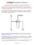
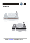
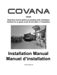
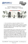
Installing a Hot-Spark Electronic Ignition Kit in a BOSCH distributor
NOTE:
Reversing the red and black ignition wires will destroy the ignition module and void the warranty.
The Hot-Spark module’s red wire connects to positive ( + or 15 on Bosch coil). The black wire connects
to negative ( - or 1 on Bosch coil). Remove the condenser and its wire from vehicle. Connect any other
wires to the coil in their original positions. This module is requires a 12V negative ground electrical
system.
Make sure that the ignition wires have plenty of slack inside the distributor and are not rubbing on any
moving parts. If you need to extend the length of the ignition wires, use 18- or 20-gauge (AWG) wire.
Crimp tightly or solder all connections.
Note: Always make sure that engine oil level is on the full mark before revving the engine
1
Prior to install: After removal of the breaker points, clean the distributor’s breaker points plate
thoroughly, so that the ignition module’s base plate makes good thermal contact with the distributor.
Coil to use: Stock Bosch coil or HS15HEC high-energy coil OK. Coil should have 1.5 Ohms or more
primary resistance. To measure primary resistance: Label and remove all wires to coil. Using a common
digital multimeter in the 200 Ω mode, measure between coil’s + and - terminals. Allow a few seconds for
the reading to settle downward, until it stabilizes. Subtract about 0.3 Ohms from the reading to
compensate for multimeter’s inherent resistance.
For best performance, the coil should also have a minimum of 7,000 Ohms secondary resistance
(measured from coil’s + or – terminal to center high tension terminal, in the 20K Ω mode of the
Ohmmeter). Note: Do not use a low-resistance coil, such as the MSD or Accel coil - they don’t have
enough primary resistance for this application. Using a coil with too little primary resistance can cause the
ignition module to overheat and fail, thus voiding the warranty.
Test Maximum Charging System Voltage: If the charging system voltage, measured at the coil’s
positive terminal, is more than 14.2 volts at 2,500+ RPM, the voltage regulator likely needs replacing.
Too much voltage can damage the ignition module and other electronic components.
Air Gap between Magnet Sleeve and Ignition Sensor: The air gap should be approximately 0.8 mm
(.030 in.), although exact gap is not critical. There should be sufficient gap to prevent the magnet sleeve
from rubbing against the Hot-Spark sensor. If there's not a wide enough gap between the magnet sleeve
and the ignition sensor, you can on some kits adjust the distance. On the kits that do not have this option,
you can hold ignition base plate towards the position it needs to be maoved while tightening the set screw.
If this is not enough you can try the following: With the ignition module fastened to the distributor's
breaker plate, bend the top, red part of the ignition module away from the magnet sleeve slightly, to
widen the gap a little. Don't pry against the plastic magnet sleeve - it may break. Note: when making
adjustemts: do not over-tighten these nuts – apply no more than 5 ft. lbs. of torque! Use a nut driver, not a
socket wrench.
Ignition Timing: Set the ignition timing, with a stroboscopic light, to the distributor’s factory
specification. The difference in distributor position with points vs. electronic ignition can be as much as
30 degrees or so clockwise or counterclockwise, so you’ll definitely have to reset the timing.
Example of Hot-Spark kit in a Bosch 009 non-vacuum-advance distributor
2
1. Turn off the ignition switch and/or remove the ground strap from the battery. Though not absolutely
necessary, it is probably easiest overall to remove the distributor from the car before installing the HotSpark module. If the contacts in the inside of the distributor cap are worn or damaged, replace the
distributor cap. Replace the rotor if it’s worn.
2. Remove distributor cap, leaving the plug wires in place, unless replacing the distributor cap as well.
3. Remove points, condenser and the condenser’s wire from the vehicle. If there is a wire that used to go
to the condenser, tape it off, as it will no longer be used. Because the Hot-Spark kit does not modify the
distributor, the points and condenser can be reinstalled at a later time.
4. Install the screws that attached the condenser and its grommet back into their holes. If the screws are
now too long, use a washer or two on the screws.
5. Clean any grease or dirt thoroughly from the distributor’s points cam and the breaker points plate.
6. Insert the Hot-Spark module’s wires, one at a time, from the inside of the distributor out, through the
hole in the side of the distributor. You can use a narrow, flat-bladed screwdriver to gently push the edges
of the grommet from the inside of the distributor. Gently pull and rock, up-and-down and side-to-side, the
rubber grommet, halfway through the hole, until it seats.
7. Apply a very thin coat of the included thermal transfer grease to the bottom of the ignition base plate.
Place the Hot-Spark module’s bottom plate onto the distributor’s breaker plate. The peg should fit snugly
into the hole in the breaker plate and the screw holes should line up. The Hot-Spark module’s base plate
should lie flat and snug on the distributor’s breaker plate. Insert the screw and tighten.
8. Check to see if the vacuum advance is working properly by sucking on the vacuum canister port. The
breaker plate should move smoothly and freely.
9. Press the magnet sleeve down on the rotor shaft. Next install the rotor on top of the magnet sleeve. The
rotor should slide all the way down and lock into place, so that it cannot turn independently of the
distributor shaft. If you can still turn the rotor independently of the distributor shaft, the magnet sleeve is
not seated all the way down. Be sure that the indentations inside the magnet sleeve line up with the lobes
of the distributor cam - turn the magnet sleeve on the distributor shaft until you can feel it line up.
10. Adjust the two Hot-Spark ignition wires so that they have plenty of slack inside the distributor and
they’re not rubbing on any moving parts.
11. Install the distributor cap and reinstall the distributor. Be sure that the anti-chatter spring is in place in
the distributor drive gear in the bottom of the distributor shaft hole.
12. The Hot-Spark module’s red wire connects to positive ( + or 15 on Bosch coil). The black wire
connects to negative ( - or 1 on Bosch coil). DO NOT reverse the polarity of these wires or the ignition
module will be destroyed.
13. Check all wire connections, including the two Hot-Spark wires and the spark plug and coil hightension wires. If you need to extend the length of the wires, use 18- or 20-gauge wire. We recommend
soldering all splices and connections, if you can, or crimp all connections tightly. Make doubly sure that
all wires are connected to the proper terminals, etc. before reconnecting the battery or turning the ignition
switch to the ON position. Make sure that all connectors are snug.
3
Timing:
You can set the timing statically to about 0° (TDC) at first, so that the engine will start. Start the engine
and tweak the timing until the engine runs by itself. Time the engine with a stroboscopic light in the
normal manner. Although the initial timing can be set roughly, final timing settings need to be set using a
stroboscopic timing light. This will probably be the last time you have to set the timing for a long time, so
it’s worth it to spend the extra time and effort to set the timing absolutely spot-on accurately. An engine
with its timing set to perfection will start with the slightest bump of the starter and purr like a kitten at idle
– something to make you feel good every time you start the engine.
Setting timing on VW’s:
TDC = Top Dead Center, or 0° BTDC = Before Top Dead Center ATDC = After Top Dead Center
It’s hard to say which distributor an old air-cooled VW actually has in place. The original stock
distributor could very well have been replaced with a different distributor over the years. Bosch
distributors for VW have a Bosch number stamped on their side similar to 0 231 xxx xxx. Distributors
may also have a VW number, which is preceded by a VW (and maybe an Audi) symbol. It’s most useful
to find the Bosch number and look up the timing specifications for that particular VW distributor here on
http://www.oldvolkshome.com/ignition.htm
Finding Timing Marks on Type I VW Engine (Beetle, Ghia, Thing, pre-1972 Bus, etc.): There are
several different versions of stock crankshaft pulleys that came with Type I VW engines over the years,
each having its own set of notches (timing marks) in different places relative to TDC - very confusing.
Like the distributor, the pulley may have been swapped out several times over the years, so you don’t
know what the notches on it mean. It’s possible to find TDC and other degree positions on a “mystery”
VW pulley - it’s a tedious process, though.
It’s much easier to replace an old Type I VW engine’s “mystery” crankshaft pulley with an aftermarket
aluminum pulley of stock diameter, with degree markings etched on it. Not only does it make setting the
timing much easier; it’s also handy for checking valve clearance, etc.
Warning: Using an aftermarket pulley of smaller than stock diameter causes slower spinning of the
engine’s squirrel-cage fan, reducing the volume of air cooling the engine, possibly resulting in
overheating and premature engine failure. These smaller-diameter pulleys are often marketed as “HiPerformance” or “Power” pulleys. They are okay for racing use, where the engine is always run at high
RPM levels. For daily driving, we recommend a stock-sized pulley for better engine cooling.
Timing the Bosch 009 or 050 Centrifugal-Advance Distributor (VW or Porsche only): Use a
stroboscopic timing light and tach/dwell meter or tachometer, regardless of whether the distributor is
equipped with points or an electronic ignition module. Static timing at around 0° (TDC) is suitable only
for the initial adjustment, in order to get the engine running. To set the timing accurately, you must use a
stroboscopic light connected to No. 1 cylinder’s spark plug wire. Set the timing with the engine running at
3,200+ RPM, so that the timing is fully advanced. The 009’s timing should be set no further advanced
than 30° BTDC at 3,200+ RPM.
You can locate the 30° BTDC spot on a stock VW Type I crankshaft pulley, which has a 175 mm (6-7/8
in.) diameter, by measuring, clockwise, from top dead center, around the circumference of the pulley,
45.8 mm, or 1-13/16 in. Make a small white paint mark there. That’s about 30° BTDC.
Timing a Stock, Air-Cooled VW Vacuum-advance Distributor: A stock, vacuum-advance distributor
should be timed with a stroboscopic light and tach/dwell meter, according to the specifications in the VW
service manual.
4
For dual vacuum-advance distributors (with vacuum canisters having two vacuum ports): You can locate
the 5° ATDC spot on a stock VW Type I crankshaft pulley, which has a 175 mm (6-7/8 in.) diameter, by
measuring, counterclockwise, from TDC, around the circumference of the pulley, 7.6 mm (5/16 in.). Paint
a small white mark here. This is about 5o ATDC, the point at which the dual vacuum-advance distributor
(its vacuum canister has two vacuum ports) is usually timed at idle. Refer to the official VW Service
Manual for the proper timing specifications for the distributor used in your vehicle.
For SVDA (single vacuum, dual advance) distributors: You can locate the 7.5° BTDC spot on a stock
VW Type I crankshaft pulley, which has a 175 mm (6.895 in.) diameter, by measuring, clockwise (to the
right), from TDC, around the circumference of the pulley, 11.45 mm (7/16 in.). Paint a small white mark
here. This is the point at which the centrifugal advance (009) and certain single-vacuum, dual-advance
(SVDA) distributors (their vacuum canister has only one vacuum port) are timed at idle. Again, refer to
the official VW Service Manual for the proper timing specifications for the distributor used in your
vehicle.
Volvo-PENTA Marine engines with Bosch distributor
Make sure that there's enough space between the ignition sensor and the magnet sleeve. Sometimes, the
screw that attaches the distributor cap clip to the distributor body protrudes too far into the distributor,
crowding the ignition module too close to the magnet sleeve. You’ll probably have to add one or two
extra washers to the distributor cap clip screw, to keep the screw from sticking too far into the distributor.
Then, loosen the set screw that holds the ignition module base plate. Hold the ignition base plate away
from the magnet sleeve slightly, while retightening the ignition module set screw. There should be a gap
of about 0.8mm (.030 in.) between the magnet sleeve and the ignition module, although the exact gap is
not critical. To increase air gap slightly, hold ignition base plate away from distributor shaft while
tightening set screw.
The Volvo-Penta distributor uses an 8mm (5/16”) O.D. round rubber grommet. You’ll have to cut the
spade connectors off the two ignition wires. Pass the wires, from the inside of the distributor out, through
the round hole in the side of the distributor body and then through the round rubber grommet. Seat the
grommet in the hole. Crimp or solder new ¼” (6.37mm) female quick-connect terminal connectors onto
the ends of the wires.
Typically, a purple wire goes to the condenser on the Volvo-Penta distributor. When installing the HotSpark ignition, remove the points and condenser and tape off the purple wire, as it will no longer be used.
5
Cleaning, lubricating and checking:
Lubricating: You likely won’t have the distributor out of the engine again for some time. So now is a
good time to lubricate under the vacuum advance plate, the distributor shaft and its bushing and the
swinging centrifugal advance weights in the bottom of the distributor. You can access the centrifugal
advance weights easily by removing the curved plug on the outside of the distributor, near the bottom. A
somewhat sharp, flat-bladed putty knife is handy for prying off this plug. A small amount of heavy oil,
such as 90W hypoid, synthetic heavy transmission oil or heavy motor oil works well for lubricating the
distributor. Don’t use a thin solvent, such as WD-40, for lubrication, as its lubricating qualities won’t last
for long. Apply a few drops of oil to the felt wick under the rotor. Clean up any excess oil or grease.
Vacuum canister check: If your engine uses a vacuum-advance distributor, test the vacuum canister by
sucking hard on its vacuum port. The vacuum advance plate, under the points, should move
counterclockwise and clockwise noticeably and freely when you do this repeatedly. If you suck and then
cover the vacuum port with your tongue, the vacuum advance plate should stay in the same position until
you lift your tongue. If it drifts back before you lift your tongue, the diaphragm is leaking and it won’t
advance the timing properly. In that case you need to replace the vacuum canister or the entire distributor.
If the distributor is dirty and covered with gunk inside and out, you may need to soak it in a solvent such
as naphtha or kerosene (don’t allow solvent to leak into the vacuum canister - remove the vacuum canister
first). After soaking and scrubbing with a stiff nylon brush, rinse thoroughly with clean solvent, dry with
compressed air or allow to air-dry and lubricate the shaft, bushing, advance weights and breaker advance
plate. Wipe up excess grease and oil. If the vacuum advance plate still doesn’t move freely, you may need
to replace the vacuum canister or replace the distributor.
Testing the Coil’s Spark: Begin with a fully charged battery. Disconnect the high-tension cable from the
center terminal of the distributor cap. Hold it about 10 mm (3/8”) from the engine crankcase. (Be sure that
you’re very well insulated from the end of the high-tension cable or many thousands of volts could course
through your body!) Have a helper crank the engine while you watch the spark produced. A weak coil
will produce an anemic yellowish or orange spark; it might fire only when the cable is moved close to the
crankcase or it won’t fire at all. A healthy coil will produce a bright bluish-white spark with a loud,
distinct CRACK! sound. If your coil doesn’t produce a strong, whitish-bluish spark, you should replace it.
Distributor Cap and Rotor: Stock rotors and distributor caps work fine with the Hot-Spark module. A
worn, corroded or scored distributor cap and/or rotor is often the cause of the timing jumping around
erratically at idle. With the Hot-Spark electronic ignition installed in place of points, several times as
much voltage surges through the rotor to the distributor cap terminal contacts. While the rotor and
distributor cap may have functioned alright with points, the increased strain of double the voltage may be
too much for the old, worn rotor and distributor cap. We recommend installing a new distributor cap and
rotor when converting from points to electronic ignition.
Spark Plug Gap: With the Hot-Spark ignition kit, the stock spark plug gap specification is fine. For
racing purposes, you can increase the spark plug gap by about .005 inches, or .12 mm. Be aware that
changing the spark plug gap can affect the timing - you should recheck the ignition timing if you change
the spark plug gap.
6
Using Hot-Spark Ignition with MSD Blaster:
Refer to this diagram to use the Hot-Spark Ignition with the MSD (Multiple Spark Discharge) Blaster:
Hot-Spark Ignition and MSD 6 Series Wiring Diagram:
7
Volvo 1800 with tachometer:
Refer to this diagram to use the Hot-Spark Ignition with the Volvo 1800 Tachometer:
8
Limited Warranty: Hot-Spark Ignition Products warrants its electronic ignition conversion kits to be free from
defects in material and workmanship under normal use and if properly installed for a period of three years from date
of purchase. If found to be defective as mentioned above, it will be replaced or repaired if returned prepaid along
with proof of date of purchase. Warranty shall be null and void if it is determined that said electronic ignition
conversion kit has been connected improperly, if it is used with an ignition coil which has insufficient resistance in
its primary circuit or if the polarity of the electrical wiring of the ignition kit has been reversed.
This shall constitute the sole remedy of the purchaser and the sole liability of Hot-Spark Ignition Products. To the
extent permitted by law, the foregoing is exclusive and in lieu of all other warranties or representations whether
expressed or implied, including any implied warranty of merchantability or fitness. In no event shall Hot-Spark
Ignition Products be liable for special or consequential damages.
www.Hot-Spark.eu
© 2007 Hot-SparkTM Ignition Products
9