1
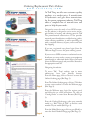
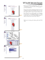
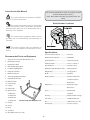
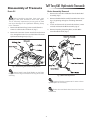
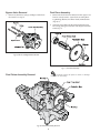
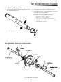
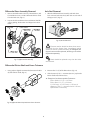
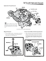
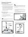
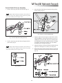
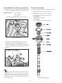
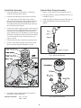
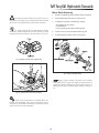
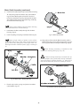
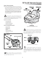
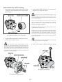
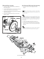
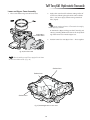
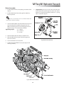
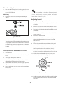
T a b l e
o f
C o n t e n t s
Ordering Replacement Parts Online.................................ii
Adjusting Neutral ....................................................................36
Icons Used in this Manual .....................................................iv
Axle Shafts and Differential Gear Assembly ..................30
Recommended Tools and Equipment .............................iv
Before Starting Assembly .....................................................18
Serial Number Locations .......................................................iv
Bleeding Air from Hydrostate Oil Circuit .........................36
Specifications: ...........................................................................iv
Brake Assembly ........................................................................35
Disassembly of Transaxle ..........................1
Bypass Shaft Assembly ..........................................................18
Axel Shafts and Differential Gear Assemblies ...............7
Center Case Assembly ...........................................................27
Axle Seal Removal ...................................................................8
Cylinder Block (Pump) Assembly .......................................24
Axle Shaft and Bushing Tolerances ...................................7
Differential Gear Assembly ..................................................30
Brake Assembly Removal......................................................1
Lower and Upper Case Assembly ......................................33
Bypass Valve Removal ...........................................................4
Motor Shaft/Center Case Assembly ..................................28
“C” Arm Removal .....................................................................3
Motor Shaft Assembly ...........................................................25
Center Case & Motor Shaft Ass’y Removal......................9
Oil Change Frequency ...........................................................37
Center Case Removal .............................................................10
Oil Requirement .......................................................................37
Cylinder Block (Motor) Assembly Removal ....................10
Final Pinon Shaft Assembly .................................................32
Cylinder Block Assembly (Pump) Removal .....................12
Post Assembly Procedures ...................................................36
Differential Gear Assembly Removal ................................8
Pump Shaft Assembly ............................................................22
Differential Gear Assembly Removal ................................5
Swash Plate Assembly............................................................24
Differential Pinion Shaft and Gear Tolerance ................8
Troubleshooting and Diagnosis Guides....38
Drain Oil ......................................................................................1
Filter Removal ...........................................................................3
Final Pinion Shaft and Bushing Tolerances ....................5
Final Pinon Assembly .............................................................4
Final Pinon Assembly Removal...........................................4
Fulcrum Removal .....................................................................14
Hydraulic Flow Diagram........................................................17
Hydrostatic Pump Removal .................................................9
Levers (Shafts) and Linkage Removal...............................16
Lower Case Removal ..............................................................3
Magnet Removal .....................................................................9
Motor Housing Removal .......................................................10
Motor Shaft Removal .............................................................11
Pump Shaft Removal ..............................................................15
Shock Absorber and Control Arms Removal .................2
Swash Plate Removal..............................................................13
Assembly of Transaxle ...............................18
i
Ordering Replacement Parts Online
w w w . t u f f t o r q . c o m
At Tuff Torq, we offer our customers quality
products at a modest price. A manufacturer
of hydrostatic and gear drive transmissions
for the power equipment industry, Tuff Torq
offers a complete line of transmissions and
parts to help fit your needs.
Designed to meet the needs of our OEM customers, this website is designed to assist service and repair facilities in locating and ordering parts for Tuff
Torq manufactured transmissions. It also provides
transaxle parts identification, troubleshooting guides,
online ordering capabilities, as well as providing you
with a complete inventory of parts, service and same
day shipping.
Home
If you are a registered user, please login (from the
Welcome Page) to access the parts ordering system.
If you are not a OEM customer or authorized service
distributor, you may need to contact your equipment
manufacturer or authorized dealer. Select your brand
(from the Welcome page) and you will be directed to
the appropriate web site.
Page 1
Navigating the website:
To access Tuff Torq’s website, type in www.
tufftorq.com from your Internet browser.
From the Home page, click on “Service” to enter the
Online Ordering page (Ref. Page 1)
From The Online Ordering page, click on “Click here
to enter service website” to enter the Welcome page
(Ref. Page 2).
Page 2
From the Welcome page, login (for register users)
and follow the on screen instructions. Or, click on
“Catalog/Order” to enter Store Browser (Ref. Page
3).
From the Catalog/Order page, select your transaxle
model, e.g., K61. Click on “K61” to find the serial
number for your model (Ref. Page 4).
From the Model Series page, click on, your Model to
enter the Serial Number Range page (Ref. Page 5).
Page 3
ii
Tuff Torq K61 Hydrostatic Transaxle
Having your Model, and Model Series, click on the
serial number to enter the Online Ordering page for
you Transaxle (Ref. 6).
Navigate through the exploded parts illustration until
the desired part has been identified. Take note of the
part’s figure number. Locate the part number in the
parts listing. You can add the part to your shopping
cart and return to the exploded illustration or—click
on the item to go to the Product Explorer page for
additional detail about the part (Ref. Page 7).
Page 4
Thank you for visiting and ordering online with Tuff
Torq.
Page 5
Page 6
Page 7
iii
Icons Used in this Manual
This manual is applicable for repair of all (9) K61 models
built and distributed by Tuff Torq.
K61C, K61D, K61E, K61F, K61I, K61J, K61M, K61N, and
K61O
This symbol identifies the presents of IMPORTANT, if not critical, information.
Serial Number Locations
This symbol is intended to alert you of important
technical information and/or maintenance procedures
which will better assist you in the disassembly and reassembly of the Transaxle.
This symbol offers suggestions which will better assist you in the disassembly and reassembly of
Transaxle.
This symbol indicates when an application of
grease or oil is to be applied to the part prior to its assembly.
Specifications:
Transaxle Torque output .......................217 Ft. lbs.
Recommended Tools and Equipment
Maximum Input Speed ..........................3000 RPM
1.
Transaxle Service Stand (Part Number 1111)
2.
Black Electrical Tape
3.
Needle Nose Pliers
4.
O.D. Retaining Ring Pliers
Axle Shaft Size ...........................................25.4 mm (1.0 in.)
5.
I.D. Retaining Ring Pliers
Maximum Static Weight on Axle ........265 kg (584 lbs.)
6.
Neoprene Hammer
Weight (Dry) ...............................................17.5 kg (38 lbs.)
7.
Ball Peen Hammer
Brake .............................................................Dry Band
8.
Telescoping Magnetic Pickup
Brake Capacity ...........................................390 N-m (288 ft. lbs.)
9.
Flathead Screw Driver
Input Shaft Size .........................................14.85 mm (0.58 in.)
Reduction Ratio ........................................18.79 : 1 or 26.97 : 1
.........................................................................at 245 N m (55 lbs.)
10. Roll Pin Punch
.........................................................................Brake Force
11. Feeler Gauge
Differential ..................................................Automotive Type
12. Calipers
13. Putty Knife
.........................................................................Bevel Gears
14. Wrench (size):
Gears .............................................................Heat-Treated
8 millimeter
Automatic Neutral Return .....................Standard
12 millimeter
Housing........................................................Aluminum Die Castings
14 millimeter
17 millimeter
Tow Value ....................................................Std. (Brake Release)
Service Stand (Part Number 1111)
Oil ...................................................................10W 30 Class CC or CD
15. Sealant
Oil Capacity ................................................3.3 liters (3.5 qts.)
16. Grease
17. Filter
18. Seal Kit (s)
19. Oil (10W 30 Class CC or CD)
iv
Disassembly of Transaxle
Tuff Torq K61 Hydrostatic Transaxle
Drain Oil
Brake Assembly Removal
Before beginning tear-down clean work area
thoroughly and cover workbench with clean paper.
This is extremely important as just one grain of sand
can cause damage to the Hydrostatic Rotating Group
in the Transaxle.
1.
Remove the Oil Drain Plug (12 mm wrench) from the
Lower Case of Transaxle and drain oil. (Fig. 1)
2.
Remove the Connector (14 mm wrench) from the Center
Case, through the Lower Case and drain the oil from the
Hydrostatic Rotating Groups. (Fig. 1)
1.
Remove the Cotter Pin and Washer from the Brake Rod
Assembly. (Fig. 2)
2.
Remove the Brake Rod Assembly from Brake Arm B (see
Fig. 3) by pivoting 90 degrees and sliding downward.
(Fig. 2)
3.
Loosen and remove the (3) 8 mm bolts/washers (12mm
wrench) and detach the Brake Assembly. (Fig. 2)
4.
Remove Snap Ring (Snap Ring Pliers) and the Brake
Drum from Brake Shaft. (Fig. 2)
Fig. 1, Oil Drain Plug and Pressure Fill Plug removal
Always install a new Seal Washer on the Drain
Plug and new O-rings on Pressure Fill Plug when reassembling.
Fig. 2, Brake Assembly Removal
Inspect all brake components for wear or damage. Replace as necessary.
Brake drum and brake band are to be free from
oil and dust.
1
Shock Absorber and Control Arms Removal
(On K61 Models where applicable)
1.
Remove the Shock Absorber. (Fig. 3)
2.
Remove the Roll Pin and the H-Control Arm from the
Control Shaft. (Fig. 4)
3.
Remove the Roll Pin and the Brake Arm from the Brake
Shaft. (Fig. 4)
4.
Remove the Roll Pin and Brake Arm “B” from Brake Arm
“A”. (Fig. 4)
5.
Remove the Roll Pin and the (Tow) Release Valve Arm
from the Bypass Shaft. (Fig. 4)
Fig. 4, Arms and Roll Pins
Fig. 3, Levers and Arms Removal
2
Tuff Torq K61 Hydrostatic Transaxle
Lower Case Removal
Filter Removal
1.
1.
Place the Transaxle on a Service Stand in the serviceable
position (Lower Case up), to keep it steady during teardown. (See “Recommended Tools and Equipment”).
Remove the Filter from the Center Case and discard.
(Fig. 7)
Service Stand (Part Number 1111) can be ordered online or through your local Tuff Torq distribitor.
See page iv, “Recommended Tools and Equipment.”
2.
Remove the (14) bolts (8 mm) securing the Transaxle’s
Upper and Lower Cases. Lift the Lower Case away from
the Upper Case, exposing the internal parts.
(Fig. 5)
Fig. 7, Filter Removal
Install a new filter any time case halves are
separated.
Fig. 5, Upper and Lower Housing Removal
“C” Arm Removal
1.
If separation does not occur easily, a screwdriver can be inserted at any of the (4) pry points (indicated by the black arrows) (Fig. 6)
Disconnect “C” Arm from the Bypass Shaft by applying
slight sideward pressure to the spring loaded Push Pins.
This will keep them from springing out. With the Push
Pins secure, lift the “C” Arm off the Push Valve Bypass
Shaft. (Fig. 8, 9)
Fig. 6, Pry Points
Fig. 8, “C” Arm Removal
Care should be taken not to damage the Housing Sealing lips while prying apart. Remove any old
sealant residue from both case halves.
3
Bypass Valve Removal
Final Pinon Assembly
1.
1.
Remove the Final Pinion Assembly from the Upper Case
from its seated position. Separate the assembly, Bearing, Bushing, Washer, Final Pinon Shaft, and Reduction.
(Fig. 10, 11)
2.
Inspect the Final Pinion Shaft and the Reduction Gear
for scoring, pitting, discoloration and chipped or broken
teeth. (Fig. 11)
Remove (2) Push Pins, Springs, and Bypass Valve from
the Center Case. (Fig. 9)
Fig. 9, Push Pin and Bypass Valve Removal
Fig. 11, Final Pinion Assembly
Final Pinion Assembly Removal
Carefully inspect all parts for wear or damage.
Replace as necessary.
Fig 10, Final Pinon Assembly Removal
4
Tuff Torq K61 Hydrostatic Transaxle
Final Pinion Shaft and Bushing Tolerances
1.
Using calipers (digital recommended) measure the O. D.
(X) of the Final Pinion Shaft. (Fig. 12)
2.
Measure the I. D. (Y) of the “loose” Bushing. (Fig. 12)
3.
If the clearance (Y-X) is > 0.50 mm (.019 in), replace the
Final Pinion Shaft and/or Bushing.
◆ Example of an Acceptable Tolerance:
Pinion Shaft O. D. (X) = 14.79 mm
Bushing I. D. (Y) = 15.27 mm
Y (15.27 mm) - X (14.79 mm) = 0.48 mm of
clearance.
◆ Example of an Unacceptable Tolerance:
Pinion Shaft O. D. (X) = 14.75 mm
Bushing I. D. (Y) = 15.29 mm
Y (15.29 mm) - X (14.75 mm) = 0.54 mm of
clearance. This is > the wear limit of 0.50
mm, replacement is necessary.
Fig. 12, Final Pinion Shaft and “Loose” Bushing Clearance
Differential Gear Assembly Removal
Fig 13, Differential Gear Assembly and Axle Removal
5
Differential Gear Assembly Removal (continued)
Fig 14, Differential Gear Assembly and Axle Removal
1.
Remove Thrust Washer from either the Left or Right Axle.
(Fig. 14, 16)
2.
After removing the Thrust Washer, rotate the Axle until
the open end of C-Ring is facing downward. Holding the
Differential Side Gear stationary, slightly slide the Axle
outward exposing the C-Ring. Using a Telescoping Magnet, remove C-Ring. (Fig. 14, 16)
3.
Repeat steps 1 and 2 for opposing shaft.
4.
With the Thrust Washers and C-Rings removed, hold
the Gear Assembly in place. Carefully back out both
Axle Shafts until the shafts splines clear the Side Gears.
Remove the Gear Assembly and inspect components for
wear or damage. (Fig. 15)
Rotating the Axle until open end of C-Ring is
facing downward will prevent C-Ring from dropping into
Upper Case.
5.
Carefully back out and remove the Left and Right Axle
Shafts. (Fig. 14, 16)
6.
Remove (2) “loose” Bushings from the Upper Case.
(Fig. 16)
Inspect the Axle Shafts and Bushings for scoring, pitting, discoloration, damaged ring grooves, and
chipped or broken splines. Replace as necessary.
6
Tuff Torq K61 Hydrostatic Transaxle
Axle Shaft and Bushing Tolerances
1.
Using calipers (digital recommended) measure the O. D.
(X) of the Axle Shaft. (Fig. 15)
2.
Measure the I. D. (Y) of the “Loose” Bushing. (Fig. 15)
3.
If the clearance (Y-X) is > 0.35 mm (0.014 in), replace the
Axle Shaft and/or “loose” Bushing.
◆ Example of an Unacceptable Tolerance:
Axle Shaft O. D. (X) = 18.89 mm
Bushing I. D. (Y) = 19.25 mm
Y (19.25 mm) - X (18.89 mm) = 0.36 mm of
clearance. This is > the wear limit of 0.35 mm,
replacement is necessary.
Fig. 15, Axle Shaft and “Loose” Bushing Clearance
Axel Shafts and Differential Gear Assemblies
Fig. 16, Differential Gear and Axles
7
Differential Gear Assembly Removal
Axle Seal Removal
1.
Remove the Differential Side Gears, Thrust Washers, Differential Pinion Gears, and the Differential Pinion Shaft
from the Final Gear. (Fig. 17)
1.
2.
Inspect the Side and Pinion Gears and Pinion Shaft for
scoring, pitting, discoloration and chipped or broken
teeth.
After the Differential Gear Assembly and Axles have
been removed, take out the (2) Axle Seals at each end of
the Upper Case. (Fig. 19)
Fig. 19, Axle Seal Removal
Extreme caution should be taken when removing Seals from the Upper Case. Immediately behind
each Axle Seal is a press-fit bushing. If damaged, the
Upper Case must be replaced, bushings can not be
replaced separately.
Fig. 17, Differential Gear Assembly
Seals should be replaced every time the Axles
are removed.
Differential Pinion Shaft and Gears Tolerance
1.
Using calipers (digital recommended) measure the O. D.
(X) of the Pinion Shaft. (Fig. 18)
2.
Measure the I. D. (Y) of the Pinion Gears. (Fig. 18)
3.
If the clearance (Y-X) is > 0.50 mm (0.019 in), replace the
Pinion Shaft and/or Pinion Gears.
◆ Example of an Unacceptable Tolerance:
Pinion Shaft O. D. (X) = 14.75 mm
Pinion Gear I. D. (Y) = 15.30 mm
Y (15.30 mm) - X (14.75 mm) = 0.55 mm of
clearance. This is > the wear limit of 0.50 mm,
replacement is necessary.
Fig. 18, Differential Pinion Shaft and Pinion Gears Clearance
8
Tuff Torq K61 Hydrostatic Transaxle
Hydrostatic Pump Removal
Slide the Brake Drum onto the
Motor Shaft to provide a means of griping and lifting the Center Case and Motor Shaft Assemblies from the Upper
Case.
Fig. 20, Center Case and Motor Shaft Assemblies
Magnet Removal
Center Case & Motor Shaft Ass’y Removal
1.
2.
Loosen (3) Bolts (10 mm) — removing one, on the Center Case; remove the Magnet. Clean the Magnet thoroughly before reassembling. (Fig. 21)
After removing the remaining two bolts holding the
Center Case to the Upper Case, place one hand over
the Motor Housing and the other hand over the Center Case. While compressing both portions together
slightly, lift the entire assembly from the Upper Case.
(Fig. 22)
Fig. 21, Magnet Removal
Fig. 22, Center Case and Motor Shaft Assemblies
9
Hydrostatic Pump Removal (continued)
Center Case Removal
Cylinder Block (Motor) Assembly Removal
3.
4.
Remove the Cylinder Block Assembly from the Motor
Shaft. (Fig. 25)
5.
Inspect each component of the Cylinder Block Assembly
for burrs, scoring, pitting, discoloration, distortion, and
wear.
While still maintaining pressure on the Cylinder Block
Assembly and the Motor Housing, carefully separate the
Center Case from the Motor Shaft Assembly. (Fig. 23)
Fig. 25, Cylinder Block Assembly
Fig. 23, Center Case and Motor Shaft Assembly
If any of the components of Cylinder Block Assembly are damaged, they must be replaced with a
complete Cylinder Block Assembly. Individual components are not serviced separately.
During separation, be careful not to damage
contact surfaces of Center Case and Cylinder Blocks.
(Fig. 24)
Be careful that the Pistons do not fall out of
Cylinder Block. Do not set Cylinder Block down with
mating surface contacting table top, as this can cause
damage to the machined surfaces.
Fig. 24, Center Case and Cylinder Block, Machined Surfaces
Fig. 26, Finger placement during removal
Inspect the machined surfaces of the Center
Case. If excessive scratches are detected, replace the
Center Case and both Cylinder Block Assemblies, simultaneously.
To avoid the pistons from dropping out during
removal of the assembly, position fingers around the
Cylinder in order to apply pressure on each of the five
pistons. (Fig. 26)
10
Tuff Torq K61 Hydrostatic Transaxle
Hydrostatic Pump Removal (continued)
Motor Housing Removal
Motor Shaft Removal
6.
Remove the Spring and Snap Ring. Next, remove the
Thrust Bearing Set seated in the Motor Housing. (Fig. 27)
9.
7.
Inspect the press-fit Bushing in the Motor Housing for
burrs, scoring, pitting, discoloration, and wear. If damaged, replace the Motor Housing. press-fit Bushings are
not serviced separately.
8.
Withdraw the Motor Shaft from the Motor Housing. If
the Shaft doesn’t back out freely, check to see if Snap
Ring was removed, see step 6. (Fig. 29)
10. Remove the Snap Ring and Washer. Inspect the Washer
for wear or damage and replace if necessary.
(Fig. 29)
Remove the Snap Ring and Seal. Discard the Seal and
replace it with a new Seal during reassembly. (Fig. 27)
Fig. 29, Motor Shaft Removal
There is no need to remove the press-fit Bearing on the Motor Shaft, unless it is damaged or worn.
Fig. 27, Motor Shaft and Housing
Fig. 28, Motor Shaft Assembly
11
Hydrostatic Pump Removal (continued)
Cylinder Block Assembly (Pump) Removal
11. Remove the Cylinder Block Assembly from the Pump
Shaft. (Fig. 30)
To avoid the pistons from dropping out during
removal of the assembly, position fingers around the
Cylinder in order to apply even pressure to all five pistons. (Fig. 32)
Fig. 32, Finger Placement During Removal
During separation, be careful not to damage
contact surfaces of Center Case and Cylinder Blocks.
(Fig. 33)
Fig. 30, Cylinder Block Removal from Pump Shaft
12. Inspect each component of the Pump Cylinder Block Assembly for burrs, scoring, pitting, discoloration, distortion, and wear. (Fig. 31)
Fig. 31, Cylinder Block Removal
If any of the components of the Cylinder Block
Assembly are damaged, the complete assembly must
be replaced. Individual components are not serviced
separately.
Fig. 33, Center Case Machined Surfaces
Take care to insure that the Pistons do not fall
out of Cylinder Block. Do not set Cylinder Block down
with mating surface contacting table top, as this also
could cause damage.
Inspect the machined surfaces of the Center
Case. If excessive scratches are detected, replace the
Center Case and both Cylinder Block Assemblies, simultaneously. (Fig. 33)
12
Tuff Torq K61 Hydrostatic Transaxle
Swash Plate Removal
1.
6.
Before removing the Swash Plate Assembly measure the
clearance (using Feeler gauge) between edge of Swash
Plate’s Slot and the Shift Blocks. If the clearance (gap) is
> 0.15 mm (0.005 in), replace both Shift Blocks and the
Swash Plate Assembly, simultaneously. (Fig. 34)
Remove the (2) Thrust Metals (bearing pads) from the
Upper Case. (Fig. 36)
Fig. 36,Thrust Metal Bearing Removal
Inspect Thrust Bearing components for pitting,
scoring, discoloration, missing rollers, and roller retainer breakage.
Fig. 34, Shift Blocks Clearance Tolerance
2.
Remove the Spring and the Snap Ring. (Fig. 35)
Fig. 35, Swash Plate Removal
3.
Remove the Thrust Bearing seated in the Swash Plate.
(Fig. 36)
4.
Remove the Swash Plate. (Fig. 36)
5.
Inspect the press-fit Bushing in the Swash Plate for
burrs, scoring, pitting, discoloration, and wear. If damage, replace the Swash Plate. The press-fit Bushings are
not serviceable separately.
Fig. 37, Cylinder Block Assembly & Swash Plate
Do not attempt to remove the press-fit Bushing
in the Swash Plate. If damaged, replace Swash Plate
Assembly (press-fit Bushing is included in the assembly).
13
Swash Plate Removal (continued)
Fulcrum Removal
1.
Remove the Nut (17mm) and Washer from the Fulcrum
(Neutral Adjust Eccentric). (Fig. 40)
Fig. 38, Swash Plate’s Machined Ramps
Inspect the Swash Plate’s machined ramp surfaces and Press-Fit Bushings for scoring, pitting, discoloration, and wear. If the Swash Plate and/or Bushings are damaged, they must be replaced as a group.
7.
Fig. 40, Fulcrum Removal, from top of Upper Case
Using calipers (digital recommended) measure the
thickness of both Thrust Metals for wear. If the clearance is < 1.30 mm (0.051 in), replace Thrust Metals as a
set. (Fig. 39)
2.
Return the Upper Case to its service position (Flange
side up) and remove the Fulcrum. (Fig. 41)
3.
Inspect the Fulcrum Cam for wear or damage, replace if
required.
4.
Remove and discard (2) O-rings and replace with a fresh
pair. (Fig. 41)
Fig. 39,Thrust Metals Tolerance
Fig. 41, Fulcrum
Always replace the Thrust Metals worn beyond
wear limits as a group.
14
Tuff Torq K61 Hydrostatic Transaxle
Pump Shaft Removal
1.
Remove the Seal and discard. Replace with new a Seal
during reassembly. (Fig. 42)
2.
Remove the large internal Snap Ring and lift the Pump
Shaft from the Upper Case. (Fig. 43)
Inspect the Shaft and its components for scoring, pitting, discoloration, and other wear. Replace if
damage or worn. Inspect the Pump Shaft splines for
chipped or broken teeth.
Fig. 42, Pump Shaft Seal Removal
Fig. 43, Pump Shaft
Do not attempt to remove the press-fit Bearing
on the Pump Shaft unless it is damage or worn. Removal could result in damage to the Bearing.
15
Levers (Shafts) and Linkage Removal (If Applicable)
1.
Remove the Control Shaft Assembly.
2.
Remove the Fulcrum. Refer to page 14 for more details.
3.
Disconnect Snap Pin from the Brake Rod (see arrow ➊)
and remove Washer. (Fig. 44)
4.
Disengage the Brake Rod from Brake Arm “A” (see arrow
➋) and remove the Brake Rod. (Fig. 44)
5.
Remove Brake Arm “A.” (Fig. 44)
6.
Disengage the Brake Return Spring from the Brake Shaft
and the Upper Case, remove the Spring after steps 8 and
9.
7.
Disengage the Bypass Rod from the slot on the Brake
Shaft. Remove the Bypass Rod. (Fig. 45)
8.
Remove the Brake Shaft. (Fig. 45)
9.
Remove the Bypass Shaft and Spring. (Fig. 45)
Fig. 45, Bypass Shaft and Spring
Inspect all Levers and Linkage for scoring, pitting, discoloration, or any other visual damaged. Replace as necessary.
Remove and discard O-rings on Shafts. Replace
with new O-rings before reassembly. Refer to the Assembly section for further information.
The Torsion Spring, shown here disassembled for clarity
only, should be handled (removing and installing) as a single item. For assembly refer to “ Control Shaft & Fulcrum
Assembly,” on page 21.
Fig. 44, Levers and Linkage Removal
16
Tuff Torq K61 Hydrostatic Transaxle
Hydraulic Flow Diagram
17
Assembly of Transaxle
Before Starting Assembly
Before starting the assembly of the Transaxle check all parts
to ensure that they are clean and free of any foreign
debris, this includes your work area and tools.
Rather than lubricating packing items (O-rings
and Seals) in advance, apply a light coating of grease
just prior to their installation. This will minimize the possibility of debris collecting of packing items while waiting to be installed.
Have on hand a new Seal Kit (19215499150). Check contents
of kit for possible defects before installation. Note that
the kit is designed to cover all K61 models. You may or
may not use all the items, in the kit, on your particular
model. The Seal Kit, as well as other parts necessary for
replacement, can be ordered on-line by visiting Tuff
Torq’s Web Site at: www.tufftorq.com (See “Ordering
Replacement Parts”, page ii).
5.
◆ From the reverse side of the Upper Case, mount the
Release Valve Arm onto the Bypass Shaft; then, align
and secure with Roll Pin. (Fig. 2)
Bypass Shaft Assembly
1.
Place the Upper Case on a service stand in the service
position (flange side up).
2.
Install a new O-ring onto the Bypass Shaft.
3.
Install the Spring onto the Bypass Shaft.
4.
Install the Spring and Bypass Shaft into the hole on the
Upper Case. (Fig. 1)
Since the Bypass Shaft is spring loaded it is recommended that the Release Valve (Tow) Arm be connected
before proceeding.
Apply a light coating of grease to the surface of
the O-ring. Also, apply a small amount of grease into
mating hole of Upper Case.
Fig. 2, Release Valve Arm Assembly
◆ Always install Roll Pins with the slit on a horizontal
plane. This will enable the pin greater holding ability.
Fig. 2a, Roll Pin Installation
Fig. 1, Bypass Shaft Assembly
18
Tuff Torq K61 Hydrostatic Transaxle
Interlock Linkage (If Applicable)
1.
Place the Upper Case back to the Service Position; then,
attach the Bypass Rod to the Bypass Shaft. (Fig. 3)
Fig. 5, Brake Shaft & Return Spring Assembly
Fig. 3, Bypass Rod Assembly
Brake Shaft Assembly (If Applicable)
1.
Install a new O-ring onto the Brake Shaft. (Fig. 4)
2.
Check Bushing for damage or exceptionable wear;
replace if necessary. (Fig. 4)
Fig. 6, Brake Shaft & Return Spring Assembly
Fig. 4, Brake Shaft Assembly
Apply a light coating of grease to the surface
of the new O-ring and Bushing. Also, apply a small
amount of grease into mating hole of the Upper Case.
3.
Align the Bypass Rod with the slot on the Brake Shaft.
(Fig. 5, 7)
4.
Place the Brake Return Spring under the Brake Shaft.
(Fig. 5, 7)
5.
Hook the Brake Return Spring to the Brake Shaft (see
arrow ➊); then, hook the opposite end of the spring to
the Upper Case housing (see arrow ➋). (Fig. 6)
Fig. 7, Brake Shaft—Bypass Rod Assembly
19
Brake Arm “A” Assembly
1.
Install a new O-ring onto the Brake Arm. (Fig. 8)
2.
Attach the Brake Rod to the Brake Arm; then, to the
Brake Shaft. (Fig. 8, 9)
4.
From the reverse side of the Upper Case, mount the
Brake Arm onto the Brake Shaft. The side of the Brake
Arm with the word “UP” should be visible; then, align
and secure with Roll Pin. (Fig. 10)
Apply a light coating of grease to the surface
of the new O-ring and Bushing. Also, apply a small
amount of grease into mating hole of Upper Case.
Fig. 10, Brake Arm Assembly
5.
Fig. 8, Brake Arm Assembly
3.
Mount the Brake Arm “B” onto the Brake Arm “A”; then,
align and secure with Roll Pin. (Fig. 11)
Secure the Brake Rod to the Brake Shaft with a Washer
and Cotter Pin. (Fig. 9)
Fig. 11, Brake Arm “B” Assembly
6.
Fig. 9, Brake Rod Assembly
With the Brake Linkage in place, seat the Brake
Shaft and the Brake Arm to their lowest position – In
order for the Roll Pin and the Brake Arm to align
properly (Fig. 10), the Return Spring must not hinder the full positioning of the Brake Shaft. Check
linkage for proper operation, adjust if necessary.
20
Place the Upper Case back to the Service Position and
continue with the assembly of Transaxle.
Tuff Torq K61 Hydrostatic Transaxle
Control Shaft & Fulcrum Assembly
1.
3.
Install a new O-ring onto the Control Shaft. (Fig. 12)
Place the head of the Fulcrum between the legs of the
Torsion Spring. (Fig. 14 )
Apply a light coating of grease to the surface of
the new O-ring. Also, apply a small amount of grease
around the mating hole of Upper Case.
Fig. 14, Fulcrum –Control Shaft Assembly
Fig. 12, Control Shaft/Torsion Spring Assembly
2.
4.
Apply an ample amount of grease to the inside surface
of the Shift Blocks and to the pivot ball; then, press the
Shift Blocks to the pivot ball. The grease will help retain
the Shift Blocks in position during installation and alignment of the Swash Plate Assembly. See “Swash Plate
Assembly” step 3 on page 24. (Fig. 15)
5.
Align the Fulcrum and Control Shaft Assembly with mating holes on the Upper Case; then, press into place.
6.
Rotate the Fulcrum until maximum distance is achieved
between the Fulcrum head and the Control Shaft Spool.
(Fig. 15)
Install a new O-ring onto the Fulcrum (If applicable for
your model). (Fig. 13)
Apply a light coating of grease to the surface of
the new O-ring. Also, apply a small amount of grease
around the mating hole of Upper Case.
Fig. 13, Fulcrum
Fig. 15, Shift Blocks – Fulcrum Assembly
21
Control Shaft & Fulcrum Ass’y (continued)
Pump Shaft Assembly
7.
1.
Install a new Bearing onto the Pump Shaft, if required.
2.
Lubricate Bearing with clean oil, (old or new).
3.
Installation involving a new Bearing: (Fig. 18)
From the reverse side of the Upper Case; Using a 17 mm
wrench, install washer and nut to the Fulcrum. (Fig. 16)
Tightening torque:
2.5 ~ 3.3 kg–m
24.6 ~ 32.5 N–m
18 ~ 24 ft. lbs.
•
•
•
•
•
• To adjust the Neutral Eccentric, use a 8 mm wrench.
Seat Snap Ring in the Pump Shafts groove.
Install Washer.
Press Bearing into position.
Install Washer.
Seat Snap Ring in the Pump Shafts groove.
Fig. 16, Fulcrum Assembly
8.
Mount the Hydrostatic Control Arm onto the Control
Shaft; then, align and secure with Roll Pin. (Fig. 17)
◆ On some K61 models a Snap Ring must be installed
on the Control Shaft before the OEM’s Control Lever is
installed.
Fig. 17, Hydrostatic Control Arm Assembly
To avoid possible damage to the splines of the
Pump Shaft; first, install all levers and control arms.
The driving in of the respective Roll Pins could result
in the unintentional contact with the shaft. If shaft is already present, place a protective covering over spline,
e.g., electrical tape.
Fig. 18, Pump Shaft Assembly
22
Tuff Torq K61 Hydrostatic Transaxle
Pump Shaft Assembly (continued)
4.
Insert the Pump Shaft Assembly into the Upper Case.
(Fig. 19)
5.
Install Internal Snap Ring.
6.
Install a new Seal.
Apply a light coating of grease to the surface
of all Seals and O-rings. Also, apply a small amount of
grease around the mating hole of the Upper Case. For
Bearings and other machined parts, apply a coating of
oil.
To avoid possible damage to the Seal lip, during
installation, cover the splines of the Pump Shaft with
tape.
Fig. 19, Pump Shaft Assembly
23
Swash Plate Assembly
Cylinder Block (Pump) Assembly
1.
Install Thrust Metals into the Upper Case (forming a
cradle for the Swash Plate). (Fig. 20)
1.
Apply a coating of oil to each of the Pistons. (Fig. 21)
2.
2.
Install the Thrust Bearing Group into the Swash Plate.
Place the (5) Washers, Springs and Pistons into the Cylinder Block. (Fig. 21)
3.
Install Snap Ring and Spring onto Pump Shaft. (Fig. 22)
4.
Install Cylinder Block Assembly onto Pump Shaft.
(Fig. 24)
◆ Comprising of (2) Thrust Plates and (1) Thrust
Bearing, the Thrust Bearing Group should be oiled and
placed into the Swash Plate. Starting with the “thin”
Thrust Plate followed by the Thrust Bearing and, finally;
the “thick” Thrust Plate. (Fig. 20)
3.
If not previously done, apply an ample amount of grease
to the inside surface of the Shift Blocks and to the pivot
ball; then, press the Shift Blocks to the pivot ball. The
grease will help retain the Shift Blocks in position during
installation and alignment of the Swash Plate Assembly.
See “Control Shaft and Fulcrum Assembly” step 4 on
page 21. (Fig. 20)
4.
Coat the exposed surfaces of the Thrust Metals with oil.
5.
Place the Swash Plate Assembly over the Pump Shaft;
then, into cradle, align with Shift Blocks. (Fig. 20)
Fig. 21, Cylinder Block Assembly
Fig. 20, Pump Shaft Assembly
6.
Using feeler gauge, check the distance between the
Swash Plate and the Shift Blocks.
Clearance should be:
Fig. 22, Cylinder Block Assembly
0.01 ~ 0.11 mm
.0003 ~ .004 in
24
Tuff Torq K61 Hydrostatic Transaxle
Motor Shaft Assembly
Be careful that the Pistons do not fall out of Cylinder Block. Damage to any component of the assembly
will result in the replacement of the entire assembly.
1.
Install a new Bearing onto the Motor Shaft, if required.
2.
Lubricate Bearing with clean oil, (old or new).
3.
Installation involving a new Bearing: (Fig. 25)
• Press Bearing into position.
• Install Washer.
• Seat Snap Ring in the Motor Shafts groove.
To avoid the pistons from dropping out during
assembly, position fingers around the cylinder in order
to apply pressure on each of the five pistons. (Fig. 23)
4.
Install a new Seal onto the Motor Shaft. (Fig. 25)
5.
Install Snap Ring in front of new Seal. (Fig. 25)
Fig. 23, Finger Placement During Assembly
Fig. 25, Motor Shaft Assembly
Apply a light coating of grease to the surface
of all Seals and O-rings. Also, apply a small amount of
grease around the mating hole of the Upper Case. For
Bearings and other machined parts, apply a coating of
oil.
Fig. 24, Cylinder Block Assembly Installation
If any of the components of Cylinder Block Assembly are damaged, they must be replaced with a
complete Cylinder Block Assembly. Individual components are not serviced separately.
25
Motor Shaft Assembly (continued)
6.
Install the Thrust Bearing Group into the Motor Housing.
◆ Comprising of (2) Thrust Plates and (1) Thrust Bearing, the Thrust Bearing Group should be oiled and
placed into the Motor Housing. Starting with the “thin”
Thrust Plate followed by the Thrust Bearing and finally,
the “thick” Thrust Plate. (Fig. 26)
Apply a light coating of oil to the Motor Housing
machined surfaces for Thrust Bearings.
7.
Install Motor Shaft Assembly through hole in Motor
Housing. (Fig. 26)
8.
Install Snap Ring and Spring onto Motor Shaft. (Fig. 26)
Fig. 27, Motor Cylinder Block
10. Align splines of the Cylinder Block Assembly and the
Motor Shaft; then, press together until pistons are positioned against Motor Housing Thrust Bearing. (Fig. 28)
Apply a light coating of grease to the surface
of all Seals and O-rings. Also, apply a small amount of
grease around the mating hole of the Upper Case. For
Bearings and other machined parts, apply a coating of
oil.
Motor Housing Assembly is installed so that
dimples are showing (facing up). (Fig. 28)
If Motor Housing Assembly is oriented 180º opposite (dimples facing downward) during installation,
axles will rotate in opposite direction, i.e., axles will rotate forward when they should be rotating in reverse.
Fig. 26, Motor Shaft – Housing Assembly
9.
Place the (5) washers, springs and pistons into Motor
Cylinder Block. (Fig. 27)
Fig. 28, Motor Cylinder Block Assembly
26
Tuff Torq K61 Hydrostatic Transaxle
Center Case Assembly
The Center Case Assembly is comprised of several internal
parts (Sleeve Assembly) that are not serviced separately.
Other unserviceable parts include the Push Pins, Springs
and Valves. Although, these parts are also considered
to be internal, they will, unlike the Sleeve Ass’y, eject
during handling. So, great care should be taken not to
lets components get away during the handling of the
Center Case. (Fig. 29)
Care should be taken when handling the Center Case Assembly. Any damage to its machined surfaces or internal components will result in the necessity
to replace the entire assembly. (Fig. 29, 31)
Center Case Assembly:
•
•
•
•
(2) Shaft Bushings
(2) Alignment Pins
(2) Push Pin Assemblies
(2) Sleeve Assemblies
Sleeve Assembly (Not Illustrated):
•
•
•
•
•
•
•
Fig. 30, Center Case Machined Surfaces
(2) Pin Holders
(2) Ball Springs
(2) Ball Holders
(2) Balls
(2) Back-Up Rings
Sleeve “A1” (with orifice)
Sleeve “A2”
If Sleeves are removed, it is important that the
Sleeve with the orifice be reinstalled in the same valve
port it was removed from. Failure to install Sleeves in
their correct location will result in the improper operation of the Transaxle. (Fig. 31)
Fig. 31, Center Case Sleeve Placement
To avoid possible damage to the Push Pins,
Springs, and/or Bypass Valves, these components
should be installed after the Center Case has been secured into the Upper Case. To do otherwise could result
in the items ejecting from valve causing their loss or
damage.
Fig. 29, Center Case Assembly
Apply a light coating of oil to the Push Pins,
Valves, Alignment Pins, and the Machine surfaces of
the Center Case. (Fig. 29, 30)
27
Motor Shaft/Center Case Assembly
1.
3.
Apply a film of clean oil to the machined surface of the
Center Case and to the mating surface of the Cylinder
Block. (Fig. 32)
Install the Motor Shaft and Center Case assemblies into
Upper Case as a single unit. (Fig. 35)
This may be the most difficult procedure in the
entire assembly of the Transaxle, if not the most critical.
For this assembly to go smoothly several things need to
occur simultaneously;
◆ Pay particular attention to install motor housing in
same orientation that it was removed with recesses
(dimples) facing up. Incorrect installation will result in
improper operation of transaxle.
◆ Align Seal, Bearing and Motor (Swash Plate) Housing with Upper Case grooves.
◆ Align the (2) Center Case Alignment Pins with Upper
Case mounting holes as the Motor Shaft and Center
Case Assemblies are squeezed together. Verify that
tab on bottom of Motor Housing slips into slot of Upper
Case. Press down on Center Case until Alignment Pins
are securely seated.
Fig. 32, Machined Surfaces–Center Case/Cyl. Blk
2.
Align the Motor Shaft with the bushing in the Center
Case and press together. (Fig. 33)
A Pilot Hole on Center Case aids in the aligning
of Center Case and the Pump Shaft.
Care should be taken when handling the Center Case to avoid any possibility of damage. Also,care
should be taken while compressing pistons in the Cylinder Block. If pressure is relaxed during assembly, the
pistons may eject from the Cylinder Block. Thus, causing damage to the pistons and making it necessary to
replace the entire assembly.
4.
Install (2) 10 mm Bolts and tighten with fingers. (Fig. 34)
Fig. 34, Center Case Mounting
Fig. 33, Hydrostatic Motor Assembly
28
Tuff Torq K61 Hydrostatic Transaxle
Motor Shaft/Center Case Assembly (continued)
Fig. 35, Hydrostatic Pump and Motor Assembly
5.
Install Magnet and Bolt in third hole of Center Case.
(Fig. 36)
4.
Tighten the (3) 10 mm Bolts (14 mm wrench) evenly to
draw Center Case Assembly into place.
Tightening torque:
5.
4.5 ~ 6.5 kg-m
44.3 ~ 63.9 N-m
33 ~ 47 ft lbs.
Install Push Pins, Springs, and Bypass Valves in Center
Case; then, while depressing Push Pin Assemblies, place
“C” Arm onto Bypass Shaft. (Fig. 37)
Fig. 36, Magnet Mounting
Fig. 37, Actuating Valve Assembly
Magnet must be oriented, by rotating clockwise
against Center Case side, while tightening Bolts. The
Lower Case will not mate properly with Upper Case if
Magnet is not correctly located.
29
Differential Gear Assembly
Axle Shafts and Differential Gear Assembly
1.
Install the (2) Differential Pinion Gears to Differential
Pinion Shaft. (Fig. 38)
1.
2.
Install the Differential Pinion Assembly (Pinion Shaft and
(2) Pinion Gears) within the Final Gear. (Fig. 38)
3.
Position the (2) Thrust Washers aginist Pinion Shaft body
and Final Gear. (Fig. 38)
4.
Position the (2) Differential Side Gears next to Thrust
Washers. (Fig. 38)
Place new Seals onto Left and Right Axle Shafts.
(Fig. 39)
Apply a light coating of grease to Seal before
installation. Also, apply a small amount of grease to the
chamfer of bore.
Install Seals from internal (splined) side of Axles
to avoid cutting Seal lip on sharp edge of ring groove
and keyway, However, if Axle Shafts are already in
place, apply tape over ring groove and keyway to protect Seal lip.
2.
Install Left and Right Axle Shafts into Upper Case.
3.
Place the (2) “loose” Axle Bushings into corresponding
grooves in Upper Case; then, push Axle Shafts through
Bushings.
Install Bushings with the flat surfaces perpendicular to the surface of the Upper Case. (Fig. 39)
Fig. 38, Differential Gear Assembly
Fig. 39, Axle Bushing Assembly
30
Tuff Torq K61 Hydrostatic Transaxle
Axle Shafts and Differential Gear Assembly (continued)
4.
Install the Differential Gear Assembly to the Left and
Right Axle Shafts. (Fig. 40, 41)
5.
Install the (2) C-Rings onto the Left and Right Axle
Shafts; then, push Shafts inward until each C-Ring is
captured within the Side Gear’s recess. (Fig. 41)
6.
Install the (2) Thrust Washers to the Left and Right Axle
Shafts. (Fig. 41)
Axle Shafts should rotate freely; turn by hand to
check for ease of rotation. Also, verify that the C-Rings
and Thrust Washers are properly seated by pulling outward on both Axle Shafts —There should be very little
travel, confirming that Axles are secure.
7. Press both Axle Shaft Seals squarely into case,
beyond chamfer of bore.
Fig. 40, Differential Gear Assembly
Fig. 41, Differential Gear Installation
31
Final Pinon Shaft Assembly
1.
Install Bearing onto Final Pinion Shaft. (Fig. 42)
2.
Install Final Shaft Gear, Washer and Bushing onto Final
Pinion Shaft. (Fig. 42)
3.
Install Final Pinion Shaft Assembly into Upper Case.
(Fig. 43)
Install Bushing with flat surface parallel to the
surface of the Upper Case. Lower Case will not mate
properly with Upper Case if Bushing is improperly installed.
Fig. 42, Pinion Gear Assembly
Fig. 43, Final Pinion Shaft Assembly
32
Tuff Torq K61 Hydrostatic Transaxle
Lower and Upper Case Assembly
1.
2.
Place a new Filter over groove of Center Case.
Apply a thin even bead of sealant to mating surface of
Lower Case, following along the inside surface of bolt
holes — Be sure to apply sealant aroung center bolt
hole. (Fig. 45)
Clean mating surfaces of Transaxle thoroughly
before applying sealant.
◆ Activate the Bypass Linkage so that “C” Arm (Fig. 43)
retracts, providing additional clearance for the positioning of the Lower Case onto the Upper case.
3.
Position Lower Case onto Upper Case — Press together.
Fig. 44, New Filter Install
When installing a new Filter, apply a film of clean
oil onto the rubber seals. (Fig. 44)
Sealant Area
Sealant Area
Sealant Area
Fig. 45, Sealant Application to Lower Case
33
Lower and Upper Case Ass’y (continued)
4.
5.
6.
Install (1) M8x75 Bolt (arrow 14), (2) M8x40 Bolts (arrows 8 & 10) and (11) M8x30 Bolts (arrows 1–13) to
Lower Case/Upper Case. (Fig. 46)
Tightening torque:
Torque Bolts (12 mm wrench) utilizing the tightening
sequence diagram. (Fig. 46)
Tightening torque:
Install Oil Drain Plug (12 mm wrench) with new Seal
Washer into Lower Case.
7.
2.3 ~ 2.5 kg-m
22.6 ~ 24.6 N-m
17 ~ 18 ft lbs.
1.3 ~ 1.7 kg-m
12.8 ~ 16.7 N-m
113 ~ 148 in. lbs.
Install (2) new O-rings and the 1/8” plug (5 mm hex
wrench) onto Connector (Pressure Fill Plug).
Apply grease to surface of O-rings.
If 1/8 inch Pressure Plug was removed apply Teflon tape to threads of plug before reinstalling.
(Fig. 47)
8.
Install Connector through Lower Case’s opening into
Center Case port.
Fig. 46,Torque Sequence for Upper & Lower Case
Fig. 47, Oil Plug & Connector Install
Before installing the Connector, fill transmission
rotor groups with new oil through the connector port
of Center Case while hand rotating Motor Shaft using
Brake Drum for gripping assistance. This procedure is
effective for quick air bleeding.
34
Tuff Torq K61 Hydrostatic Transaxle
Brake Assembly
1.
Install the Brake Drum and Snap Ring onto Motor Shaft.
(Fig. 49)
2.
Install the Brake Band Assembly; tighten (3) Bolts by
hand. (Fig. 48, 49)
8.
(If Applicable) Connect one end of the Shock Absorber
to the Control Arm and the opposite end to the stud on
Upper Case, using the appropriate hardware, i.e., Spring
Clips or Cotter Pin. (Fig. 49)
Clean oil and dust from the Brake Band and
Brake Drum before installing.
3.
Center the Brake Band around the Brake Drum by manually activating (left to right) the Engagement Lever.
While maintaining pressure to the Engagement Lever,
tighten (using a 12 mm wrench) the (3) Bolts.
Tightening torque:
2.3 ~ 3.0 kg-m
22.6 ~ 29.5 N-m
17 ~ 21 ft. lbs.
4.
Attach the Brake Rod Assembly to the Brake Arm.
5.
Adjust the Brake Rod to align with the Engagement
Lever and connect.
6.
Connect the Washer and Cotter Pin.
7.
Confirm that the Band Brake is properly aligned and
working smoothly.
Fig. 48, Brake Band Assembly
Fig. 49, Brake Band Installation
35
Post Assembly Procedures
1.
Pour new SAE 10W30, Class CC or CD engine oil, approx.
2.5 L (2.65 qt.), into the Transaxle until oil level reaches
the top of the fill port.
For immediate air bleeding, fill transmission’s
Center Case with new oil into the connector port in
Center Case through connector hole of transaxle’s
Lower Case while rotating Motor Shaft by hand via the
Brake Drum. (Refer to Fig. 47)
K61E Only:
2.
Place,–(Cap, Sleeve & Hose Clamp) over the fill port.
(Fig. 50)
Adjusting Neutral
Fig. 50, Oil Port Cap
3.
During the warranty period, the serial number of the
Transaxle is required when applying for reimbursement
of appropriate repairs. Serial number is also beneficial
to the dealer in providing the proper parts for the series
transaxle being repaired. (See page ii for Serial Number
location)
Check oil level.
2.
Place vehicle’s drive axle on jack stands with wheels off
floor.
3.
Start engine and operate at low idle.
4.
Repeat opening and closing of bypass valve while alternately depressing forward and reverse pedals.
5.
When vehicle starts to move, increase engine speed to
high idle.
6.
Repeat quick starts and panic stops until transaxle gives
full response.
7.
Recheck and top-off oil level.
Complete air bleeding on the Transaxle.
2.
Place the tractor’s rear axle on a jack stands with wheels
off the floor.
3.
Remove necessary components from vehicle to access
(brass colored) Fulcrum on Transaxle for adjustment.
4.
Start engine and adjust the throttle for high idle speed
(full throttle).
5.
Turn the Fulcrum Shaft clockwise until the Axle Shafts
rotate in reverse.
6.
Mark the top of the Fulcrum.
7.
Turn the Fulcrum Shaft counterclockwise slowly until the Axle Shafts stop rotating in reverse. Mark the
Transaxle Case.
(Fig. 51)
8.
Turn the Fulcrum Shaft counterclockwise slowly until
the Axle Shafts rotate forward.
9.
Turn the Fulcrum Shaft clockwise slowly until the Axle
Shaft stops and mark the Transaxle Case. (Fig. 51)
10. Rotate mark on the Fulcrum clockwise to a position one
third (1/3) distance from the forward stop point. (Fig. 51)
Purging Air from Hydrostate Oil Circuit
1.
1.
11. Hold the Fulcrum Shaft with a (8 mm) wrench, and
tighten the (17 mm) Lock Nut. (Fig. 51)
Fig. 51, Neutral Adjustment 1
12. Confirm no rotation of the Axle Shaft in neutral by slowly returning the Control Lever to neutral from forward
and reverse.
36
Tuff Torq K61 Hydrostatic Transaxle
Oil Change Frequency
For consumer use in yard tractor and riding mower applications oil changing is not emphasized as most homeowners are not equipped or in the habit of changing
transmission oil. For most consumers, the transaxle
will outlast the life of the vehicle. It must be said that
changing oil will extend the life of the transmission.
However, in commercial and heavy usage applications oil
changing is recommended after the first 50 hours of
operation and every 200 hours thereafter.
The filter should never require changing unless the transaxle
is removed from the tractor or riding mower and
opened for repairs.
Oil Requirement
Approximately 3.3 liters of SAE 10W30, Class CC or CD engine oil.
K61 Hydrostatic Transaxle
Fig. 52, K61 Hydrostatic Transaxle
37
Troubleshooting and Diagnosis Guides
P O S S I B L E
C A U S E
P O S S I B L E
S O L U T I O N
Note: If your specific problem and/or solution is not
listed below, consult a qualified Tuff Torq Distributor.
Transaxle Noise
◆
DEBRIS INTERFERING WITH MOVING PARTS
◆
CLEAN TRANSAXLE/TRACTOR OF ACCUMULATED
DEBRIS
◆
INCORRECT OIL/OIL LEVEL IN TRANSAXLE
◆
CHECK OIL LEVEL IN EXPANSION TANK - SAE 10W30
MOTOR OIL
◆
BRAKE DRAGGING OR PARTIALLY ENGAGED
◆
BRAKE LINKAGE BROKEN, BENT, BINDING, OR OUT OF
ADJUSTMENT - MAKE NECESSARY CORRECTIONS/ADJUSTMENTS
◆
TRANSAXLE DRIVE BELT OUT OF ADJUSTMENT, RUBBING SOMEWHERE OR FRAYED
◆
MAKE NECESSARY CORRECTIONS/ADJUSTMENTS
◆
FAN CRACKED, BROKEN OR STRIKING SOMETHING
◆
INSPECT FAN FOR DAMAGE - CHECK FOR FAN BLADE
INTERFERENCE - MAKE NECESSARY CORRECTIONS/
ADJUSTMENTS
◆
BEARING ON IDLER PULLEY WORN EXCESSIVELY
◆
INSPECT IDLER PULLEY COMPONENT - MAKE NECESSARY CORRECTIONS/ADJUSTMENT
◆
INPUT SHAFT PULLEY, LOOSE OR DAMAGED
◆
INSPECT PULLEY, PULLEY SPLINES, SNAP RINGS AND
INPUT SHAFT SPLINES FOR DAMAGE - MAKE NECESSARY CORRECTIONS/ADJUSTMENTS
◆
BY-PASS VALVE ORIFICE LOCATED IN WRONG PORT
◆
CENTER CASE REPLACEMENT REQUIRED
◆
HYDROSTATIC OIL FILTER PLUGGED
◆
TRANSAXLE REPLACEMENT OR REPAIR REQUIRED
◆
INTERNAL DAMAGE TO ROTATING GROUPS AND DIFFERENTIAL ASSEMBLY
◆
TRANSAXLE REPLACEMENT OR REPAIR REQUIRED
38
Troubleshooting and Diagnosis Guides
P O S S I B L E
C A U S E
P O S S I B L E
S O L U T I O N
Brakes Malfunction
◆
BRAKE LINKAGE BROKEN, BENT, BINDING, OR DISCONNECTED
◆
CLEAN AND INSPECT TRANSAXLE FOR ACCUMULATED DEBRIS AND WORN LINKAGE COMPONENTS
◆
BRAKES OUT OF ADJUSTMENT
◆
SEE PROCEDURE FOR PROPER ADJUSTMENT
◆
BRAKE DRUM AND BRAKE BAND ASSEMBLY COATED
WITH OIL
◆
CLEAN BRAKE COMPONENTS WITH BRAKE CLEANER
Transaxle Overheating
◆
POOR AIR CIRCULATION - FAULTY AND/OR DAMAGED
FAN PULLEY
◆
INSPECT FAN/PULLEY FOR DAMAGE - CHECK MOUNTING HARDWARE - MAKE NECESSARY CORRECTIONS/
ADJUSTMENTS
◆
INCORRECT OIL/OIL LEVEL IN TRANSAXLE
◆
CHECK OIL LEVEL IN EXPANSION TANK - SAE 10W30
MOTOR OIL
◆
ACCUMULATION OF GRASS AND OTHER DEBRIS IN
COOLING FINS OF TRANSAXLE
◆
CLEAN TRANSAXLE/TRACTOR OF ACCUMULATED
DEBRIS
◆
TRANSAXLE DRIVE BELT OUT OF ADJUSTMENT OR
DAMAGED
◆
MAKE NECESSARY CORRECTIONS/ADJUSTMENTS
◆
BRAKE DRAGGING OR PARTIALLY ENGAGED
◆
BRAKE LINKAGE BROKEN, BENT, BINDING OR OUT OF
ADJUSTMENT - MAKE NECESSARY CORRECTIONS/ADJUSTMENTS
◆
BY-PASS VALVE ORIFICE LOCATED IN WRONG PORT
◆
CENTER CASE REPLACEMENT REQUIRED
Creeps In Neutral
◆
SPEED (SHIFT) CONTROL LINKAGE BENT OR BINDING
◆
REMOVE ACCUMULATED DEBRIS - REPAIR OR REPLACE DAMAGED COMPONENTS - ADJUST PER
PROPER PROCEDURE
◆
TRANSAXLE SHIFT CONTROL ARM (LEVER) FAILED.
SHIFT CONTROL ARM ROLLPIN (O.D. AND LENGTH)
UNDERSIZED OR MISSING
◆
REPLACE DAMAGED OR MISSING COMPONENTS - ADJUST SHIFT LINKAGE PER PROPER PROCEDURE
◆
SHOCK ABSORBER (DAMPER), BENT, RUSTY, WORN
OR MISSING
◆
REPLACE SHOCK ABSORBER
◆
NEUTRAL SETTING OUT OF ADJUSTMENT
◆
MAKE NECESSARY CORRECTIONS/ADJUSTMENTS
◆
INTERNAL DAMAGE TO SHIFT CONTROL SHAFT,
SWASH PLATE AND COMPONENTS, THRUST METALS
(BEARING PADS) AND NEUTRAL RETURN SPRING
◆
TRANSAXLE REPLACEMENT OR REPAIR REQUIRED
39
Troubleshooting and Diagnosis Guides
P O S S I B L E
C A U S E
P O S S I B L E
S O L U T I O N
Hard Shifting
◆
SPEED (SHIFT) CONTROL LINKAGE BELT, BINDING
AND/OR WORN
◆
REMOVE ACCUMULATED DEBRIS - REPAIR OR REPLACE DAMAGED COMPONENTS - ADJUST PER
PROPER PROCEDURE
◆
INCORRECT OIL/OIL LEVEL IN TRANSAXLE
◆
CHECK OIL LEVEL IN EXPANSION TANK - SAE 10W30
MOTOR OIL
◆
SHOCK ABSORBER (DAMPER), BENT, RUSTY, WORN
OR MISSING
◆
REPLACE SHOCK ABSORBER
◆
INTERNAL DAMAGE TO SHIFT CONTROL SHAFT,
SWASH PLATE AND COMPONENTS, THRUST METALS
(BEARING PADS) AND NEUTRAL RETURN SPRING
◆
TRANSAXLE REPLACEMENT OR REPAIR REQUIRED
◆
THESE CASES APPEAR TO BE LEAKING, BUT DO NOT
REQUIRE REPAIR. ALL LEAKS SHOULD BE INVESTIGATED TO DETERMINE SOURCE OF LEAKAGE.
ADJUST OIL LEVEL IN EXPANSION TANK - SAE 10W30
MOTOR OIL
Oil Leakage
◆
EXCESSIVE RUST PREVENTATIVE APPLIED AT MANUFACTURER’S FACILITY
◆
EXCESSIVE OIL IN TRANSAXLE (DUE TO OVERFILL)
LEAKING FROM EXPANSION TANK DUE TO HEAT
EXPANSION
◆
TRANSAXLE OVERHEATING (DUE TO EXCESSIVE
LOADING) - LEAKING FROM EXPANSION TANK DUE
TO EXCESSIVE RISE IN OIL TEMPERATURE.
CONFIRM THAT TRANSAXLE IS NOT OVERHEATING
WASH ALL EXCESS OIL AND ACCUMULATED DEBRIS
OFF OF TRANSAXLE
OPERATE MOWER UNTIL OPERATING TEMPERATURE
BECOMES NORMAL
CHECK AGAIN FOR OIL LEAKAGE TO FIND EXACT
SOURCE
◆
EXPANSION TANK AND CONNECTION COMPONENTS
◆
MAKE NECESSARY CORRECTIONS/ADJUSTMENTS
◆
INPUT SHAFT SEAL
◆
SEE INPUT SHAFT SEAL REPLACEMENT PROCEDURE
◆
AXLE SHAFT SEAL
◆
SEE AXLE SHAFT SEAL REPLACEMENT PROCEDURE
◆
DRAIN PLUG LOWER CASE
◆
REMOVE INSPECT, AND REPLACE SEAL WASHER - REPLACE TEFLON TAPE ON ALLEN PLUG - TORQUE PLUG
TO 1.5 KG-M (130 IN-LBS) - CHECK OIL LEVEL
◆
FITTING (CONNECTOR) AND ALLEN PLUG
◆
REMOVE, INSPECT, REPLACE INNER AND OUTER “O”
RINGS IF REQUIRED - TORQUE FITTING AND PLUG TO
2.0-2.5 KG-M (15-18 FT-LBS) - CHECK OIL LEVEL
◆
CASE BOLTS
◆
RESEAL AND TORQUE BOLTS TO 2.3~2.8 KG-M
(17~20.6 FT-LBS)
40
Troubleshooting and Diagnosis Guides
P O S S I B L E
C A U S E
P O S S I B L E
S O L U T I O N
Oil Leakage (continued)
◆
CASE HALVES IF TORQUE MEETS SPECIFICATIONS
• MOTOR OUTPUT SHAFT SEAL (BRAKE)
• BY-PASS (TOW) CONTROL SHAFT “O” RING
• SPEED (SHIFT) CONTROL SHAFT “O” RING
• FULCRUM “O” RING EITHER BRAKE SHAFT
“O” RING
◆
REPLACE SEALS AND O-RINGS AS REQUIRED
Input (Pump) Shaft/Pulley Will Not Turn
◆
TRANSAXLE DRIVE BELT OUT OF ADJUSTMENT,
WORN, FRAYED OR MISSING
◆
INSPECT DRIVE BELT, REPLACE AND/OR ADJUST PER
PROPER PROCEDURE
◆
IDLER PULLEY SEIZED, BINDING OR WORN
◆
INSPECT IDLER PULLEY COMPONENTS - MAKE NECESSARY CORRECTIONS
◆
GRASS OR OTHER DEBRIS INTERFERENCE
◆
CLEAN TRANSAXLE/TRACTOR OF ACCUMULATED
DEBRIS
◆
INPUT (PUMP) SHAFT SPLINES DAMAGED EXTERNALLY OR INTERNALLY
◆
TRANSAXLE REPLACEMENT OR REPAIR REQUIRED
◆
INTERNAL DAMAGE TO ROTATING GROUPS, CENTER
CASE, AND DIFFERENTIAL ASSEMBLY
◆
TRANSAXLE REPLACEMENT OR REPAIR REQUIRED
No Drive
◆
AXLE/WHEEL HUB KEYS MISSING OR DAMAGED
◆
CHECK KEYS FOR PROPER INSTALLATION
◆
INCORRECT OIL LEVEL OR OIL IN TRANSAXLE
◆
CHECK OIL LEVEL IN EXPANSION TANK - SAE 10W30
MOTOR OIL
◆
TRANSAXLE DRIVE BELT OUT OF ADJUSTMENT,
WORN, FRAYED, OR MISSING
◆
INSPECT DRIVE BELT - REPLACE AND/OR ADJUST PER
PROPER PROCEDURE
◆
SPEED (SHIFT) CONTROL SHAFT ROLL PIN SHEARED
OR MISSING ON TRANSAXLE
◆
REPLACE MISSING OR DAMAGED ROLL PIN
◆
PARKING BRAKE ENGAGED
◆
REMOVE ACCUMULATED DEBRIS - REPAIR AND/OR
REPLACE DAMAGED OR MISSING COMPONENTS
◆
SPEED (SHIFT) CONTROL LINKAGE BROKEN, BENT,
DISCONNECTED OR BINDING
◆
DISENGAGE PARKING BRAKE
◆
ENGINE OR TRANSAXLE PULLEY TURNING ON ATTACHED SHAFT
◆
INSPECT KEYS OR SPLINES ON ENGINE AND
TRANSAXLE PULLEYS - REPLACE DAMAGED OR MISSING COMPONENTS
41
Troubleshooting and Diagnosis Guides
P O S S I B L E
C A U S E
P O S S I B L E
S O L U T I O N
No Drive (continued)
◆
BY-PASS (TOW) VALVE ACTIVATED
◆
INPUT SHAFT SPLINES DAMAGED
◆
BY-PASS (TOW) VALVE COMPONENTS DAMAGED
◆
INPUT SHAFT NOT ROTATING PUMP COMPONENTS
◆
INTERNAL DAMAGE TO ROTATING GROUPS, CENTER
CASE, AND DIFFERENTIAL ASSEMBLY
◆
HYDROSTATIC OIL FILTER PLUGGED
◆
CHECK BY-PASS (TOW) VALVE CONTROL FOR BENT,
BROKEN, DISCONNECTED OR BINDING LINKAGE
◆
TRANSAXLE REPLACEMENT OR REPAIR REQUIRED
No Drive - One Direction
◆
GRASS OR OTHER DEBRIS INTERFERENCE
◆
CLEAN TRANSAXLE/TRACTOR OF ACCUMULATED
DEBRIS
◆
SPEED (SHIFT) CONTROL LINKAGE BENT OR BINDING
◆
REPAIR OR REPLACE DAMAGED COMPONENTS - ADJUST SHIFT LINKAGE PER PROPER PROCEDURE
◆
TRANSAXLE SHIFT CONTROL ARM (LEVER) FAILED OR
WORN
◆
REPLACE SHIFT CONTROL ARM (LEVER) AND NEW
ROLL PIN
ADJUST SHIFT LINKAGE PER PROPER PROCEDURE
◆
BRAKE DRAGGING OR PARTIALLY ENGAGED
◆
BRAKE LINKAGE BROKEN, BENT, BINDING, OR OUT OF
ADJUSTMENT - MAKE NECESSARY CORRECTIONS/ADJUSTMENTS
◆
FITTING (CONNECTOR - NOT OIL PLUG) LOOSE AT
BOTTOM OF CASE
◆
TORQUE FITTING AND ALLEN PLUG TO 2.0-2.5 KG-M
(15-18 FT-LBS)
◆
INTERNAL BINDING DAMAGE TO SHIFT CONTROL
SHAFT, SWASH PLATE AND COMPONENTS, THRUST
METALS (BEARING PADS),
ROTATING GROUPS, OR CENTER CASE
◆
TRANSAXLE REPLACEMENT OR REPAIR REQUIRED
42
Troubleshooting and Diagnosis Guides
P O S S I B L E
C A U S E
P O S S I B L E
S O L U T I O N
Slows Down Under Heavy Load...
High Operating Temperature...“Stall” Condition
◆
INCORRECT OIL/OIL LEVEL IN TRANSAXLE
◆
CHECK OIL LEVEL IN EXPANSION TANK - SAE 10W30
MOTOR OIL
◆
TRANSAXLE DRIVE BELT OUT OF ADJUSTMENT,
WORN OR FRAYED
◆
INSPECT DRIVE BELT, REPLACE AND/OR ADJUST PER
PROPER PROCEDURE
◆
INADEQUATE (INSUFFICIENT) COOLING
◆
SEE TRANSMISSION OVERHEATING PROBLEM
◆
BRAKE DRAGGING OR PARTIALLY ENGAGED
◆
BRAKE LINKAGE BROKEN, BENT, BINDING, OR OUT OF
ADJUSTMENT - MAKE NECESSARY CORRECTIONS/ADJUSTMENTS
◆
TRANSAXLE IS OVERLOADED
◆
REDUCE LOAD - ALLOW TRANSAXLE TO COOL
◆
LOSS OF ENGINE RPM’S
◆
REPAIR ENGINE
◆
INTERNAL DAMAGE TO ROTATING GROUPS OR CENTER CASE
◆
TRANSAXLE REPLACEMENT OR REPAIR REQUIRED
Lower Power - Both Directions
◆
AXLE/WHEEL HUB SLIPPING
◆
CHECK KEYS FOR PROPER INSTALLATION - MAKE
NECESSARY CORRECTIONS/ADJUSTMENTS
◆
GRASS OR OTHER DEBRIS INTERFERENCE
◆
CLEAN TRANSAXLE/TRACTOR OF ACCUMULATED
DEBRIS
◆
INCORRECT OIL/OIL LEVEL IN TRANSAXLE
◆
CHECK OIL LEVEL IN EXPANSION TANK - SAE 10W30
MOTOR OIL
◆
ENGINE RPM NOT MAXIMUM
◆
ADJUST ENGINE SPEED
◆
PARKING BRAKE ENGAGED
◆
DISENGAGE PARKING BRAKE
◆
BRAKE DRAGGING OR ENGAGED
◆
OUT OF ADJUSTMENT - MAKE NECESSARY CORRECTIONS/ADJUSTMENTS
◆
SPEED (SHIFT) CONTROL LINKAGE BENT OR BINDING
◆
REPAIR OR REPLACE DAMAGED COMPONENTS - ADJUST SHIFT LINKAGE PER PROPER PROCEDURE
◆
CONNECTOR FITTING (NOT OIL PLUG) LOOSE AT BOTTOM OF CASE
◆
TORQUE FITTING AND ALLEN PLUG TO 2.0-2.5 KG-M
(15-18 FT-LBS)
◆
ENGINE OR TRANSAXLE PULLEY LOOSE OR DAMAGED ON RESPECTIVE SHAFTS
◆
INSPECT PULLEYS, PULLEY SPLINES, AND SNAP RINGS
- MAKE NECESSARY CORRECTIONS
NOTE: IF INPUT SHAFT SPLINES ARE DAMAGED OR WORN,
INPUT SHAFT REPLACEMENT MAY BE REQUIRED.
43
Troubleshooting and Diagnosis Guides
P O S S I B L E
C A U S E
P O S S I B L E
S O L U T I O N
Lower Power - Both Directions (continued)
◆
BY-PASS (TOW) VALVE PARTIALLY ACTIVATED
◆
CHECK BY-PASS (TOW) VALVE CONTROL FOR BENT,
BROKEN, DISCONNECTED OR BINDING LINKAGE
◆
INTERNAL DAMAGE TO ROTATING GROUPS, SWASH
PLATE AND COMPONENTS, CENTER CASE OR DIFFERENTIAL ASSEMBLY
◆
TRANSAXLE REPLACEMENT OR REPAIR REQUIRED
◆
HYDROSTATIC OIL FILTER PLUGGED
◆
FILTER REPLACEMENT REQUIRED
Low Power - One Direction
◆
AXLE/WHEEL HUB SLIPPING
◆
CHECK KEYS FOR PROPER INSTALLATION AND MAKE
NECESSARY CORRECTIONS/ADJUSTMENTS
◆
GRASS OR OTHER DEBRIS INTERFERENCE
◆
CLEAN TRANSAXLE/TRACTOR OF ACCUMULATED
DEBRIS
◆
INCORRECT OIL OR OIL LEVEL IN TRANSAXLE
◆
CHECK OIL LEVEL IN EXPANSION TANK - SAE 10W30
MOTOR OIL
◆
PARKING BRAKE ENGAGED
◆
DISENGAGE PARKING BRAKE
◆
BRAKE DRAGGING OR PARTIALLY ENGAGED
◆
BRAKE LINKAGE BROKEN, BENT, BINDING, OR OUT OF
ADJUSTMENT - MAKE NECESSARY CORRECTIONS/ADJUSTMENTS
◆
SPEED (SHIFT) CONTROL LINKAGE BROKEN, BENT OR
BINDING
◆
REPAIR OR REPLACE DAMAGED COMPONENTS - ADJUST SHIFT LINKAGE PER PROPER PROCEDURE
◆
CONNECTOR FITTING ( NOT OIL PLUG) LOOSE AT
BOTTOM OF CASE
◆
TORQUE FITTING AND ALLEN PLUG TO 2.0-2.5 KG-M
(15-18 FT-LBS)
◆
BY-PASS (TOW) VALVE PARTIALLY ACTIVATED
◆
CHECK BY-PASS (TOW) VALVE CONTROL FOR BENT,
BROKEN, DISCONNECTED OR BINDING LINKAGE
◆
BY-PASS (TOW) VALVE ORIFICE LOCATED IN WRONG
PORT
◆
CORRECT LOCATION IS INDICATED BY CREEP OF
TRACTOR’S WHEEL WHEN PUSHED FORWARD AND
LOCKED UP WHEN TRACTOR IS PUSHED REARWARD
◆
INTERNAL DAMAGE TO ROTATING GROUPS, SWASH
PLATE AND COMPONENTS, CENTER CASE, BY-PASS
VALVE COMPONENTS, OR DIFFERENTIAL ASSEMBLY
◆
TRANSAXLE REPLACEMENT OR REPAIR REQUIRED
44
Troubleshooting and Diagnosis Guides
P O S S I B L E
C A U S E
P O S S I B L E
S O L U T I O N
By-Pass (Tow) Valve Does Not Operate Correctly
◆
ACCUMULATION OF GRASS AND/OR OTHER DEBRIS
INTERFERENCE
◆
CLEAN TRANSAXLE/TRACTOR OF ACCUMULATED
DEBRIS
◆
BY-PASS (TOW) VALVE CONTROL LINKAGE BENT, BROKEN, DISCONNECTED, OR BINDING
◆
REPAIR OR REPLACE DAMAGED COMPONENTS - ADJUST FOR PROPER OPERATION
◆
BY-PASS (TOW) VALVE PARTIALLY ACTIVATED
◆
CHECK BY-PASS (TOW) VALVE CONTROL FOR BENT,
BROKEN, DISCONNECTED OR BINDING LINKAGE
◆
BY-PASS (TOW) VALVE ACTIVATED
◆
CHECK BY-PASS (TOW) VALVE CONTROL FOR BENT,
BROKEN, DISCONNECTED OR BINDING LINKAGE
◆
BY-PASS (TOW) ORIFICE LOCATED IN WRONG PORT
◆
CORRECT LOCATION IS INDICATED BY CREEP OF
TRACTOR’S WHEEL WHEN PUSHED FORWARD AND
LOCKED UP WHEN TRACTOR IS PUSHED REARWARD
CENTER CASE REPLACEMENT REQUIRED
◆
BINDING, BROKEN, OR MISSING INTERNAL COMPONENTS (PUSH PIN, SPRING, POPPETS, ETC) OR INTERNAL LEAKAGE IN BY-PASS (TOW) VALVE
◆
TRANSAXLE REPAIR REQUIRED
45