1
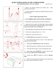
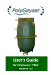
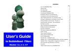
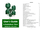
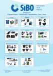
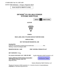
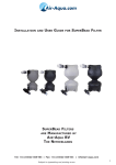
CONTENTS
Page Number
User’s Guide
to BubbleBead Filters
Models 1,2,4,6 &10
BubbleBead filtration for koi ponds
3
The principle behind all biological filter systems
4
The principal behind BubbleBead filters
4
How does such a compact filter compare to large chamber filters? 6
Choosing the correct size of filter; pump and U/V
7
Strainers
9
Table showing model capacity, flow rate, pump & UV options
10
Siting the filter
11
Filter assembly
12
Plumbing in
14
Important points - air breaks; aeration; the waste outlet bore
17
Waste water
18
Starting the filter for the first time
18
Running-in your filter
20
When to backwash the BubbleBead filter
22
Table showing recommended backwash frequencies
23
Long term maintenance
24
Winter running
25
Water quality maintenance
25
Water quality troubleshooting
27
Filter troubleshooting
30
Appendix One – Low siting
34
Appendix Two – Automated backwash options
35
Appendix Three – Pump assisted backwashing
35
Appendix Four – Combining BubbleBead filters with other equipment 37
Appendix Five – High pressure situations
40
References and Sources
41
Guarantee
42
Typical measurements for your BubbleBead filter
43
2
BubbleBead Filtration for Koi Ponds
The Principle behind all Biological Filter Systems
THE REQUIREMENT FOR FILTRATION
THE LIMITATIONS OF ‘NATURAL’ FILTRATION
Koi, and similar ornamental fish kept in any numbers, need some form of
filtration for their ponds. Koi soon pollute their surroundings due to their
greedy appetites and vigorous browsing nature, churning up the pool base. Any
form of filtration needs to remove the suspended solids (mechanical filtration)
and break down the dissolved fish wastes (biological filtration) to give both
clear water for viewing and clean water for fish health.
In natural lake ecosystems, micro-organisms build up on the surfaces of rocks,
plants etc. and help to break down wastes from the limited numbers of fish
present. In artificial systems, sediments are usually removed and pools often
kept clinically clean. The remaining micro-organisms struggle to cope with the
wastes from the relatively high numbers of fish stocked.
THE CAPABLE BUBBLEBEAD FILTER SYSTEM
The BubbleBead filter system is ideally suited to koi ponds, and has been
scientifically proven to remove particles to 15 micron size and below, whilst at
the same time efficiently breaking down biological wastes1,2 . A correctly sized
unit can achieve this clean & clear water quality on its own, or it can be used in
conjunction with ancillary filter equipment.
SELF-CLEANING FILTER FUNCTION
In the past, however advanced the filter system design, efficiency can suffer
due to lack of regular maintenance. This has proved a major problem with
many of the common ‘box’ and ‘chamber’ type filter systems where sediments
can build up in the units, rapidly releasing nutrients that promote blanketweed
and other algae. Cleaning such units can become a real chore. This is not a
problem for the BubbleBead filter where the hands-free backwash process is
simple and straightforward to run, allowing regular flushing out of collected
wastes.
BOOST EXISTING FILTER SYSTEMS ALSO
BubbleBead filters have shown themselves to be ideal to boost fish stock
capacity and solids removal in existing koi ponds where the current filter
system is becoming overloaded. For details of how to best integrate a
BubbleBead filter with existing filter equipment, see Appendix Four. The
compact size of the BubbleBead filter and its ability to be sited remotely makes
it ideal for retro-fitting in these cases, with minimal disruption to the surrounds
of the existing pond.
THE PURPOSE OF FILTRATION SYSTEMS
The natural micro-organisms that break down fish wastes are concentrated in
an external filter system. Water from the pool is re-circulated through the filter
to bring in the wastes, oxygen and other nutrients that these organisms feed
on. The filter also needs to remove suspended solids to prevent the water from
becoming turbid. To prevent the filter itself from becoming clogged, the dirt
needs to be periodically removed from the filter.
With browsing fish such as koi, the sediments are constantly disturbed into
suspension, aiding their transfer to the filter system. Removal of pool
sediments is usually supplemented e.g. by the addition of bottom drains that
can be flushed to waste, or the use of vacuuming devices.
The Principle behind BubbleBead filters
BubbleBead filters are based around a
media of small (3 x 5 mm), floating
plastic beads. In normal running, the
beads pack to form a filter bed that
efficiently captures solids by a
combination of processes including
straining and interception by the
biological film that forms on the surface
of the beads3. The very high surface area of the beads allows for the
attachment of large numbers of beneficial filter bacteria, which break down
fish wastes.
STANDARD FLOW PATTERN
Water is pumped in, through the inlet screen and up through the unit. The
floating beads pack down into a filter bed in the top of the unit, where both
3
4
biological breakdown of wastes and mechanical filtering of solids takes place.
Filtered water leaves through the outlet screen and outlet checkvalve.
The floating nature of the beads and the bead size allows for simpler cleaning
and less powerful pumps than used in e.g. sand filters. The inlet and outlet
strainers prevent loss of media, and the beads do not break down over time,
unlike some fluidised bed systems based on mineral media.
Bead filters have been in development since the early 1980’s leading to the
design and patenting of the BubbleBead filter by Ronald F. Malone at
Louisiana State University. The distinctive hourglass shape and bubble washing
process is a key to its effectiveness.
BACKWASHING
The pump is turned off and the waste (‘sludge’) valve (1) opened.
BACKWASHING MODE
How does such a compact filter compare to large chamber filters?
The gentle, bubble wash process is a key to the BubbleBead filter’s efficiency.
It aids cleaning of the beads whilst maintaining a thin healthy biological film on
the bead surface functioning at peak efficiency. This ensures that the maximum
proportion of bead surface area is available for biological filtration to take
place. The regular backwash also removes anerobic causing solids from the
system before they fully break down.
In many conventional filter systems the biological media becomes sedimented
with solids and the surfaces become coated in an excess thickness of biological
film which reduces the efficiency of the biological media. To compensate, a
much greater volume of biological media is required in such systems.
The inlet and outlet checkvalves (2 & 3) close and air is drawn in through the
air checkvalve. As the filter empties, the beads drop through the washing
throat and are tumbled in a cascade of air bubbles (4). Once dirty water has
flushed to waste the waste valve is closed and the pump re-started.
5
6
Choosing the correct size of filter; pump and U/V
The correct size of filter is calculated according to both the weight of fish in
the system and the overall system volume.
The weight of the fish is directly related to the amount of food that they
consume and this in turn is related to the amount of fish waste produced that
the filter has to deal with. As most koi keepers are unlikely to have weighed
their fish, the simplest way of relating filter size to fish stocks is to weigh an
amount of fish food equivalent to the maximum amount fed in one day.
It has been found that larger BubbleBead filters will not necessarily perform
any better on a given pond but they will require less frequent backwashing and
have a larger safety factor3. So, if in doubt, move up to the next size of filter.
The correct size of pump
Pump size is related both to the volume it pumps and the pressure with which
it pumps. The pumping volumes to aim for are listed on the table on page 10.
MINIMUM PRESSURES:
Experience has shown that bead filters can cope with a loading of up to ½ lb/
225 grams of food per cubic foot of media per day whilst giving water quality
acceptable for ornamental fish2,3. (This is equivalent to up to 50 lb/23Kg of
koi fed at a 1% feed rate; see table on page 10 for details). For maximum water
clarity and the best water quality this figure is halved to an upper limit of
¼
lb/113 grams of food per day per cubic foot of bead media.
There is typically a loss of pressure across the bead bed of around 1 to 2 psi
(equivalent to 0.7 to 1.4 metres of head) especially as the filter approaches the
time for backwash. Even pumps with a relatively low maximum head (2 to 3
metres) have been used successfully on the smaller models.
These figures are based on standard bead media and typical pelleted foods with
a protein content of around 35%. Conversely, the feed rate for very high
protein ‘growth’ foods would need to be reduced.
The filter hull itself has a maximum
pressure rating which should never be
exceeded. e.g. on models 1,2 & 4 the
0.7 bar rating is equivalent to a pump
head of 7 metres, and it should never
be exceeded. Take care if you use a
high pressure pump (e.g. a powerful
swimming pool pump) as these may
exceed the pressure rating, especially
on start-up when high pressure surges
can occur. For all pumps with a
quoted head exceeding 7 metres we
consider it essential to use a bypass
tee before the filter inlet, with a
pressure regulating spring-check-valve
to prevent excess pressures building
on the filter. A pressure gauge is also
strongly recommended in such
situations. See Appendix Five for
other hints on high pressure uses.
MAXIMUM PRESSURES:
The system volume limits how frequently the pool can be filtered by a given
size of filter running at a particular flow rate. In a very lightly stocked goldfish
pool with plants and with very high levels of ultra violet (UV) treatment to
control green water algae, the maximum volume treated by a filter may be as
much as four times the hourly flow volume through the filter. However, in
lightly stocked koi ponds, the maximum volume treated is around 3 times the
hourly flow volume through the filter ((1) on the table). For more typical koi
pond loading situations the volume treated should not exceed twice the hourly
flow volume through the filter ((2) on the table). In commercial stock tank and
aquaculture situations which are very heavily loaded, this volume may need to
be reduced still further and extra aeration provided.
Take into consideration both the weight of fish and the volume of the system
when choosing the correct filter. Remember that pump flows fall as the filter
starts to gather dirt and the pump strainer starts to clog. Therefore the flow
rates used when calculating the size of filter required should reflect typical
pump outputs when running through a moderately dirty filter rather than the
maximum flows found on new pumps running on newly cleaned filters.
7
Some swimming pool pumps are not
designed to be run at low pressures or low heads. As the pressure through a
8
BubbleBead filter may drop as low as 2-3 psi (1.4-2.1 metre head equivalent)
only use pumps whose recommended range drops this low.
PUMP OUTPUTS
The table overleaf gives suggested pump sizes in terms of maximum flow rates
at a given head and the maximum head rating of the pump. When using a filter
on a pond of less than the maximum capacity, reduce the flow rate accordingly.
Your dealer should be able to recommend suitable models from the ranges
available in your area. Remember that a small pump may not suit longer pipe
runs or high head situations. If in doubt, it is better to have a slightly larger
pump and use a valve on the pump, or a bypass to control excess flow, rather
than to have a small pump which has no spare capacity. Surface mounted
pumps should be of the self priming type or installed in a way that ensures they
cannot run dry.
The minimum recommended flow through any filter is 25-30% of the
maximum flow quoted. This flow should be sufficient to supply the filter
organisms with the necessary oxygenated water for efficient filtration.
ELECTRICAL SAFETY
Like all electrical equipment around the pond, the pump should be correctly
installed and fitted with a safety circuit breaker (RCD). The RCD should be of
the latching type that does not require resetting after a powercut. Some types
may be too sensitive to the power surges caused by turning the pump on and
off. In these cases a less sensitive RCD may need to be fitted – contact your
local electrician for advice.
The correct size of ultra violet (UV) unit
A UV unit is the most useful ancillary equipment to use with a BubbleBead
filter as it helps to control the very smallest (< 5 micron) free floating algaes
and blooms of bacteria which are too small to be readily captured by the filter.
Closed chamber type UVs (with a protective quartz sleeve for the bulb) are
recommended. Despite small differences in design, the major factor in most
UV unit performance is the wattage of the bulbs. See the table for the correct
size for green water control. Where the pond is heavily shaded, control may be
achieved with only half the wattages listed. In very shallow ponds and in more
southerly areas where sunlight intensity is higher, a higher wattage of UV light
may be required. A much higher wattage is required for water sterilization.
Clean and maintain the UV unit as recommended by the manufacturer. To
prevent back-pressure across the UV, choose models with a wide bore inlets &
outlets, rated for flows in excess of the max. filter flow listed on the table.
Rec.
Max Pond Max Feed
Rate
& Cubic
FlowRate
Volume
Feet of gallons (litres) per day
gph
(Koi load at
(2)
Media - Light(1)
(lpm)
1% feed rate)
Stock - Standard Stock
MODEL
BBF-1
2400
11000
1600
7250
0.5 lbs.
230 gm
500-800
37-60
(50lb/23Kg)
BBF-2
4500
20000
3000
13500
1.0 lbs.
450 gm
1000-1500
75-114
Suggested
Max.
Pumps
Pressure
Pre-settlement or preP.S.I.
straining is essential
with solids handling
(Bar)
BBF-4
BubbleBead filters contain an internal inlet screen with slots of around 2 mm
designed to capture large solids whilst preventing loss of beads. The backwash
process cleans these screens, but the rate of internal filter clogging is reduced if
solids of greater than 2 mm and strands of blanketweed are removed before
being pumped to the filter. It is very important to fit an appropriate strainer
to pump inlet (e.g. The EstroSieve Strainer – See Appendix Four). Solids
handling pumps in particular will require additional straining, e.g. place inside a
finer strainer basket. Alternatively draw water from after a settlement area.
Very fine additional strainers (e.g. open-cell foam blocks) are not normally
necessary or desirable unless specified by pump manufacturers.
9
9750
44000
6500
29000
2.0 lbs.
900 gm
The maximum head of
the pump should be at
least 2.0 metres more
than the working head
or exceed 4.0 metres,
whichever is the higher
figure.
BBF-6
13500
60000
9000
40000
BBF-10 22500 15000
100000 68000
10
(0.7)
alternatives
2 x 30w
4 x 11w PL
10
(0.7)
3.0 lbs. 3000-4500
1.36 Kg 225-340
The maximum head of
the pump should be at
least 2.5 metres more
than the working head
or exceed 5.0 metres,
whichever is the higher
figure.
15
(1.07)
5.0 lbs. 5000-7500
2.27 Kg 375-570
(500lb/227Kg)
10
N.B. A pressure
release bypass is
essential when using
higher pressure pumps!
30w
alternative
2 x 11w PL
The max. head of the
pump should be at
least 2.5 metres more
than the working head
or exceed 4.5 metres,
whichever is the higher.
(300lb/136Kg)
for algae
control
10
(0.7)
2000-3250
150-245
(200lb/90Kg)
U/V
pumps!
(100lb/45Kg)
Strainers
Recommended
15
(1.07)
55w
2 x 55w
alternatives
3 x 30w
3 x 36w PL
3 x 55w
alternatives
4 x 30w
4 x 36w PL
4 x 55w
alternatives
7 x 30w
6 x 36w PL
Siting the filter
1) The filter needs to be mounted on a firm level base. The units are heavy
when full of water and must be adequately supported for safety. A bed of
levelled gravel is adequate for the smallest filter but the larger models benefit
from being positioned on a purpose made slabbed area or concrete plinth.
Ideally the base of the filter and the waste outlet should be above the level of
the water in the pond. (See Appendix One for low site situations.)
5) The filters are suited to outdoor use but if sited in an outhouse, shed or
garage, they will not only be out of sight from the pond but also better
protected from severe frosts (see the section on Winter Running – page 25).
Filter Assembly
The assembly instructions for models BBF-1, 2 & 4 follow here. Larger filters
are supplied with a separate set of specific assembly instructions. Read through
these instructions and this guide before fixing the filter permanently.
2) The efficiency of the backwash cleaning process is directly related to the
speed with which water drains through the waste valve. This in turn is related
to the ‘siphon head’ (see diagram) between the filter waste outlet and the air
strainer inlet to the filter. This distance is around 15-30 cm on the filters as
supplied, which is adequate in most circumstances. However, by simply raising
the filter on a plinth built from two courses of standard building blocks and
adding an extension pipe, the siphon
head is increased and the efficiency
of backwash greatly improved.
Where it is not possible to increase
the siphon head, the Pump Assisted
Backwash (PAB) option should be
considered. The PAB also suits sites
with poor drainage and high water
tables; where the waste water needs
to be pumped any distance e.g. for
irrigation; or in situations where the
filter is particularly heavily loaded
with fish waste or blanketweed.
Details are given in Appendix Three.
3) The filter can be some distance
from the pond, although a larger
pump may be required in this case to
overcome the friction loss in the
longer pipe runs.
4) The filter should be as close to
your drainage system as possible, for
ease of waste water disposal.
11
(BBF-4 layout is similar to BBF-1 & 2 above but with 2” fittings instead of 1½”)
#1A & 1B Inlet and Top Outlet Screens (interchangeable)
#2
Flexible hose with fixed threaded ends (for additional drain)
#3
1” NPT threaded ballvalve for the unscreened additional drain
#4
1½” 90° elbow (male NPT x female NPT (NPT = US Pipe Thread))
#5
Air inlet with screen
#6
Air inlet assembly with ¾” swing-check valve
#7
12” extension pipe with 1½” male NPT ends
#8
1½” tee; solvent x solvent x female NPT side arm
#9
Points for insertion of sections of 1½” PVC pipe c.6” long (not shown)
#10
1½” adapter; solvent weld x male NPT
#11
1½” NPT threaded ballvalve (Main waste valve)
#12A & 12B 1½” swing-check valves (solvent weld) for main inlet/outlet flows
#13
Bead media
#14
1½” 90° elbow (male NPT thread x female solvent weld socket)
12
Remove the filter from its box and lie it on its side in a clean dry area. Lay out
the various pipe fittings in a similar order to the adjacent picture and check
that you have all the necessary equipment to hand. You will require large pliers
or a pipe belt wrench; a spirit level; PVC pipe cleaner and cement; and a funnel
to assist in adding the beads. PTFE tape is included in the kit.
1) Prepare all male threaded fittings by wrapping round the threads several
times with PTFE tape. With the insertion end of the fitting facing you, wrap
the tape on in a clockwise direction. If the tape is wound on in the wrong
direction it will tend to peel off as the fitting is screwed in.
2) Install one of the screens (Part #1) in the hole in the centre base of the
filter. See the plumbing tips on pages 14 - 16. Hand tighten and then use pliers
or a pipe wrench to tighten a further 1/2 turn. Do not over tighten.
3) Thread one end of the flexible hose (Part #2) into the 1” threaded hole
adjacent to the base inlet.
4) Thread the elbow (Part #4) into the inlet screen in the base of the filter.
5) Thread the air inlet (Part #5) into the hole in the side of the filter, inserting
the screened end first.
6) Site the filter base so that it is level, preferably in the final position required
for the filter. Lift the filter onto the stand. The approximate weight of filters
without beads, but including stand and fittings, is BBF-1, 14Kg ; BBF-2, 22Kg;
BBF-4, 33Kg. The larger filters exceed guidelines for lifting by a single person
and are likely to require extra help with moving.
Rotate the filter so that the elbow (Part #4) is facing the cut-out in the base.
Flex the hose (Part #2) so that it protrudes from the other cut-out in the base.
7) Screw the extension pipe (Part #7) into the elbow (Part #4) and screw the
tee piece (Part #8) onto the other end. Tighten so that the tee is in a horizontal
position.
fitting the automated backwash option as this may require a different fitting
here).
10) Glue another piece of pipe (Part #9) onto the other side of the tee and
glue one of the swing check-valves (Part #12) onto the other end. The swing
check-valve must open towards the tee and be in a horizontal position with
the “hump” on top to assure that water will flow into the filter correctly and
that the valve will close properly when the pump is stopped.
11) Thread the additional drain valve (Part #3) onto the open end of the
flexible hose (Part #2) and ensure that the valve is in the closed position.
12) If the filter has not already been moved to its final site, do so now. It will
be much heavier once the beads have been added. Using a funnel, pour the
bead media into the top of the filter through the main outlet opening. Avoid
any dirt getting into the outlet threads.
13) Screw in the top outlet screen (Part #1B) and tighten as per instruction 3.
14) Screw the remaining elbow (Part #14) into the opening in the top screen
and glue in the remaining piece of pipe (Part #9).
15) The remaining swing check-valve is glued onto the other end of this pipe.
(We strongly recommend fitting a dismountable union on one or other side of
this valve - see page 16). The valve must open away from the filter and be in a
horizontal position with the “hump” on top to assure that water will flow
out of the filter correctly, and that the valve will close properly when the pump
is stopped. Give the glue time to set completely.
16) Attach the air inlet assembly (Part #6) to the air inlet (Part #5) and tighten
both parts so that the check valve at the end of the assembly is pointing
vertically down or up.
Plumbing in
9) Screw the threaded end of the adapter (Part #10) into the large ball valve
(Part #11) and then glue the solvent-weld end of the adapter (Part #10) onto
the other end of the section of pipe you have just fitted. This assumes that you
are using this standard waste valve. (Contact your dealer if you are considering
Plumbing to and from the main filter valves can be carried out using solid or
semi-flexible swimming pool pipe using glued fittings, or a reinforced flexible
PVC hose using hosetails and threaded or glued fittings. If you are using
flexible hose, ensure that it is a heavy duty, smooth bore type rated for well
over the pressures likely to be found in the system (e.g. over 3 bar/45 psi). Use
fully opaque hose to prevent algae growth on the inside wall of the hose as this
can rapidly reduce flow rates as well as looking unsightly. If you are fitting an
automatic backwash valve, details are given in Appendix 2.
13
14
8) Glue one of the pieces of pipe (Part #9) into the side of the tee that is
closest to your drain. (The other side of the tee is for the main inlet from the
pump. The adjacent diagram layout is just one option.)
Tips for inserting threaded fittings
With the insertion end of the male fitting facing you, tightly wrap the P.T.F.E.
tape on in a clockwise direction. If the tape is wound on in the wrong direction
it will tend to peel off as the fitting is screwed in.
TO PREVENT STRAIN ON THE FILTER INLET/OUTLET FITTINGS:
- support pipework with pipe-clips etc.
- avoid the weight of pumps or external UVs being carried by the
inlet/outlet fittings. Failure to note this could void your guarantee.
TO PREVENT LEAKS OF WATER OUT, OR AIR IN:
- use PTFE plumbers tape on all threaded fittings.
- use solvent cleaner on any solvent-weld fittings before use and use ample
amounts of an appropriate glue. Set up solvent fittings in a ‘dry run’ to check
positionings before final gluing takes place. Glue needs time to set!
- use correctly sized hosetails and appropriate hose clips. If the hose is slightly
loose on the hosetail, run a strip of silicone sealant around the hosetail before
fitting the hose and clamping down. Clips can distort hose causing leaks if
over-tightened. TIP: To reduce this risk, wrap the end of the hose with a single
layer strip of rubber liner before fitting the clip.
Gently brush out the threads on the female fitting to ensure that they are clean
and free from debris. Align the male and female threads carefully to avoid
cross threading. Whilst exerting slight pressure, turn the assembly counterclockwise a half turn or so, until the threads align. Now screw the male fitting
clockwise by hand, continuing to take care to avoid cross-threading. If the
fitting does not appear to be threading in correctly, carefully remove it and
start again. Applying silicone lubricating spray to the female threads can often
make the threading process more easy.
Take your time and do not rush this procedure
Only use tools (e.g. belt wrenches) to tighten fittings once they have started to
thread in correctly. Do not use tools which might damage the threads or the
fittings and avoid using projecting pipework as a lever.
Never overtighten or force fittings otherwise you will damage them.
TO SIMPLIFY FUTURE MAINTENANCE:
- use good quality dismountable
connections on the pump, filter inlet &
outlet, and any external UV unit, e.g.
female ‘nut and liner’ hosetails, or
dismountable unions (see right), or
bayonet fittings with an ‘o’ ring seal.
- use sufficient flexible hose on
submersible pump outlets
- keep UVs and valves accessible.
TO PREVENT EXCESS PUMP VIBRATION:
- use some flexible hose in the outlet pipework from surface mounted pumps.
Plumbing tips:
TO AVOID CORROSION OR POISONING PROBLEMS:
- try to avoid metal fittings
- if metal parts are used, choose quality materials e.g. (316) stainless steel.
TO MINIMISE PRESSURE LOSS ON THE INLET
AND BACKPRESSURE ON THE OUTLETS:
- use larger bore pipe/hose wherever an option is possible
- all pipe fittings (including UVs) must be as large bore as possible
- avoid fittings with internal restrictions.
- avoid using valves on the outlet! (see Appendix Five).
- if required, consider swept or 2 x 45° bends rather than knuckle bends.
TO MONITOR THE PRESSURE IN THE SYSTEM:
- if a high pressure pump is being used, fit a pressure gauge just before the
filter inlet. This is strongly recommended for pumps with over 7m (23ft)
head. It is also useful in heavily loaded aquaculture systems to monitor the rate
of solids collection within the filter. On systems fitted with a high pressure
pump, or where filters are feeding manifold or valved outlets, it is essential to
fit a pressure release bypass (see Appendix Five).
15
16
Important points
Waste water
The additional drain valve is for the occasional removal of sludge that builds
up in the base of the filter. Turning it on once a month for a few seconds is
more than adequate. To avoid extending the hose it can be run into a bucket
and poured to waste. It is an unscreened drain, only turn it on when the filter
is running full of water, otherwise beads can be lost!
The waste water will be fairly high in solids and organic waste and should not
be emptied directly into streams or natural water bodies. Check if you need
permission to dispose of this waste in the public sewer system.
AIR BREAKS AND UNDERPRESSURE
If the outlet on the main return pipe to the pond is below the level of the air
inlet checkvalve on the filter, there is a slight risk of siphoning occurring. This
is more prevalent on new/clean filters, with relatively low pressure pumps and
wide bore piping on the return to the pond.
Provided salt or chemicals have not been used in the pond it should be safe to
use this waste water to irrigate garden plants, indeed the waste will have a
beneficial fertilizing effect. To avoid restricting the flow of waste from the
filter, avoid long irrigation hoses and use a separate sump and sump pump.
Alternatively fit the pump assisted backwash option (see Appendix Three).
USING A SUMP PUMP TO DISPOSE OF WASTE WATER
A side effect of this siphoning action is that air can be drawn into the filter
through the air inlet during normal running (especially with lower pump flow
rates). These bubbles can disrupt the filter media causing water cloudiness and
a dripping air inlet.
Higher return outlets (e.g. to a cascade), avoid this risk. Ideally, the return pipe
to the pond should enter above water level to create an air break. This reduces
the risk of such siphoning and also aids aeration of water returning to the pool.
AERATION OF FILTERED WATER RETURNED TO THE POND
Koi pond water must be aerated at some point as both the koi and the filter
bacteria can consume high amounts of oxygen, especially in warm weather.
Returns that encourage some re-aeration of the water are strongly
recommended, e.g. cascades. Venturi devices in the pond are an option but
some create a great deal of undesirable backpressure whilst others can
encourage the underpressure noted above.
THE WASTE OUTLET BORE
Any pipe or hose connected to the waste (sludge) outlet should have a bore at
least as large as the valve fitted and should flow downhill to a drain or sump
area to encourage rapid draining of the filter (see also the section on siting on
page 11). To prevent air-locks make sure there is an air break at the end of this
pipe (it should not empty below water surface) and avoid undulating pipe.
17
Starting the filter for the first time
Set the valves to the standard operating positions with the main waste valve
closed and the additional drain valve closed. Start up the pump, do not turn on
the UV at this stage. Check for leaks. The beads will rattle against the side of
the unit as it fills but the noise will stop once the filter is full. On this first time
of running you may wish to direct the first few gallons of water to waste as
18
they flush out any dust and grime from the pipework. If there are no leaks and
water output is flowing evenly, your BubbleBead filter is operating properly. If
any of the threaded fittings leak, and gentle tightening does not help, the filter
will need to be drained, the offending fitting removed and rewound with extra
PTFE tape before refitting. Do not attempt to seal such leaks by smearing the
outside of the filter with sealant, glue, mastic or repair compounds. This rarely
solves the problem, it may make future dismantling difficult or impossible, and
damage the filter body - voiding your guarantee. Now is a good time to carry
out the trial backwash cycle.
1. Turn off the pump. The main inlet and outlet check-valves will close.
2. In low-site situations (see Appendix One), close any valve connected in the
feed from the submersible pump. If not installed, the check-valve will still
prevent water from flowing back through the pump into the pond.
3. Make a note of the time or use a stopwatch. Now open the main waste
valve (90° turn). Put your ear to the side of the filter and listen. Air will be
sucked into the filter through the air inlet check-valve. Beads tumble clean
in a cascade of air bubbles and rattle against the side of the hull. Allow the
filter to drain down completely. This first time, the water from the waste
valve should be no more dirty than the pond water itself. By listening to the
unit, you can hear how a normal backflush should sound.
4. As soon as the flow drops to a trickle from the drain, close the main waste
valve. Make a note of the time or turn off your stopwatch. The time taken
to drain the filter is representative of the minimum time that your filter is
likely to take for a backwash cycle and will act as a benchmark to compare
with in future. It would be a good idea to note this time in the space on
page 43.
5. With the waste valve closed, and any manual valve in the feed from the
pump open, restart the pump. Note the time taken for the filter to refill.
This will also act as a benchmark for the future as it gives an indication of
the cleanliness of the strainer on your pump and the screen in the filter
inlet. It would be a good idea to note this time in the space on page 43.
Your filter is now tested and operating correctly.
Running-in your filter
Your filter must run 24 hours a day to support the biological organisms that
will colonise the filter media; just like your fish they need oxygen to survive.
If you have a pressure gauge fitted, note the typical pressure on the dial after
starting up filtration and make a note of it in the space on page 43. Mechanical
filtration starts almost straight away, but it takes some weeks for full biological
activity to mature, especially in brand new ponds and in cold weather. Patience
is necessary during this phase. If there are no fish in the pond, commercial
additives are available that contain ammonium salts and nitrites that imitate
fish waste and help the filter to mature. Otherwise, there are a number of steps
that you can take to aid the maturing process:
1) Do not introduce large numbers of fish. Build up fish stocks gradually using
hardy fish of lower value to begin with.
2) Feed more lightly than normal in the first two months.
3) After the first few days of operation, add a commercial filter seeding agent
that contains filter bacteria. Alternatively swill out the debris from an existing
active pond filter and pour it into the pond near the pump intake.
4) Avoid the use of pond medications during the filter maturing period. Some
medications can severely disrupt filter organisms and many medications can
temporarily reduce filter activity, especially on the first time of use. If in doubt
ask a specialist before using any treatments.
5) Avoid turning on UV units during the first two to four weeks. The water
may green temporarily but this should not be harmful.
You can monitor the maturing process by using standard pond test kits. The
most useful ones at this stage are pH, nitrite (NO2), ammonia/ammonium
(NH3/NH4) and nitrate (NO3).
The pH should remain relatively steady and need only be checked occasionally
at this stage Typically, acceptable pond pH values range from 6.5 to 9.0 with
the ideal range for pondfish being between 7.0 and 8.5.
The major soluble waste product produced by fish is ammonia and its
ammonium salts and this is the first product to build up in the water. Bacteria
19
20
that break down organic wastes and uneaten food also add to the levels of
ammonia in the water. Within a week or two (in a few days in warm weather),
specific bacteria that feed on ammonia start to build up on the surfaces of the
beads in the filter, and they begin to break the ammonia down into nitrites. As
the nitrite levels become more detectable in the water, the ammonia levels
usually start to fall. Finally, other specific bacteria grow in numbers to feed on
the nitrites converting them to nitrates. The whole process that results in the
breakdown of these nitrogen containing products is known as nitrification
and the fluctuations in these waste products typically follows the pattern
illustrated in the adjacent graph
TYPICAL WATER QUALITY DURING FILTER MATURATION
When to backwash the BubbleBead filter
During the maturing period, whilst new ponds are relatively free of waste, the
filter will take some time to become dirty. The delicate film that supports the
growing filter bacteria will also begin to form on the surface of the beads. In
order to avoid disrupting the bacteria at this crucial early stage avoid
backwashing the filter for up to two to four weeks, especially in ponds with
clean water. The major sign that a backwash is necessary is when there is a
notable drop in the flow from the filter outlet. Check that this is not merely
due to the strainer on the pump becoming clogged.
If the flow has dropped to around a half to two thirds of the initial rate, or the
inlet pressure gauge (where fitted) has risen to 0.1 bar (1.4 psi) above the
typical level when clean, then the backwash procedure should be carried out.
The standard backwash cycle is as follows
1. Turn off the pump
2. In low-site situations (see Appendix One), close any valve connected in the
feed from the submersible pump. If not installed, the check-valve will still
prevent water from flowing back through the pump into the pond and should
prevent above-pond pumps from losing prime.
Ammonia and nitrite are both stressful to fish and, whilst they are present in
the water, new additions of fish should be avoided. Once the filter has matured
sufficiently, these two waste products should be reduced to below detectable
levels and only the more benign nitrate may be detectable. However, a sudden
increase in loading at this stage (with fish or fish food) may overwhelm the
filter resulting in a reappearance of ammonia and nitrite until the filter bacteria
can increase in numbers to cope.
If ammonia or nitrite appear in the water after the maturing period it can
suggest problems, and these are dealt with in the Water Quality
Troubleshooting section of this guide.
21
3. Open the main waste valve (90° turn). The main inlet and outlet checkvalves will close and air will be sucked into the filter through the air inlet
check-valve. Beads tumble clean in a cascade of air bubbles. Remember to
listen for typical sounds. Observe the waste water. Large particles caught by
the bottom screen will flush out first; dirt trapped by the beads will wash out
near the end of the flush. For best results allow the filter to drain down
completely.
4. As soon as the flow from the drain drops to a trickle, close the main waste
valve.
5. With the waste valve closed, and any manual valve in the feed from the
pump open, restart the pump.
6. It is quite normal for the first few gallons of water from the filter outlet to
the pond to be a little dirty. This is not harmful and the filter will soon remove
22
these particles and maintain the clarity of the pool. It makes sense not to carry
out a backwash just before any important viewing of the pond.
Long term maintenance
After this first backwash, the standard backwash frequencies must be
implemented.
MONITORING
Once established, the beneficial bacteria building on the surface of the beads
can withstand numerous backwash cycles without any major disruption of
nitrification. Indeed, tests have shown that the gentle bubble-wash actually
improves the efficiency of nitrification by the filter bacteria.
The Recommended minimum backwash cycles for your model are noted
in table below.
MODEL
BACKWASH FREQUENCY
Typical Water
Loss
Winter
Spring &
Autumn
Summer
BBF - 1
Twice Weekly
Every One to
Two Days
Every One to
Two Days
10 gallons
45 Litres
BBF - 2
Twice Weekly
Every One to
Two Days
Every One to
Two Days
21 Gallons
95 Litres
BBF - 4
Twice Weekly
Every One to
Two Days
Every One to
Two Days
38 Gallons
170 Litres
BBF - 6
Once or Twice a
Month
Weekly
Three to Four
times a Week
54 Gallons
247 Litres
BBF - 10
Once or Twice a
Month
Weekly
Three to Four
times a Week
125 Gallons
570 Litres
A series of extra backwashes once per month, reduces long-term maintenance (see p.24).
On automated systems a backwash once or twice a day gives ultimate filter performance.
Regular backwashing flushes out solid wastes before they break down and
pollute the water. Also, by removing wastes at this stage, nutrients are removed
from the water and the growth of algae can be reduced further. The process
keeps the filter at maximum biological efficiency and minimises the need for
any other maintenance. Regular backwashing is essential in heavy loading
situations. You simply cannot backwash a BubbleBead filter too often.
The optional automatic backwash facility can be set to run at the desired
intervals (See Appendix Two).
23
It is very important to periodically monitor the backwash operation:
- listen to the beads sloshing in the filter
- check the backwash time and the action of the valves.
Monitoring shows up any possible problems before they become serious.
MONTHLY EXTRA BACKWASHES
We recommend that once a month the backwash process is carried out three
to five times in a row. This dislodges any more persistent wastes that may have
collected in the filter. On heavily loaded aquaculture systems this procedure
can be carried out every one to two weeks.
ADDITIONAL DRAIN
The additional drain can be opened for a few seconds, once a month, to flush
out any solids gathering on the very base of the filter. It is an unscreened
drain, so only turn it on when the filter is running full of water otherwise
beads can be lost!
Over time, the filter inlet and outlet screens may slowly clog with more
persistent immoveable dirt or strands of algae, especially if an inadequate
strainer is being used on the pump. Periodic removal and cleaning of the
screens may prove necessary in these cases. See the Filter Troubleshooting
section for more details.
CHECKVALVES
The top-outlet checkvalve and air inlet checkvalve are low maintenance items.
Very occasionally the facing or seating may need cleaned. If the air inlet drips,
see the troubleshooting guide (page 31) and the section on air breaks and
underpressure (page 17).
PUMP STRAINERS
Remember that the strainer on the pump will need to be cleaned from time to
time. If this becomes clogged with debris or blanketweed the filter may not fill
correctly, and flow rates will be affected.
24
Winter Running
In the winter, when temperatures are lower (below 8-10oC), koi feeding rates
are reduced and maintenance can be less frequent. To avoid chilling the fish in
water currents, avoid drawing in water from the pool base and instead draw
from 30-60 cm below the surface. Consider reducing the flow rate through the
system – biological and filtering activity will still take place in the BubbleBead
Filter even at a quarter to a third of maximum recommended flows.
Ice can damage your filter! Insulate pipework; the filter; and the UV, where
penetrating frost may be a problem, taking especial care of pipes where there is
little water movement e.g. the air inlet pipe, the waste pipe and valve, and the
additional drain and valve. Standard closed-cell pipe insulation wrap and hotwater-cylinder jackets can be used but make sure that they are kept dry for
maximum insulation. In very exposed situations, the air inlet checkvalve on the
BBF-4, 6 & 10 can be mounted inside the filter to protect it from freezing. As
the filter is sealed, and produces no smells, it is often desirable to position it in
a frost-free outhouse, garage or utility room. This gives additional protection
from freezing even if the pump should stop due to power failure.
On smaller systems and in very cold climates an option is to turn the filter off
after the first severe frost and leave it clean and dry until the spring. In this
case carry out four backwashes in a row to leave the filter as clean as possible
before draining dry. Ensure all valves are left open to prevent ice forming
inside the units. Open the additional drain last of all, to minimise bead loss.
Water Quality Maintenance
Remember that although the filter may have passed its initial maturing period,
all biological filters continue to mature over months and years as different
micro-organisms establish on the filter media. This maturing process can be set
back by long power cuts or when pool treatments are used, especially on the
first time of use.
PARTIAL WATER CHANGES
The water quality also continues to change due to the gradual build up of
products in the water e.g. nitrates (NO3) and dissolved solids. Conversely,
some minerals may become depleted in the water as they are used up by the
fish, plants and filter organisms. In natural ponds and lakes this aging process
in the water body is offset by streams and heavy rains which bring in fresh
25
water and new supplies of minerals and flush out wastes that are building to
excess levels. In a closed system like a koi pond it is therefore necessary to
carry out regular partial water changes to mimic these natural refreshing
processes.
The backwash process loses some water which will need to be made up with
new water added to the pond. It is possible to install automatic top-up valves.
This waste removal and top-up acts as a partial water change. In systems
running close to maximum pool volume capacity, the lower recommended
frequency of backwashing might only result in a water change of around 1% in
a summer week. This level of water changing is much too low to maintain
water quality in the long term and additional partial water changes will be
necessary.
SET THE BACKWASH FREQUENCY TO WATER CHANGE FOR YOU
The most easy option is to set the backwash frequency at a rate that will give
the level of water change required per week. The table on page 23 gives typical
water losses per backwash. Remember that a high frequency of backwashes
does not upset the filter organisms but actually improves filter efficiency.
Adding water to make up for evaporation is not equivalent to a water change,
as this does not remove any waste products. Water needs to be removed from
the pond e.g. through the backwash cycle; from a bottom drain; or with a pool
vacuum; before water is added. Use a tap water conditioner or appropriate tap
water filter to make chlorinated water safe to add to the pond. Take advice
from local specialists if your source of water is direct from borehole or high in
metals such as iron.
MONITOR YOUR POND AND FISH TO AVOID PROBLEMS
Monitoring general water appearance and fish behaviour are invaluable as a
guide to water quality but the only sure way to know, is to carry out regular
water quality checks. Use a range of good quality pond test kits as stocked by
all major aquatic stores. By keeping a record of changes in water quality,
problems can be avoided before they take hold, and the overall health of the
fish and pool system maintained. The following troubleshooting guide to water
quality is a summary to be used in conjunction with other sources of good fish
husbandry. It is best to read through it before problems occur.
26
u If any problems occur, carry out a full range of water quality tests.
drops. If these minerals have become exhausted, the pH can drop suddenly.
Low pH values can directly irritate fish gills and mucous membranes as well as
reducing the efficiency of nitrifying bacteria in the filter. Some metal
compounds (e.g. copper) are also more toxic to fish at low pH levels.
? - Fish are hanging near the water surface and/or mouthing at the
water surface
u Immediate: Reduce or cease feeding. Check carbonate hardness (KH) levels
(see below). Carry out partial water changes.
w This can indicate a lack of oxygen entering the fish bloodstream. It may be
due to low oxygen levels in the water or other problems with water quality or
the gills of the fish which are preventing the fish from extracting oxygen from
the water. Less oxygen dissolves in the water in hot weather; in salty water; and
at high altitude. Oxygen levels may also drop due to large amounts of decaying
waste, or excessive growths of algae using up oxygen at night.
u Long term: Monitor KH levels & increase the rate of partial water changes.
Water Quality Troubleshooting
Questions (?), Comments (w), and Actions (u)
u Immediate: Increase oxygen levels by encouraging splashing at the water
surface with cascades or fountains. Use air pumps and airstones in the pond.
Temporarily reduce or cease feeding. Keep the water surface free from excess
floating leaves. Examine fish gills for signs of damage or parasite infection.
Carry out a partial water change taking care to remove decaying sediments.
? – The carbonate hardness (KH) is unusually low (below 3 degrees)
w Carbonates and bicarbonates ( CO3 + HCO3 ) represent the alkalinity and
buffering capacity of the water. These are used up by the filter bacteria in the
process of nitrification. The problem is most notable in systems where the
water is naturally soft (KH 3° / 50ppm or less) and feeding rates are high.
u Immediate: Reduce or cease feeding. Carry out a series of partial water
changes. Consider the cautious use of buffering compounds such as sodium
bicarbonate (NaHCO3) or powdered calcium carbonate (CaCO3).
u Long Term: Carry out control measures on excess algae growth. In heavily
stocked systems, consider the permanent installation of additional aeration
devices e.g. trickle towers.
u Long term: Increase the frequency of partial water changes. Choose a
replacement water source with naturally high carbonate levels. Add slow
release buffers to the pool system e.g. tufa rock; crushed oystershell. In heavily
loaded systems the regular addition of carbonate buffers may be necessary.
? – The pH is rising unusually high (over 9.0) – alkaline conditions
? – Ammonia/Ammonium levels (NH3/NH4) are high
w High pH values can directly irritate fish gills and mucous membranes as
well as reducing the efficiency of nitrifying bacteria in the filter. Waste
products such as ammonia are much more toxic to fish at high pH levels.
w Outside the filter maturing period, high ammonia levels are usually caused
by overloading or disruption to the filter organisms.
u Immediate: Reduce or cease feeding. Check ammonia levels. Carry out a
series of partial water changes. Consider the cautious use of pond pH buffers
designed to lower pH values.
u Long Term: Discover the source of the high pH. If it is due to uncured
cement-work, this may need to be removed from the system or sealed in some
way. If it is due to the replacement water source get advice from your local
supplier. If it is due to strong photosynthetic activity by algae, carry out algae
control measures.
? – The pH is unusually low (dropping to below 6.5) – acid conditions
u Immediate: Reduce or cease feeding. Increase aeration. Check and remove
causes of filter disruption. Carry out partial water changes.
u Longer term: Aim to avoid high pH values as ammonia is more toxic in
these situations. Take steps to prevent future disruption/overloading of the
filter. Add commercial cultures of nitrifying bacteria to the system.
? – Nitrite levels (NO2) are high
w Outside the filter maturing period, high nitrite levels are usually caused by
overloading or disruption to the filter organisms, or pockets of decaying
material building up in anaerobic (low oxygen) areas in the system.
w pH levels can fall due to the build up of nitrates or carbon dioxide (CO2) in
the water. Minerals in the water usually buffer the pH preventing sudden
u Immediate: Reduce feeding. Increase aeration. For salt tolerant fish such as
koi, add 3 grams per litre* (0.3%) of food-grade salt to the water as this
reduces nitrite toxicity. (*maximum of 1g/L (0.1%) with plants)
27
28
u Long term: Take steps to prevent future disruption of the filter; ensure that
it is being backwashed sufficiently; add commercial cultures of filter bacteria.
? – Nitrate levels (NO3) are high (over 100 mg/L total nitrate)
w – Nitrates build gradually in most closed systems. They are not especially
harmful to freshwater fish and immediate action is not called for unless levels
exceed 500 mg/L. However, chronic, high levels of nitrate are considered to
lower the immunity of fish to disease.
u Long term: Carry out more frequent backwashes and/or partial water
changes. Consider using plants to reduce nitrate levels. Monitor KH levels.
? – There is a high level of suspended solids in the water
w Suspended solids can irritate the gills of fish. Organic solids reduce oxygen
levels and increase levels of bacteria in the water which may cause gill disease.
Filter Troubleshooting
? – The water has suddenly become green / milky grey
u Algae blooms (green water) and bacterial blooms (milky grey water) can
sometimes occur, especially during the maturing period or following a sudden
increase in dissolved nutrients. The problem will be controlled by an effective
UV unit. If a UV does not appear to be working, check the bulb and clean the
quartz sleeve if necessary. Water with high mineral content can sometimes coat
the quartz sleeves and the filter beads in scale; use of magnetic devices often
alleviates this problem. Other sources of cloudiness include excess food and
particles washed in from surrounding soils. Temporarily cease feeding and
consider the very sparing use of flocculating agents.
? – The water has suddenly become very dirty
u Long term: Increase the circulation in the system to remove particles to the
filter more quickly. Use bottom drains to remove heavy sediments. Only feed
what the fish readily consume in a couple of minutes at any one time.
u If air is being drawn into the filter system during normal running, it will
disturb the beads and prevent them from catching dirt properly. Check that
there are no pipework leaks around the pump or filter inlet and that the pump
is not drawing in air from e.g. airstones. Check that the filter return to the pool
has not been moved to a lower position, or into the water itself, as siphoning
at this point can draw air into the filter through the air inlet valve (see page 17 air breaks and underpressure).
? – The water has a yellow tint
? – There has been a powercut
w In any closed system there is a gradual build up of complex waste
compounds e.g. phenols, which cannot be easily broken down by the filter.
These can eventually discolour the water but are not normally harmful.
u If the powercut has only been for a few hours, there should be no
problems providing the filter has been maintained correctly. RCD devices on
the system should be latching types that will restart automatically. If the filter
has not been backwashed recently; or if feeding levels are particularly high; or
the weather is particularly warm; then the filter organisms will run out of
oxygen more rapidly. In these cases or where the powercut has been lengthy
(over 12 hours), carry out a backwash to remove foul water and dying
organisms before restarting the filter. Avoid feeding for a few days and
monitor the water for ammonia and nitrite.
u Immediate: Find and remove the source of the solids e.g. poor quality or
inappropriately sized food; run-off from surrounds following rain.
u Long term: Increase the level of backwashes and/or partial water changes.
Temporarily use activated carbon in the system. Use a protein skimmer (foam
fractionator) in salt water systems. Changing food brands can sometimes help.
? – The water has excessive amounts of foam at the surface
w Foaming is caused by high levels of surfactants in the water, the most
common being types of protein. Some foaming may be expected during the
filter maturing process but this usually disappears once the filter has matured.
u Immediate: Carry out a partial water change taking care to remove uneaten
food and excess sediments. Consider the use of anti-foaming treatments
designed for fish ponds.
u Long Term: As for yellowed water (above). Check that any open cell foam
products used in the pool are fish-grade. Consider a surface skimming device.
29
30
? – The filter takes much longer to drain during a backwash
? – The pressure gauge reading does not drop to the normal level after
cleaning
? – I can hear the bead bed dropping in one lump (with a ‘thunk’)
during the backwash cycle
? – The filter sounds different during the backwash cycle
u Slow draining can be due to gradual clogging of the inlet and/or outlet
screens inside the filter, or ‘gelling’ of the bead bed. Screen clogging can be due
to strands of algae; growths of sponge-like bryozoans within the filter; or tiny
snails which have become wedged in the slots. Gelling of the bead bed is
caused by beads sticking together due to an excessive growth of the biological
film on the bead surfaces resulting from infrequent backwashing.
Regular backwashing of the BubbleBead filter can eliminate most of
these problems before they occur.
If these problems do occur, backwash your filter four to five times in a row
and increase the frequency of the regular backwash. If problems still persist:
Remove and clean the inlet/outlet screens on the BubbleBead filter. If the
lower screen has clogged rapidly, improve the strainer on your pump inlet.
Take steps to improve the backwash strength e.g. increase the siphon head (see
page 11), minimise restrictions on the waste outlet, or fit the pump assisted
backwash option (see Appendix Three).
For persistent gelling of beads either:
- turn off the pump and leave the filter full of water, inject air into the air inlet
valve with a blower or strong aquarium airpump for 30 to 60 minutes. The air
will accumulate under the bead bed eventually working its way upwards and
breaking up the beads. Then carry out the backwash process 4 or 5 times in a
row before restarting the filter.
- Partially drain the filter, remove the top outlet assembly, and break up the
beads with a jet of water from a powerful hose or jet-washer. Reassemble the
outlet and carry out a series of backwashes.
? – The air inlet drips water
u Check that the valve is clean and free of debris. Persistent dribbling can
also be a symptom of ‘Underpressure’ (see the section on page 17). Test to
see if this is the case by temporarily holding your hand partially over the return
31
pipework to increase the pressure in the filter. If the valve then closes within a
few seconds, underpressure is the problem. Solutions to underpressure include:
- raising the end of the pipe where water returns to the pond so that it is higher
than the filter inlet
- alternatively, placing a small restriction in the return pipework to the pond to
increase pressure in the filter. (Greater restrictions and valves create excess
backpressure which should be avoided (see Appendix Five)).
If underpressure is not the cause and the outlet still dribbles, try turning the
pipe so it is upright rather than downward facing (or vice-versa). If this does
not help, turn the pipe upwards and fix a 30 cm long vertical pipe extension
into the end socket of the valve.
? – I don’t like the plug of dirty water seen in the filter output just after
restarting the filter
u This is normal for all bead filters and does not upset the fish. However, if
you wish to eliminate this, fit a tee and valve or a 3-way valve on the filter
outlet and direct this plug of water to waste. A few seconds of running is all
that is necessary. Use a short piece of clear hose within this waste line to
monitor the water clarity.
? – During backwash, water appears to siphon from the pond to the
waste outlet
u This can happen if the filter (or waste outlet) are particularly low in relation
to the pond water level. See low siting instructions (Appendix One).
? – I’m going away on summer holiday for two weeks. What should I
do?
u In lightly stocked water garden ponds the fish will find some natural food.
This can be supplemented by small amounts of food from an automatic fish
feeder. As the reduced feeding will reduce the loading on the filter, it should be
possible to leave the filter for the two weeks without a backwash. High
pressure pumps must always be fitted with a pressure-release bypass. Carry out
a triple backwash before leaving and carry out a triple backwash on your
return. Where someone is coming in to feed the fish, they can be shown how
to operate the simple backwash process. Alternatively, fit an automatic
backwash option (Appendix Two).
32
? - How can I control blanketweed in a pond?
APPENDIX ONE
u Avoid debris or soil washing into the pond. Provide shade from excess
sunlight. Avoid limestone rocks. Avoid long shallow streams as these tend to
encourage algae. Avoid overfeeding fish. Use plants to soak up nutrients.
Siting the BubbleBead filter below the level of the pool surface.
- Physically removal algae using a stick, net, or plastic lawn-rake - fairly
effective but time consuming. Remove the bulk of blanketweed growth before
using any chemical controls, as dying algae can rapidly pollute a pond.
- Regularly remove sediments from the pool with a bottom drain or vacuum.
Clean strainers and settlement areas in filters on a regular basis.
- Some algae are to be expected in all garden ponds. Mature ponds that are not
overstocked with fish tend to have the fewest problems. Do remember to
backwash the BubbleBead filter at suitable frequencies.
? – How can I use my pump to drain the pond through the filter ?
u Following a backwash, leave the waste valve open and turn the pump back
on to flush pond water directly to waste.
Further answers are on the website ‘F.A.Q.’ pages:
www.bubblebeadfilters.co.uk
If you experience other problems, not mentioned here, please seek
further advice from your dealer (or the distributor - contact details on
the inside back page).
Unauthorised repairs or modifications may void the guarantee!
33
If the filter is mounted at a level where the main filter inlet ends up being
lower than the water level in the pool (from which water is being pumped), the
filter may not function correctly. In these cases, during backwash, the water in
the filter may not empty to the base, resulting in an incomplete cleaning of the
beads. The pond water can also siphon directly to waste causing major loss of
pond water.
There are a number of easy ways to overcome this situation.
1) Fit a ball-valve in the feed from the pump to the filter and manually close
this valve before opening the waste valve during the backwash process.
2) Fit spring-check-valve in the feed to the filter from the pump. It should
be of sufficient strength to hold back the height of water in the pond when the
pump is turned off. This will reduce pump flow and a slightly more powerful
pump may be required, but it will close off flow from the pond automatically
when the pump is turned off. The spring will require periodic cleaning,
especially if the pump flow is inadequately strained. It should be mounted in a
way that permits future access.
3) Raise the filter. Raise the BubbleBead filter e.g. on a block stand (page 11)
so that the base of the main filter inlet pipe is at least as high as the level of
water in the pond.
Options 2) and 3) are recommended if the filter backwash is to be automated.
If the low site makes disposing of waste water more difficult, see the option on
page 18 or consider the pump assisted backwash (Appendix Three, overleaf).
34
filter is sucked right through the bottom screen. It is designed for use with
external/surface-mounted pumps. The kit is an additional set of plumbing
parts that allows the main pump to be used to suck and pump the waste water
from the filter and push it to waste. See the diagram overleaf for BBF-1 to 6.
APPENDIX TWO
Automated Backwash Options
On the manual models 1/2/4/6 & 10 it is possible to simplify the backwash
procedure by upgrading them to automatic action with an electrically
actuated valve. The recommended option is an actuated ball valve with a limit
switch. Alternatively economical actuated slide valves are sometimes available
though their sealing lifespan is not as good as ballvalves. (Note that the
automation on BubbleBead Filter models 1.5/3/5/7 & 9 incorporates a
hydraulic valve rather than the electrically actuated valve described here.)
The valve and the main pump are then wired through a controller. The
Bubble Wash BeadFilter Backwash Controller (AST BB220V) has been
specifically designed for this system. After a preset length of time* the
controller will turn off the pump and open the waste valve – normally for 10
minutes – to allow the filter to drain. The controller then closes the waste
valve. It can detect when the valve is fully closed, and only then will it restart
the pump.
On the suction side of the pump, a three way valve* is installed to allow the
pump to suck water from either the pond (normal operation) or the bead filter
itself (backwash operation). On the discharge side of the pump a second three
way valve* is installed allowing the pressurised water to flow either to the filter
(normal operation) or to waste (backwash option). (* the BBF-10 uses two x 2way valves rather than a 3-way valve).
PUMP ASSISTED BACKWASH – KIT LAYOUT
The controller has a manual over-ride to allow the backwash to take place at
other times. It can also be over-ridden to allow the pond to be drained by
pumping water out through the filter waste valve, a small alarm will sound
during this process to remind you what is happening. For full details of the
valve and controller options contact your local dealer/distributor.
(* On aquaculture systems, if the optional pressure switch is used, the
controller can activate when the pressure reaches a set value. This is not
recommended for koi pools.)
APPENDIX THREE
Pump Assisted Backwashing (PAB) for BubbleBead filters
This system increases the power of the backwash and is ideal for heavily
loaded systems where there are problems with large amounts of blanketweed;
for filters where there is little or no drop between the waste valve outlet and
the drain/sewer; or where waste needs to be pumped a substantial distance
from the filter e.g. to a drain or for irrigation purposes. It increases the rate at
which air is drawn into the filter giving a significantly more robust backwash.
Additionally, any sludge which may have accumulated in the bottom of the
35
The pump assisted backwash can be combined with electrically actuated ball
valves but extra equipment is needed. Please contact your local distributor for
details.
36
APPENDIX FOUR
Combining BubbleBead Filters with other filter equipment
The BubbleBead Filter is ideal to use with existing filter equipment and can
boost the filtration capacity of the system. This is particularly useful if
increasing fish stocks are overloading the existing system. Alternatively, in high
loading situations the BubbleBead filter can be used alongside other filter
equipment in a combination that gives the best overall results.
Aeration is recommended in all cases. Where natural aeration from waterfalls
or fountains is limited, the most convenient form of supplementary aeration is
to use a high efficiency air pump with airstones in the pond. Ensure air
bubbles do not get drawn into the BubbleBead Filter.
The ‘EstroSieve’ Strainer is a novel patented design that can be used in
gravity or pump fed systems. When using with BubbleBead filters, the compact
EstroSieve unit would normally be sunk to pond level beside (or inside) the
pond and fed by gravity. Water from the pond passes through a sieve
constructed from finely engineered triangular blades. The blade spacing (from
0.1 to 0.6 mm depending on the model) ensures that all coarse particles are
lifted from the water. The sieve element has a high surface area and collected
waste can be flushed to waste. The sieve can also be removed for cleaning. The
strained and aerated water is then pumped to the BubbleBead Filter. Use of
the EstroSieve effectively prevents large solids from clogging the inlet strainer
of the BubbleBead Filter and assists the main filter in removal of organic
particles before they break down, so helping to reduce algae growth.
37
With existing gravity-fed multichamber systems the most straightforward
option is to pump the water from the last chamber of the filter to the
BubbleBead filter and then back to the pond through a UV unit. The
BubbleBead filter will give additional nitrification of fish wastes and will also
help to ‘polish’ the water by removing the small particles that can sometimes
get through multichamber systems. However, this arrangement does not make
use of the BubbleBead filter’s ability to remove the bulk of solids from the
system before they break down, and unless excess solids are regularly removed
from the multichamber filter there may be an increased tendency for
blanketweed growth in the system. It is preferable to adapt the multichamber
filter to pump fed operation.....
For existing pump-fed multichamber systems, the water should be pumped
instead to the BubbleBead filter, through a UV unit and into the chamber filter
before returning to the pond by gravity. When regular backwashes are carried
out this will make the best use of the BubbleBead’s ability to remove solids
from the system before they are broken down. The multichamber filter will
then remain cleaner and more able to function as a biological filter rather than
a mechanical trap for sediments. It is important to use a suitable strainer on the
pump feeding the BubbleBead filter to remove larger solids; and to ensure
sufficient aeration in the chamber filter’s transfer ports. This arrangement is
not suited to pressurised chamber filters.
With Vortex Units and existing gravity-fed settlement or brush chambers,
water can be pumped from these to the BubbleBead Filter as shown. It is
important to clean these chambers regularly to remove organic waste before it
is broken down. The solids removal abilities of vortex units can be significantly
improved by retrofitting commercial devices such as ‘The Answer’ and ‘The
Solution’ which are both types of self cleaning strainer.
Trickle Towers can be fed from the outflow of the BubbleBead filter,
following UV treatment. The trickle tower greatly boosts oxygenation of the
water and assists nitrification in heavily loaded commercial situations. Water
then flows back to the pond from the trickle tower under gravity.
Fluidized Bed Filters boost nitrification capacity in heavily loaded systems
but are unable to remove solids. They can be effectively used alongside the
BubbleBead Filter which will remove the solids from the system.
38
APPENDIX FIVE
- Using the filter with a high pressure pump
- Fitting manifolds to the outlet pipework for returns to multiple
tanks (e.g. shop and aquaculture systems)
- Using flow control valves on the return pipework
When using high pressure pumps on the inlet, a bypass is essential to prevent
damage to the filter body and the membrane in the hydraulic valve. The filters
are rated to 0.7 or 1.07 bar (7 to 10.7 metres head, see the table on page 10),
but as some pumps can create pressure surges well in excess of this on start up
(especially where there is air in the pipework) we consider it essential that a
bypass/pressure release is used on systems with pumps rated with heads of
over 7 metres. A pressure gauge is also strongly recommended.
Foam Fractionators (Protein Skimmers) aid the removal of proteins and
other surface active compounds from the water, reducing the load on other
filter equipment and improving water clarity by removing staining compounds.
Although foam fractionators show some benefits in freshwater, they work
most efficiently on marine systems. They are not intended to remove solids
from the water.
Certain foam fractionators can also be used with specialist ozone systems to
control yellowing of the water and to reduce slime and algae growth.
Using narrow pipe manifolds, small bore UV units, and/or valves on the filter
outlet can create unwanted backpressure in the filter system, increasing the
likelihood of weeping from the threads. In cases with high pressure pumps, the
pressure in the filter system can also exceed rated limits. Fit a bypass or
pressure release on the outlet manifold.
The diagram shows where a bypass or pressure release valve could be fitted in a system with a high
pressure pump (left), or with a manifold on the outlet (right).
Both fluidised beds and fractionators should be plumbed independently from
the BubbleBead Filter.
39
40
References and Sources:
If the filter should arrive damaged or with parts missing please contact your supplier immediately, and
confirm losses in writing within seven days to allow the problem to be corrected.
AST technical literature, and:
FILTER GUARANTEE
Drennan, D.G., Golz, W., Ahmed, H., Malone, R.F., 1995. Clarification
abilities of floating bead filters used in recirculating aquaculture systems. In:
Aquaculture Engineering and Waste Management, Proceedings from the
Aquaculture Exposition VIII and Aquaculture Mid-Atlantic Conference,
Washington, D.C., June 24-28, pp. 256-267.
The filter manufacturer guarantees that the filter material and workmanship are
free of defects. The guarantee is valid for paid goods and runs for one (1) year
from the date of delivery.
Malone, R.F., Beecher, L.E., 2000. Use of floating bead filters to recondition
recirculating waters in warmwater aquaculture production systems.
Aquacultural Engineering 22: 57-73.
Any filter returned to the dealer or distributor carriage paid, which is proved to
the manufacturer’s satisfaction to be faulty by reason of defective material or
workmanship will be replaced or repaired, at their option, free of charge,
provided it has not, in the manufacturer’s opinion, been subjected to misuse,
neglect or accident. In particular:
1
2
Malone, R.F., Rusch, K.A., 1998. Using the bead filter in your koi pond
(Second Edition). Louisiana Sea Grant College Program. 50pp.
3
1) The filter should have been installed and maintained in accordance with the
instructions.
2) Excessive weight due to heavy pipes, valves, etc. should not be carried by
the inlets or outlets.
3) The filter hull pressure is at no time to be allowed to exceed the maximum
pressure rating as specified by the manufacturer.
The guarantee does not apply to filters used for other than the intended
purpose; those altered, repaired or modified by other than an authorised
repairer; or those used with other items where the integrity, performance or
safety of these items is affected. Damage by natural forces such as storm, ice,
or animal, is excluded from the guarantee.
The distributor and the filter manufacturer will not be liable for any direct or
consequential loss. Any claim made under this guarantee must be accompanied
by proof of purchase. This guarantee does not affect your statutory rights as a
consumer.
If problems should arise, in the first instance contact your local
dealer or your nearest distribitor (see page 43).
41
42
Typical measurements for your BubbleBead filter (see p.19/20)
Time taken to drain the filter when relatively clean:
_____________
Time taken to refill the filter when relatively clean:
_____________
Pressure gauge reading when the filter is clean:
_____________
Dealer Details:
Serial Number (if shown): ______________
Troubleshooting
If you have problems with water quality please first read the guidelines
starting on pages 25 & 27.
If you are encountering difficulties in running or maintaining your filter,
please firstly read the troubleshooting section starting on page 30.
The BubbleBead Web-Site carries useful support information:
www.bubblebeadfilters.co.uk
If you require further assistance please contact your dealer or contact your
local area Distributor:
Aquatica International, England
Tel: 020 8669 6643 (Fax: 020 8773 2035)
Email: [email protected]
WATER GARDEN GEMS, Texas
Tel: 210-659-5841 (Fax: 210-659-1528)
Email: [email protected]
It is a help to have all the relevant information about the filter model; pump
type; valves and hoses etc. to hand.
Version EN 1.5 © 2001/2003
43
44