1
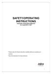
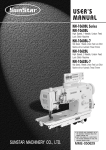
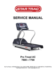
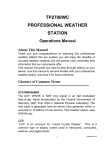
TABLE OF CONTENTS
n SECTION
o
o
o
o
o
o
o
o
o
o
o
o
3:
WIRING D I A G R A M
4:
CONSOLE ENGINEERING MODE GUIDE
JET7000 (OLD) ENGINEERING MODE GUIDE.....................................4-1
JET7000 (OLD) TOTAL "TIME" & "DISTANCE" INSTRUCTION..........4-2
JET6000/7000N ENGINEERING MODE GUIDE....................................4-3
JET7000E ENGINEERING MODE GUIDE..............................................4-4
n SECTION
o
IMPORTANT SAFETY INSTRUCTIONS
WIRING DIAGRAM (TERMINAL END, CE)............................................3-1
WIRING DIAGRAM (TERMINAL END)....................................................3-2
WIRING DIAGRAM (MCB)......................................................................3-3
n SECTION
o
2:
GROUNDING INSTRUCTIONS...................................................................2-1
POWER VOLTAGE INSTRUCTIONS...........................................................2-1
n SECTION
o
MAINTENANCE PROCEDURE
MAINTENANCE CHECK LIST..................................................................1-1
TENSIONING THE BELT PROCEDURE..................................................1-2
DECK RE-WAXING PROCEDURE.............................................................1-3
CLEAN THE GROOVES PROCEDURE....................................................1-4
n SECTION
o
1:
5:
MCB LED INSTRUCTIONS
MCB LED INDICATION.............................................................................5-1
PWM MCB LED CHART..............................................................................5-2
MCB LED TROUBLESHOOTING CHART..............................................5-3
Revision: 1.0
Date: 2001-06-01
TABLE OF CONTENTS
n SECTION
o
o
o
o
o
o
o
o
o
o
o
o
o
o
o
o
o
o
o
o
o
o
o
o
7 :
PARTS REPLACEMENT
RUNNING BELT / DECK / ROLLER......................................................7-1
MOTOR......................................................................................................7-2
INCLINE MOTOR (JET6000).................................................................7-3
CONSOLE CABLE (JET6000)...............................................................7-4
MOTOR BEARINGS & CARBON BRUSH............................................7-5
GEAR MOTOR (JET7000 SERIES).......................................................7-6
CONSOLE CABLE (JET7000 SERIES).................................................7-7
CONSOLE CONTROL BOARD............................................................7-8
KEY-PAD...............................................................................................................7-9
ELEVATION RACK (JET7000/N)............................................................7-10
CHAIN (JET7000/N)...............................................................................7-11
n SECTION
o
TROUBLESHOOTING
NO DISPLAY ON CONSOLE...............................................................6-1
RUNNING SPEED IS NOT STABLE...................................................6-2
TREADMILL STARTS TO RUN BY ITSELF........................................6-3
ALL OR SOME OF KEYS ON CONSOLE DO NOT WORK...............6-4
NOISE GENERATED UNDER MOTOR COVER.................................6-5
TREADMILL WILL NOT START...........................................................6-6
HEART-RATE-CONTROL FUNCTION DOES NOT WORK...............6-7
TREADMILL WILL NOT INCLINE UP OR DOWN............................6-8
TREADMILL WILL INCLINE UP OR DOWN BY ITSELF..................6-9
TREADMILL VARIES THE SPEED BY ITSELF...................................6-10
ERROR MESSAGE ON CONSOLE.......................................................6-11
n SECTION
o
6:
8:
SERVICE FORM
MCB LED STATUS REPORT..................................................................8-1
FIELD FAILURE REPORT......................................................................8-2
PARTS ORDER FORM.............................................................................8-3
WARRANTY CLAIM FORM.....................................................................8-4
Revision: 1.0
Date: 2001-06-01
SECTION 1
MAINTENANCE PROCEDURE
Revision: 1.0
Date: 2001-06-01
PREVENTIVE MAINTENANCE SCHEDULE
JOHNSON TREADMILL
Item
Daily
Weekly
Monthly Quarterly Biannual Annual
Console Mounting
Bolts
Frame
Inspect
Clean
Inspect
Clean
(Vacuum)
Running Belt Top
Inspect
#3 Carbon Brush
Inspect
Power Cord
Inspect
Display Console
Clean
Handlebar
Clean
Inspect
Inspect
Handrail &
Handlebar
Inspect
Front Roller
Clean
Rear Roller
Emergency Button
Replace
Inspect
Inspect
Test
Tension Wheel
Inspect
V Belt
Clean
Inspect
Inspect &
Re- waxing
Deck Re-waxing
Running Belt
Inspect
Control Box
Clean
(Vacuum)
Motor
Clean
1-1
Revision: 1.0
Date: 2001-06-01
TENSIONING THE BELT
Caution:
Running Belt:
Over-tightening of
the roller will
severely shorten the
life of the belt and
may cause further
damage to other
components.
If when you plant your foot on the belt, you can
feel a slipping sensation then the belt has stretched and
is slipping across the rollers. This is a normal and
common adjustment on a new treadmill. To
eliminate this slipping, tension both the rear rollers
Allen bolts 1/4 TURN as shown above. Try the
treadmill again to check for slipping. Repeat if
necessary, but
NEVER
TURN the
roller bolts
more than 1/4
turn at a time.
Perfe ct Tension o f Running Belt:
0.6~0.9 lbs
Drive Belt:
If you
have
tensioned the
running belt
and are still
experiencing
a slipping, adjust the tension screw. Then try the
treadmill again to check for slipping.
Perfe ct Tension of D rive Belt:
1-2
65kgw
Revision: 1.0
Date: 2001-06-01
DECK RE-WAXING PROCEDURE
Frequency:
Procedure:
Every 1 month.
1. After removing the running belt, clean the deck and
belt by using a clean towel.
2. Place the (new) running belt.
3. Place some wax on the deck about 10 cm from the edge,
in such that the wax is evenly distributed across the
deck.
4. Tighten the deck screws and assemble the rear roller
first, then assemble the front roller.
5. Replace the drive belt on the transmission pulley by
turning the Flywheel clockwise by using left hand and
use right hand to push the drive belt on to grooves of
the front roller pulley.
6. Install the front / rear rollers. Adjust the roller fixed
bolts to center the running belt at speed 4mph (6.4kph).
7. Turn on the power and then press the start key, then
hold down the fast key until the window indicates 2
mph (3 kph) and then step on the belt for 5 minutes
to ensure the wax has been evenly distributed
underneath the belt.
WAX
Name: CHRIS
Content:
TIAN
SUNWAYLUBE 1180
Viscosity Grade
68
Viscosity @40C
68.0
@100C 9 . 1
Viscosity Index
100
Pour Point, C
12
Flash Point, C
216
1-3
Revision: 1.0
Date: 2001-06-01
CLEAN THE GROOVES PROCEDURE
Frequency:
Procedure:
Every 3 months.
1 Remove the drive
belt and check the
grooves in belt for
dirt or dust and clean
it.
If dirty grooves in the drive belt, motor and roller pulley, there will
be noises while running.
2 Check the
grooves in motor
pulley for dirt or dust
and clean it.
3
Check the
grooves in roller
pulley for dirt or dust
and clean it.
1-4
Revision: 1.0
Date: 2001-06-01
SECTION 2
IMPORTANT SAFETY INSTRUCTIONS
Revision: 1.0
Date: 2001-06-01
IMPORTANT SAFETY INSTRUCTIONS
Note:
This product must
be grounded
When using an electrical product, basic precautions should
always be followed, including the following:
GROUNDING INSTRUCTIONS
WARNING:
Connect this appliance
to a properly
grounded outlet only.
See grounding
Instructions.
This product must be grounded. If it should malfunction or
breakdown, grounding provides a path of least resistance for
electrical current to reduce the risk of electrical shock. This
product is equipped with a cord having an equipment-grounding
conductor and a grounding plug. The plug must be plugged
into an appropriate outlet that is properly installed and grounded
in accordance with local codes and ordinances.
DANGER - Improper connection of the equipmentgrounding conductor can result in a risk of electric shock.
Check with a qualified electrician of serviceman if you are in
doubt as to whether the product is properly grounded. Do
not modify the plug provided with the product - if it will fit
the outlet, have a proper outlet installed by a qualified
electrician.
Note:
Power voltage 110v model:
95v ~ 140v
Power voltage 220v model:
POWER VOLTAGE INSTRUCTIONS
Power voltage 110v model: 95v ~ 140v
220v model: 210v ~ 250v
210v ~ 250v
2-1
Revision: 1.0
Date: 2001-06-01
SECTION 3
WIRING DIAGRAM INSTRUCTION
Revision: 1.0
Date: 2001-06-01
WIRING DIAGRAM (TERMINAL END, CE)
Ø I1-----A2
Ø E1-----B1
Ø I2-----A3
Ø E2-----Ground
Ø A1-----C1
Ø E3-----D2
Ø A4-----C2
Ø B2-----D4
Ø C3-----AC1 of MCB
Ø D1-----I3
Ø C4-----AC2 of MCB
Ø D3-----I4
Ø I5-----Ground
3-1
Revision: 1.0
Date: 2001-06-01
WIRING DIAGRAM (TERMINAL END)
Ø E1-----B1
Ø E2-----GROUND
Ø E3-----D2
Ø D4-----B2
Ø D1-----AC1 of MCB
Ø D3-----AC2 of MCB
3-2
Revision: 1.0
Date: 2001-06-01
WIRING DIAGRAM (MCB)
Ø A1-----Motor wire (red)
Ø A2-----Motor wire (black)
Ø P1-----V.R. wire (except the JET7000E)
Ø P2-----Sensor wire
Ø P3-----8-pin console cable
Ø P4-----6-pin console cable
Ø UP-----Incline (yellow) (except the JET7000E)
Ø Down-----Incline (white) (except the JET7000E)
Ø ELEV. COMMMON-----Incline (black) (except the JET7000E)
Ø AC1-----CE(C3 of Capacitor) Non CE(D1 of On/Off switch)
Ø AC2-----CE(C4 of Capacitor) Not CE(D3 of On/Off switch)
3-3
Revision: 1.0
Date: 2001-06-01
SECTION 4
CONSOLE ENGINEERING MODE GUIDE
Revision: 1.0
Date: 2001-06-01
JET-7000 (Old) Console Engineering Mode Guide
I.
To set up the
system
parameters:
1 Press Slow, Down, and RESET keys
simultaneously to enter Engineering Mode.
2 While the display read "CAL-HI", press PROGRAM
INTERVAL. The display will show C1. Please
press Fast or Slow keys to set C1, and then press
Up key to set C2-C6.(refer to table 1)
parameter value memo
C1
35
For ver0.3 35(British) 51(metric)
C2
125
C3
66
C4
50
C5
4
C6
1-89
Only for ver 0.3 max time
Table 1
3 Press POWER key to save.
II.
To calibrate
the elevation .
u (from 0 to 15%)
1. Press Slow , Down, and RESET keys
simultaneously. And the display reads "CAL-HI".
2. While the treadmill raises to the maximum incline,
verify the grade should be 15% (30cm).
3. Press the START/STOP key, and the display reads
"CAL-LO".
4. While the treadmill lower to the minimum incline,
verify the grade should be 0% (8~9cm). Press the
START/STOP key to store.
4-1
Revision: 1.0
Date: 2001-06-01
Console Engineering Mode Guide
JET-7000 (Old)
u If the distance between the front bottom edge of the
frame and the floor does not meet the specifications
either at the maximum or minimum incline, you have
to adjust the location of the related limit switch to
calibrate the incline to Spec.
III.
To calibrate the
speed.
IV. (Old Version)
To choose
metric or
British
mode.
(New Version)
To choose
metric or
British mode.
1. Press Slow, Down, and RESET keys
simultaneously.
2. While the display reads "CAL-HI", press Up
key. Then the display shows "SLO".
3. Read the real speed from the window of "TIME". (The
speed value on the "TIME" window is in British
System only)
4. Using the Fast or Slow keys to adjust the speed of the
treadmill to 0.5mph (0.8kph). Then press
START/STOP key, and the display shows "FAS".
5. Using the Fast or Slow keys to adjust the speed of the
treadmill to 12.4mph (20.0kph).
6. Press to START /STOP key to store.
(OLD):
Hold down SAFETY and POWER keys, then
remove SAFETY key then the display shows "Si" or "bri".
u If you want the metric mode, you must remove
POWER key when the display shows "Si".(the British
mode ê "bri") Then the display shows "bye" briefly,
and reset itself.
(NEW): Hold down SAFETY, PROGRAM
INTERVAL and RESET keys, then remove SAFETY
key then the display shows "Si" or "bri".
u If you want the metric mode, you must remove
PROGRAM INTERVAL and RESET keys when the
display shows "Si".(the British mode ê "bri") Then
the display shows "bye" briefly, and reset itself.
(Except the ver 0.3)
4-1
Revision: 1.0
Date: 2001-06-01
Total "TIME" & "DISTANCE" Instruction JET-7000 (Old)
When you press Safety key and release (for ver 0.3, press down FAST & UP key)
then, the display shows:
TIME-WINDOW HEART RATE-WINDOW DISTANCE/CALORIES
XXXX
XX
XXX
SPEED/INCLINE
XX
u The content in the TIME-WINDOW indicates the accumulated running hours of
the treadmill.
u The content in the HEART RATE & DISTANCE/CALORIES-WINDOW
indicate the accumulated running miles (in British system only) of the treadmill.
u The content in the SPEED/INCLINE-WINDOW indicates the version of
software.
e.g.
u TOTAL TIME: 51 hours
u TOTAL DISTANCE: 2325 miles
u SOFTWARE VERSION: 0.1
4-2
Revision: 1.0
Date: 2001-06-01
Console Engineering Mode Guide
1.
2
3
JET-6000/7000NEW
Holding “UP” & “SLOW” keys simultaneously about 5 seconds to enter Engineering
Mode.
The Display will be showed "P6". Press “SELECT” key then press “SLOW” or
“FAST” to set metric(kph) or British(mph). Press “SELECT” key to store.
Press “DOWN” key to reach the “P0” address. Then press “SELECT” key for setting
the “P0” parameter (refer to “DISTANCE’ window”). Press “FAST” OR ‘SLOW’ key
to adjust speed When the speed display 0.5mph(0.8kph) on “SPEED” window then
press “SELECT’ key to store.
Follow the step 3 for setting the “P1”(12mph, 19.2kph) and “P2”(6mph, 9.6kph).
Press “UP” key to reach “P5” address, press “SELECT” key. Then press “FAST” key
until the deck raise to the max incline. Then press “SELECT’ to store.
6 Press “DOWN” key to reach “P4” address, press the “SELECT” key. Then press
“SLOW” key until the deck lowers to min incline. Press “SELECT’ key to store.
7 Press “UP” key to reach “P7” address, press “SELECT” key. Then press “SLOW” or
“FAST” key to adjust the values to "99". Press the “SELECT” key to store.
8 Press “UP” key to reach “P8” address, press “SELECT” key. Then press “SLOW” or
“FAST” key to input your weight. Press the “SELECT” key to store.
9 Press “UP” key to reach “P9” address, press “SELECT” key. Then you can see the total
running hours of the treadmill.
10 Press “UP” key to reach “P10” address, press “SELECT” key. Then you can see the
total running distance of the treadmill.
4
5
u Remark:
1
2
Hold down the “UP” and “DOWN” key about 5 seconds to reset under the “P9” or
“P10”.
Holding the “START” key about 5 seconds to reset the P0 P1 P2 P4 P5 in “P7” of
engineering mode.
u Define the parameters:
P0 … .Min. Speed
P1 … .Max. Speed
P2 … .Mid. Speed
P3 … .None
P4 … .Min. Slope
P5 … .Max. Slope
P6 … .Unite mode
P7 … .Max. Time
P8 … .User Weight
P9 … .Total RunningTime P10...Total Running Distance
4-3
Revision: 1.0
Date: 2001-06-01
Console Engineering Mode Guide JET-7000E
1
2
3
4
5
6
7
8
9
Press “SLOW”, “STOP” keys simultaneously about 5 seconds to enter Engineering
Mode.
The Display will be showed "P6". Press “SELECT” key then press “SLOW” or
“FAST” to set metric(kph) or British(mph). Press “SELECT” key to store. Press
“STOP” key for next parameter setting
Press “SLOW” key to reach the “P0” address. Then press “SELECT” key for setting the
“P0” parameter (refer to “DISTANCE’ window”). Press “FAST” OR ‘SLOW’ key to
adjust speed When the speed display 0.5mile(0.8km) on “SPEED” window then press
“SELECT’ key to store. Press “STOP” key for next parameter setting
Follow the step 3 for setting the “P1”(12mph, 20kph) and “P2”(6mph, 10kph).
Press “FAST” key to reach “P7” address, press “SELECT” key. Then press “SLOW” or
“FAST” key to adjust the values to "99". Press the “SELECT” key to store. Press
“STOP” key for next parameter setting
Press “FAST” key to reach “P8” address, press “SELECT” key. Then press “SLOW” or
“FAST” key to input your weight. Press the “SELECT” key to store. Press “STOP”
key for next parameter setting
Press “FAST” key to reach “P9” address, press “SELECT” key. Then you can see the
total running hours of the treadmill. Press “STOP” key for next parameter setting
Press “FAST” key to reach “P10” address, press “SELECT” key. Then you can see the
total running distance of the treadmill. Press “STOP” key for next parameter setting
Press the Safety Key to finish.
u Remark:
1
2
Holding the “FAST” and “SLOW” key about 5 seconds to reset the accumulated in “P9”
or “P10” of engineering mode
Holding the “START” key about 5 seconds to reset the P0 P1 P2 in “P7” of engineering
mode.
u Define the parameters:
P0 … .Min. Speed
P1 … .Max. Speed
P2 … .Mid. Speed
P3 … .None
P4 … .None
P5 … .None
P6 … .Unite mode
P7 … .Max. Time
P8 … .User Weight
P9 … .Total RunningTime P10...Total Running Distance
4-4
Revision: 1.0
Date: 2001-06-01
SECTION 5
MCB LED INSTRUCTIONS
Revision: 1.0
Date: 2001-06-01
MCB LED Indication
When we designed the lower control board (MCB) for our
treadmills we placed status lights (LEDs) on it to aid in field
diagnosis and repair. The following is an overview of what these
indicator lights mean and what can be checked with them in the
field.
Note:
Use a multi-meter to
test the power socket.
210v ~ 250v
Note:
For PCB (Upperboard)
115VAC
Light - When lit, this indicates that
the MCB has power applied. If this
LED is off, check connections, power switch position, fuses and
circuit breakers. If the AC light is not lit, the MCB will not
operate.
+12V
Light- when lit, this indicates the presence of
the regulated 12-volt direct current supply
necessary for the operation of the PCB. If dim the supply voltage
may be marginal and if out not present or inadequate. If the light
is not lit, the console will not operate. If the AC light is lit and
the +12V light is not, check for shorted cabling or a defective
upper console.
5-1
Revision: 1.0
Date: 2001-06-01
MCB LED Indication
Note:
Motor power
MOTOR
Light- When lit, indicates the Start
key has been pressed and the K1 relay
has been activated, which will then allow the AC power to be present
to the control board with the two big capacitors on it. If the MOTOR
light is not lit after the Start key has been pressed, check the keypad,
the 8-pin cable and the interconnection of the wiring mentioned
above. If the problem persist, return the board to JMI.
ILT1/ILT2
Note:
Light- When ILT1 is lit, indicates
uover 25 +- 3 Amps
the current to the motor is under 25
when ILT2 is lit
+- 3 Amps. When ILT2 is lit, indicates the current to the motor has
uunder 25+- 3 Amps reached the peak current trip point of 25 +- 3 Amps. The MCB
when ILT1 is lit
might be broken down if the over-current situation persists for a
while. It is recommended that the treadmill should be thoroughly
If ILT1 is not lit,
examined for wear or damaged components, which might have lead
check the fuse.
to the extended current limit condition. Besides, treadmill might have
to be re-waxed at this time.
M.C.SIG
Note:
A control
command from the
PCB to the MCB
Light- Indicates the control PWM
from the PCB is present. It will
blink at the control frequency used by the PCB when the PCB
commands speed. If the control signal should exceed 95 percent
duty cycle, the PWM light shuts off and sets the MCB to a safe
shutdown mode. In the event this should occur, the power to the
treadmill should be removed, the cabling checked for shorts and the
PCB replaced. If this problem persists, replace the MCB.
5-1
Revision: 1.0
Date: 2001-06-01
MCB LED Indication
Note:
The incline is being
commanded up
Note:
The incline is being
commanded down
Note:
RPM signal from the
speed sensor-magnet
pair.
UP
Light- Indicates the PCB is commanding the incline
gear to move up. If the User is commanding the incline
to increase and this light is not lit, check cabling, verify proper PCB
operation and replace it if either is defective. If the problem
persists, replace the MCB. If the light is lit but the incline is not
moving, check and verify incline gear and its connection to the
board. If this problem persists replace MCB.
DN
Light- Indicates the PCB is commanding the incline
gear to move down. If the User is commanding the
incline to decrease and this light is not lit, check cabling, verify
proper PCB operation and replace it if either is defective. If the
problem persists, replace the MCB. If the light is lit but the incline
is not moving, check and verify incline gear and its connection to
the board. If this problem persists replace MCB.
SPEED
Light- Indicates the MCB is receiving
the revolution signal from the speed
sensor-magnet pair. If this light is not lit, verify the speed sensor
(reed switch) and magnet installed in the front roller. If this
problem persists, replace MCB.
5-1
Revision: 1.0
Date: 2001-06-01
PWM MCB LED CHART
NO.
115V
+12V
AC
MTR
ILT1
ILT2
M.C.SIG
UP
DOWN
1
OFF
OFF
OFF
OFF
OFF
OFF
OFF
OFF
2
ON
OFF
OFF
OFF
OFF
OFF
OFF
OFF
3
ON
OFF
ON
OFF
OFF
OFF
OFF
OFF
4
ON
ON
OFF
OFF
OFF
OFF
OFF
OFF
5
ON
ON
OFF
OFF
OFF
OFF OR
BLINKING
N/A
N/A
6
ON
ON
ON
OFF
ON and
OFF
BLINKING
N/A
N/A
N/A
N/A
7
ON
ON
ON
ON
OFF
COMES ON
BRIEFLY &
THEN SHUTS
OFF
8
ON
ON
ON
ON
OFF
N/A
ON
OFF
9
ON
ON
ON
ON
OFF
N/A
ON
OFF
10
ON
ON
ON
ON
OFF
N/A
OFF
ON
11
ON
ON
ON
ON
OFF
N/A
OFF
ON
5-2
Revision: 1.0
Date: 2001-06-01
MCB LED-AIDED TROUBLESHOOTING CHART
NO
.
PROBLEM/RESULT
CORRECTIVE ACTION
1 No operation of MCB or PCB
Verify connections, power switch and circuit
breaker.
2 No operation of MCB or PCB
Replace MCB
3 PCB will not power up
Replace MCB
Verify adequate line voltage. If line voltage is
4 PCB will power up but the MCB adequate, MCB is damaged and needs to be
will not operate
returned to manufacturer.
5 Will not operate the motor
Verify connections to the P3 and the keypad. If the
connections look good, verify the 8-pin cable and
the keypad. If problem still persist, replace the
MCB.
6 MCB in current limit mode
The MCB is experiencing a discontinuous over
current events. Check for mechanical wear and/or
defective motor. If on mechanical wear and motor
good, replace MCB and return defective MCB to
manufacturer.
7 Will not operate the motor
Check and verify the P3 and P4 cables are good,
replace the PCB. If the problem persists, replace
the MCB.
8 Incline move up
9 Incline does not move
Verify connections to the P3 & incline motor. If the
connections look good, replace MCB, PCB.
10 Incline move down
11 Incline does not move
Verify connections to the P3 & incline motor. If the
connections look good, replace MCB, PCB.
5-3
Revision: 1.0
Date: 2001-06-01
SECTION 6
TROUBLESHOOTINGS
Revision: 1.0
Date: 2001-06-01
No display on console
Possible causes:
1. Breaker is damaged.
2. ON/OFF switch is
damaged.
Fix:
1. ( refer to MCB LED layout & indication) Verify if
LED 115vAC(AC) is lit. If this LED is lit, go to step 2.
If LED 115vAC(AC) is not lit, verify the following:
A
B
3. MCB is damaged.
4. 8-pin console cable is
damaged.
u
5. PCB is damaged.
Inspect the circuit breaker to see if it has tripped off.
( If it is tripped off--like diagram B, reset the
breaker. And check which part is short-circuited.
Then replace the short-circuited
part.)
2. The switch is turned to the "ON"
position.
( If the switch light isn't lit, replace the switch.)
u
Verify wire connection AC1 & AC2 on the MCB.
( refer to wiring diagram )
u
Verify the ON/OFF switch, breaker & socket wires are
connected.
3. Verify if LED +12v is lit. If one is not lit, replace MCB.
4. Replace 8-pin console cable.
5. Replace PCB.
6-1
Revision: 1.0
Date: 2001-06-01
Running speed is not stable
Possible causes:
1. AC power voltage is
too low.
Fix:
1. Check the power voltage by using voltage-meter to
2. Tension of drive belt
or running belt is too
loose.
3. Poor adjustment of
MCB.
4. MCB is damaged.
see if it is within 120V+-15% or 230V+-15%.
u If the power voltage isn't within the range, look
for a qualified electrician for help.
5. Motor is damaged.
2. Open the motor cover, if the belt has stretched and is
slipping across the rollers when running.
u Adjust the belt tension.
3. Remove the motor cover and run the machine at low
speed, the adjust the IR COMP of MCB.
u If it hasn't been improved, replace new MCB.
4. Replace new motor.
6-2
Revision: 1.0
Date: 2001-06-01
Treadmill starts to run by itself
Possible causes:
Fix:
1. The console cable is
broken.
1. Replace the console cable with a new one.
2. Replace the PCB.
2. PCB is out of order.
3. Replace the MCB.
3. MCB is out of order.
6-3
Revision: 1.0
Date: 2001-06-01
All or some of the keys on console do not work
Possible causes:
1. Keypad connecting
plug is not fit-in
properly.
Fix:
1. Disconnect the keypad and replace the keypad,
and check again.
2. Replace the keypad.
2. Keypad is damaged.
3. PCB is damaged.
3. Replace the PCB.
6-4
Revision: 1.0
Date: 2001-06-01
Noises generated under motor cover
Possible causes:
1. The running belt
tension is adjusted too
tight.
Fix:
1. Adjust the belt tension so that the belt does not
start slipping and then check if the noise has
disappeared.
2. The bearing of front
roller is not installed
correctly.
3. Dirty grooves of drive
belt.
4. The motor is
damaged.
5. Dust in the rack.
(JET-7000)
u Let the treadmill run, without using it, for at
least 5 days because sometimes the bearing will
settle and become quiet then check if the noise
has disappeared.
2. Replace the front roller with a new one to see if the
noise disappear.
3. Remove drive-belt and check the grooves in belt
for dirt or dust and clean if necessary. Clean also
the motor pulley and the roller pulley grooves and
check if the noise has disappeared.
4. The motor bearing is damaged.
(Refer to "motor bearings replacement
procedure")
u Replace the motor.
5. (JET-7000): Remove the rack cover and check the
rack. for any dust.
u Clean the rack
6-5
Revision: 1.0
Date: 2001-06-01
Treadmill will not start
Possible causes:
1. MCB is damaged.
Fix:
2. 6-pin console cable
is damaged.
Open motor cover, verify wire connection A1 and A2
(motor wire) on the MCB then plug in the power cord
and turn on the power switch. Then press “POWER,
START, FAST“ buttons.
3. PCB is damaged.
1. Verify the LED indicator of MOTOR is lit.
If that LED MOTOR is not lit, replace MCB.
4. Motor is damaged.
2. Verify if LED M.C.SIG is lit. (If it is not lit,
replace 6-pin console cable.)
3. If LED M.C.SIG is still not lit, replace PCB.
4. Replace Motor.
6-6
Revision: 1.0
Date: 2001-06-01
Heart-Rate-Control function does not work
Possible causes:
1. Transmitter does not
contact with user's
chest very well.
2. Transmitter(Polarbelt) is at low battery
status.
3. Transmitter(Polarbelt) is damaged.
4. Heart-rate-control
board is damaged.
5. PCB is damaged.
Fix:
1. Center the
transmitter on your
chest below the
pectoral muscle(breast)
as shown, then check again.
2. Remove the battery cover of the transmitter.
Replace a new battery and check again.
u Actually, as moisture may activate the
transmitter, please dry transmitter after use.
OR
3. Transmitter is damaged.
Replace the Transmitter.
OR
4. Heart-rate-control board is damaged.
Replace the Heart-rate-control board.
OR
5. PCB is damaged.
Replace the PCB.
6-7
Revision: 1.0
Date: 2001-06-01
Treadmill will not incline up or down
Possible causes:
1. The incline settings
are not correct.
Fix:
1. Enter to Engineering Mode to see if the incline
motor will be activated.
u
OR
Use a new 8-pin console cable to connect
PCB and MCB to see if the incline motor will
be activated.
4. MCB is damaged.
u
OR
Replace PCB.
5. Variable Resistance
is damaged.
u
OR
Replace MCB.
2. The 8-pin console
cable is damaged.
3. PCB is damaged.
2. Enter to Engineering Mode and verify if the
number in the right window varies as the elevation
changes.
u
OR
Ø
Replace 8-pin cable and check.
Ø
Replace Variable Resistance.
Ø
Replace PCB and check.
u Enter the Engineering Mode to re-calibrate the
incline.
6-8
Revision: 1.0
Date: 2001-06-01
Treadmill will incline up or down by itself
Possible causes:
1. The 8-pin console
cable is damaged.
Fix:
2. MCB is damaged.
1. Use a new 8-pin console cable to connect PCB to
MCB. Then turn the power on, press "POWER,
START, UP, DOWN" keys to see if this fix the
problem.
3. PCB is damaged.
2. Replace MCB
4. Grounding of the
treadmill is poor
3. Replace PCB.
4. Each component shall be properly grounded to the
frame and the frame shall be earthed through the
third prone pin of the power socket.
6-9
Revision: 1.0
Date: 2001-06-01
Treadmill varies the speed by itself
Possible causes:
1. Keypad is stuck.
Fix:
1. Remove the keypad and verify the keypad is stuck.
If it is stuck, replace with a new keypad.
2. PCB is damaged.
3. Grounding
2. If speed or incline still changes by itself, replace
the PCB and refer to "Engineering Mode Guide" to
re-program all the parameters.
3. Each component shall be properly grounded to the
frame and the frame shall be earthed through the
third prone pin of the power socket.
Remarks: The symptom here is the speed indication
on the console will vary with the speed.
6-10
Revision: 1.0
Date: 2001-06-01
Error message on console
JET6000/7000N
Error
message
Err2
cause
solution
P0 P1 P2 P4 P5 have a wrong
parameter values
l
Re-calibrate all parameter
values in Engineering Mode
•Re-plug or replace the Incline
Motor(Jet6000)
• Re-plug or replace the
Err3
VR is open loop or short
VR(Jet7000)
•Re-plug or replace the 8-pin
console cable
•MCB or PCB is damaged
Err6
No elevating after press the “up”
or “down” key about 5 seconds
l
Re-calibrate the “P4, P5”
parameter values.
JET7000E
Error
message
Err2
cause
solution
EEPROM Checksum error
6-11
l
Re-calibrate all parameter
values in Engineering Mode
Revision: 1.0
Date: 2001-06-01
SECTION 7
PARTS REPLACEMENT PROCEDURE
Revision: 1.0
Date: 2001-06-01
RUNNING BELT/DECK/ROLLER REPLACEMENT
Tools required:
Procedure:
ü Philips screwdriver
1. Remove the screws
from the front cover
by using the
screwdriver.
ü T-handle key
(8mm,5mm)
2. Remove two rear
covers from the end of
the side rails.
3. Pull out the two
side rails.
4. Elevate the
machine to a proper
height for removing
the front roller.
7-1
Revision: 1.0
Date: 2001-06-01
RUNNING BELT/DECK/ROLLER REPLACEMENT
Tools required:
Procedure:
ü Philips
screwdriver
5. Turn the flywheel
counterclockwise by using
your left hand and pull out
the drive belt from the
wheel by using your right
hand.
ü T-handle key
(8mm,5mm)
6. Remove the bolts from
the front and rear rollers
by using the T-handle key
(8mm).
7. Remove the front roller,
drive belt and rear roller.
(If replacing the roller, go to
step 13.)
8. Remove the 8 screws
holding the deck to the frame
then remove the deck with the
running belt. (If replacing
the running deck, go to step
12.)
9. Remove the deck
extension with screwdriver.
10. Flip and rotate the deck and tighten the deck extension, then
install a new running belt.
11. Refer to "REWAXING THE DECK PROCEDURE" for how
to lubricate the deck. Or, skip this step if replacing the deck.
(Go to step 14.)
7-1
Revision: 1.0
Date: 2001-06-01
RUNNING BELT/DECK/ROLLER REPLACEMENT
Tools required:
Procedure:
ü Philips screwdriver
12. Replace the deck and put the old running belt through
the deck and place the deck with the running belt on
the frame. (Go to step 14.)
ü T-handle key
(8mm,5mm)
13. Replace the front roller and rear roller. (Go to step 15.)
14. Tighten the deck screws.
15. Assemble the rear roller first, then assemble the front
roller.
16. Place the drive belt on the transmission pulley by
turning the flywheel clockwise by using left hand and
place the drive belt on to grooves of the front roller
pulley by using your right hand.
17. Install the front / rear rollers. Adjust the running belt
tension bolts to center the running belt at high speed.
18. Try to step on the belt to check if the belt slips.
19. Install the side rails and secure the end covers.
20. Install the front cover and secure the screws.
7-1
Revision: 1.0
Date: 2001-06-01
MOTOR PLACEMENT
Tools required:
Procedure:
ü Philips screwdriver 1. Remove screws from the front cover by using the
screwdriver and remove it.
ü T-handle wrench
2. Remove cables connecting to the motor and lower board,
(14mm)
remove also the ground wire by using the screwdriver.
3. Remove the motor mount screws by using the T- handle
ü Ratchet Box
wrench.
Wrench (11mm)
4. Replace the motor.
5. Secure the motor mount screws (not too tight at this time
so that the tension adjustment can be made).
6. Place the drive belt on the transmission pulley, turn the
flywheel clockwise by using your left hand and place the
drive belt on to grooves of the front roller pulley.
7. Adjust the belt-tension-adjusting screw until the tension
is within 80 ~ 90lbs.
8. Tighten the motor mount screws (remark1).
9. Reconnect cables and the ground wire.
10. Turn on the power and enter the Engineering Mode to
check if the extreme speeds are within the correct range.
11. Try to step on the belt at low speed to check if the belt
slips.
12. Install the front cover and secure the screws.
Remark1: The centerline of motor shaft has to parallel
with the centerline of roller.
7-2
Revision: 1.0
Date: 2001-06-01
INCLINE MOTOR REPLACEMENT (JET6000)
Tools required:
Procedure:
ü Philips screwdriver
1. Remove screws from
the front cover by using
the screwdriver to open
the cover.
ü Wrench (14mm)
ü Wrench ( 17mm)
2. Disconnect cables from the connectors of the incline
motor and MCB and also disconnect the ground wire.
3. To prevent the frame from falling down heavily while
removing the incline motor, put a support with
proper height under the front of frame.
4. Remove the bolts and the nuts from the incline motor by
using the wrenches (14, 17).
5. Replace the incline motor with a new one.
6. Reconnect cables and the grounding wire to the
connectors and the frame.
7. Remove the support under the frame.
8. Turn on the power and enter the Engineering Mode to
check if the extreme inclines are within the correct
range.
9. Install the front cover and secure the screws.
7-3
Revision: 1.0
Date: 2001-06-01
CONSOLE CABLE REPLACEMENT (JET6000)
Tools required:
Procedure:
ü Philips screwdriver
1. Remove screws from the
motor cover by using the
screwdriver.
ü T-handle key
(5mm).
2. Remove screws from the right support with the Thandle key (5mm).
3. Remove the screws from the console cover.
4. Disconnect the console cable from the PCB and
MCB.
5. Pull out the snap bushing first then tie the old cable to
the new one with a rigid string.
6. Pull the old cable from the top end until the new
cable threads all the way through the right support
and the console bare.
7. Connect the console cable to PCB and MCB.
8. Install the console cover and tighten the screws.
9. Install the front cover and tighten the screws.
7-4
Revision: 1.0
Date: 2001-06-01
MOTOR BEARINGS & CARBON BRUSH
REPLACEMENT
Tools required:
Procedure:
ü
Nutdriver
(5/16inch)
1. Remove the screws of
carbon brush cover and the
carbon brushes with the coin.
ü
Bearing puller
2. Check the surface of carbon
ü
Woodenhammer
ü
brush if smooth.
u If the surface of carbon brush
is pitted, rough or with burn marks
replace the carbon brush.
Coin
(If replacing the carbon brush,
go to step 10.)
3. Prior to disassembling the
end caps, you must make a
mark on the end cap.
4. Use the nutdriver (5/16inch)
to remove bolts holding the end
caps to the main enclosure of
the motor.
5. Tap the shaft carefully with
a wooden hammer to remove
the end caps.
7-5
Revision: 1.0
Date: 2001-06-01
MOTOR BEARINGS & CARBON BRUSH
REPLACEMENT
Tools required:
ü
Nutdriver
(5/16inch)
ü
Bearing puller
ü
Wooden hammer
Procedure:
6. Remove the bearings of both sides by using the bearing
puller.
7. Install the new bearings to the shaft by using the wooden
hammer.
8. Put on the two end caps and use the nutdriver(5/16inch)
to lock the caps to the main enclosure.
9. Install the carbon brush and the carbon brush cover.
(The end of the procedure.)
10. Replace the carbon brush with a new one.
11. Install the carbon brush and the carbon brush cover.
12. Turn the power on, let the treadmill run for about 1 hour
at 3.0kph to allow the proper seating of the brush.
7-5
Revision: 1.0
Date: 2001-06-01
GEAR MOTOR REPLACEMENT (JET-7000 series)
Tools required:
Procedure:
ü Philips
screwdriver
1. Release screws of front
cover by using screwdriver
to open the cover.
ü T-handle key
(14mm)
ü Ratchet Box
Wrench (11mm)
2. Disconnect remove cables from the Gear motor and lower
board and also disconnect the ground wire.
3. To prevent the frame from falling down heavily while
remove the incline motor, please put the support with a
proper height (9cm) under the front end of frame.
4. Loosen the Gear motor mount screws by using T-handle
wrench (14mm) to remove the Gear motor and replace
with a new one.
7-6
Revision: 1.0
Date: 2001-06-01
GEAR MOTOR REPLACEMENT (JET-7000 series)
Tools required:
Procedure:
ü Philips
screwdriver
5. Install the chain onto main chain wheel and tighten the
fixed bolts of gear motor. Use Ratchet Box wrench
(11mm) to adjust the chain-tension-screw, which is located
at the back end of the gear, motor.
ü T-handle Wrench
(14mm)
ü Ratchet Box
Wrench (11mm)
6. Reconnect cables and ground wire by referring to the
wiring diagram. Remove the support under the frame.
7. Turn on the power and enter the Engineering Mode to
check if the extreme incline is within the correct range.
8. Install the front cover and secure the screws.
7-6
Revision: 1.0
Date: 2001-06-01
CONSOLE CABLE REPLACEMENT (JET-7000 series)
Tools required:
Procedure:
ü Philips
screwdriver
1. Remove screws from
the front cover by using
the screwdriver and
remove it.
ü T-handle key
(5mm).
2. Use the T-handle key
(5mm) to remove screws
of the left handle bar and
remove it.
3. With the screwdriver
remove the screws from
the console base plate.
4. Disconnect the console
cable from the PCB and
MCB.
5. Use the T-handle key
(5mm) to remove the
screws holding the console
base to the stanchion and
remove the console base.
7-7
Revision: 1.0
Date: 2001-06-01
CONSOLE CABLE REPLACEMENT (JET-7000 series)
Tools required:
Procedure:
ü Philips
screwdriver
ü
T-handle key
(5mm).
6. Remove the left stanchion protrusion out and pull out
both cables.
7. Install the new cable into the left stanchion protrusion.
8. Install the stanchion protrusion onto the stanchion.
9. Install the console base onto the stanchion and tighten it.
10. Install the console base plate and tighten the screws.
11. Install the left handle bar and tighten it.
12. Install the front cover and tighten the screws.
7-7
Revision: 1.0
Date: 2001-06-01
PCB REPLACEMENT
Tools required:
Procedure:
ü Philips screwdriver
1. Use screwdriver to
loosen the screws of
console base plate.
ü Nutdriver (6mm)
2. Disconnect the
console cables from
the PCB.
3. Use the Nutdriver
(6mm) to loosen the
screws holding the
PCB to the base to
remove the PCB.
4. Replace with a new PCB and tighten the screws.
5. Reconnect the cables with PCB by referring to wiring
diagram.
6. Install the console base plate.
7. Turn on the power.
Enter the Engineering Mode.
(Refer to the console engineering mode guide for
details of calibration)
7-8
Revision: 1.0
Date: 2001-06-01
KEYPAD REPLACEMENT
Tools required :
ü
Procedure:
Philips screwdriver
1. With the
screwdriver loosen
the screws from the
console base cover.
2. Disconnect the
plug of keypad from the PCB.
3. Remove the safety key and the overlay.
4. Replace with a new keypad and connect it with PCB.
5. Install the console base plate and tighten the screws.
6. Place the new overlay on the console correctly and
press it firmly on the edges.
7. Install the safety key.
7-9
Revision: 1.0
Date: 2001-06-01
ELEVATION RACK REPLACEMENT (JET-7000 series)
Tools required:
ü
Philips
screwdriver
ü
T-handle
key(5mm)
Procedure:
1. Turn on the power and keep the incline at the minimum
elevation. Then turn off the power.
2. Remove the front cover.
3. Disconnect console
cables from the MCB.
4. Use the T-handle key
(5mm) to loosen screws and
remove the stanchion
together with console base.
5. To prevent the frame from fall down heavily while
remove the elevation rack & outer pinion & rack
cover, please put a support with proper height (9cm)
under the front of frame before the replacement.
6. Loosen the screws
from the right/left rack &
pinion outer cover by
using T-handle key (5mm)
and remove the covers.
7-10
Revision: 1.0
Date: 2001-06-01
ELEVATION RACK REPLACEMENT (JET-7000 series)
Tools required:
Procedure:
ü Philips
screwdriver
ü T-handle
key(5mm)
7. Remove the elevation rack. Then remove the C clip of
the transportation wheel to remove the transportation
wheel.
8. Attach the new elevation rack on to the transportation
wheel and attach C clip, then attach the elevation rack
onto the incline gear and install the covers.
9. Remove the support .
10. Install and tighten the left / right stanchion and connect
console cables to the MCB.
11. Turn on the power and enter the Engineering Mode to
check if the minimum and maximum elevations are
within the limits.
12. Install the front cover and secure the screws.
7-10
Revision: 1.0
Date: 2001-06-01
CHAIN REPLACEMENT (JET-7000 series)
Tools required:
Procedure:
ü Philips
screwdriver
1. Turn on power and keep the incline at the minimum
elevation. Then turn off power.
ü T-handle
wrench(14mm)
2. Remove the front cover.
ü Ratchet Box
Wrench (11mm)
3. To prevent the frame from falling down heavily while
replacing the chain, please put a support with proper
height (9cm) under the front of frame before
replacement.
4. Release the Gear motor mount screws by using the Thandle wrench (14mm) and loosen the chain-tensionadjusting screw by using a Ratchet Box wrench (11mm).
7-11
Revision: 1.0
Date: 2001-06-01
CHAIN REPLACEMENT (JET-7000 series)
Tools required:
Procedure:
ü Philips
screwdriver
ü T-handle
wrench(14mm)
ü Ratchet Box
Wrench (11mm)
5. Remove the chain latch to separate and then take out the
chain.
6. Install the chain onto main chain wheel in such the way
that the minimum elevation control dog touches the
minimum elevation limit switch.
7. Install the chain latch.
8. Adjust the chain tension, then tighten the Gear motor
mount screws by using T-handle wrench (14mm).
9. Turn on the power and enter the Engineering Mode to
check if the minimum and maximum elevations are
within the range.
10. Install the front cover and secure the screws.
7-11
Revision: 1.0
Date: 2001-06-01
SECTION 8
SERVICE FORM
Revision: 1.0
Date: 2001-06-01
MCB LED Status Report
Product Type :...............................
Serial Number :........................
When power-up the treadmill the MCB LED status is :
AC(*115V)Light
18V Light
LED On :
LED On :
LED Off :
LED Off :
MTR Light
11(*12)V Light
LED On :
LED Off :
I-Limit Light
LED On :
LED On :
LED Off :
LED Off:
PMW Light
LED blinking:
LED Dim:
LED Off :
*ILT1 Light (JET7000)
* ILT2 Light (JET7000)
LED On :
LED On :
LED Off:
LED Off :
When you press the UP or DOWN key, the LED status is :
Up Light
Dn Light
LED On :
LED On :
LED Off:
LED Off :
*These LEDs are only for JET-7000 MCB
In order to fill-out this Report properly please use the PWM MCB CHART and MCB LEDaided troubleshooting which you can find in the Service Manual.
Please fill-out this Report at the moment before repairing the problem.
Serial number * MCB : .......................................
Reported by : ...............................
Approximate hours of use : .......................................... Company Name : ................................
8-1
Revision: 1.0
Date: 2001-06-01
Field Failure Report
Name of Distributor : … … … … … … … …
Report # … … … … … … … ......
Warranty
Failure ( ) Intermittent
( ) Persistent
(
) Yes ( ) No
Product : … … … … … … … … …
Serial number: … … … … … … . .
Failure Symptom : ( Pls refer to the service manual for the symptom of failure. )
… … … … … … … … … … … … … … … … … … … … … … … … … … … … … … ….
… … … … … … … … … … … … … … … … … … … … … … … … … … … … … … ….
… … … … … … … … … … … … … … … … … … … … … … … … … … … … … … ….
Cause of Failure :
… … … … … … … … … … … … … … … … … … … … … … … … … … … … … … ….
… … … … … … … … … … … … … … … … … … … … … … … … … … … … … … ….
… … … … … … … … … … … … … … … … … … … … … … … … … … … … … … ….
Parts Replaced
*:
Suggestions to prevent Failure :
… … … … … … … … … … … … … … ..
… … … … … … … … … … … … … … ..
… … … … … … … … … … … … … … ..
… …. … … … … … … … … … … … ….
… …. … … … … … … … … … … … ….
… …. … … … … … … … … … … … ….
*When parts needed please fill out a Parts Order Form as detailed as possible.
Date :
Place :
… … … … ….
……… … … …
Prepared By :
…… … … … …
8-2
Company Stamp :
.… … … … … … ….
Revision: 1.0
Date: 2001-06-01
Parts Order
Distributor: … … … … … … ........ …..
Order # … … … … … … … … … … …
Delivery Terms:
( ) CIP ..................... Delivery Address:
( ) FCA
( ) FOB
.......................................................
.......................................................
.......................................................
.......................................................
Warranty ( ) Yes
( ) No
Product
Serial number
...........................................................
...........................................................
...........................................................
...........................................................
........................................................
........................................................
........................................................
........................................................
Product
Drawing #
Part Number
Part Name
Qty
...................... .................... ........................... .............................. .............
...................... .................... ........................... .............................. .............
...................... .................... ........................... .............................. .............
...................... .................... ........................... .............................. .............
...................... .................... ........................... .............................. .............
...................... .................... ........................... .............................. .............
...................... .................... ........................... .............................. .............
...................... .................... ........................... .............................. .............
Remark: Please refer to the spare part kit for all the information that are to be filled out above.
Date
Place
Signature
............................
............................
.....................................
8-3
Company Stamp
Revision: 1.0
Date: 2001-06-01
Warranty Claim Form
Claim no: ........................
Dealer Name: ..................................................
MODEL
SERIAL NUMBER
Page .......... of ...........Pages
DESCRIPTION OF DEFECT
PARTS #
QTY
AUTHORIZED BY: ..............................
8-4
Revision: 1.0
Date: 2001-06-01