1
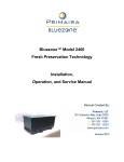
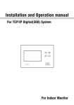
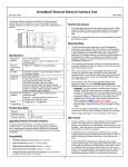
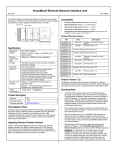
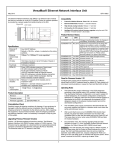
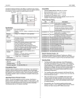
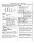
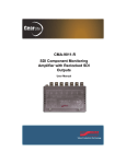
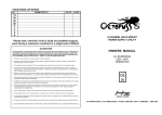
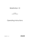
Bluezone® Model 2400-014 Fresh Preservation Technology Installation, Operation, and Service Manual July 2014 Document #: NBZ.PL.001.03 July 2014 1. Description The Bluezone® Fresh Preservation Unit is a device that extends the shelf life and preserves the quality of fresh fruits and vegetables by removing ethylene and microbial load from the atmosphere of refrigerated spaces. The Bluezone® Unit can be mounted to the ceiling of a refrigerated container (or walk-in), or located in the walk-in on a shelf, cart, or other structure. The Bluezone® Unit draws in air containing impurities that can lead to rot or decay, and discharges air with a reduced concentration of these impurities. The refrigerated space, produce and personnel have no contact with the process that is cleaning the air. The unit is capable of maintaining ethylene concentrations within refrigerated Fresh Fruits and Vegetable (FF&V) storage spaces below 0.5 PPM, thus extending the shelf life of the FF&V. The Bluezone® Unit’s operation is controlled by a microprocessor-based controller that ensures safe operation at all times and alerts the user to any system faults. The Bluezone® Unit operates at refrigeration temperatures. It should not be operated at freezer temperatures (i.e. at cooler temperatures well below 30F). 2. Specifications The specifications of the Bluezone® Model 2400 are shown in Table 1. Table 1: Bluezone® Model 2400 Specifications Specification Category Application Size Model 2400-014 Storage Coolers/Walk-in Coolers at temperatures above 30F (-1C) 31” X 12” X 12” Weight 35 lbs. Input Voltage 120 VAC 1 Phase Current 2.75 amps (at 120VAC) Power 300 watts Refrigerated Volume Preserved with Unit Up to 5000 Cubic Feet or 5 – 10 pallets of ethylene producing FF&V per Unit Electrical Connection Standard 120 VAC cord with plug or pig tail for direct wiring Mounting Options: Verification Testing Ceiling: 4 X 3/8 –16UNC bolts With Mounting Straps MIL-STD-461 (EMI) ASTM D999 and ASTM D5276 Page | 1 Document #: NBZ.PL.001.03 July 2014 A photograph of the Model 2400 is shown in Figure 1. Figure 1: Photograph of Model 2400 Bluezone® Unit Ready for Installation in Cooler 3. Installation The Bluezone® Unit is mounted to the ceiling of most refrigerated spaces. Mounting is secured with four, 3/8” bolts. The unit must be mounted to structural members in the refrigeratedcontainer ceiling or wall. Mounting straps or brackets may be used to allow the load to be distributed. Alternatively, the Bluezone® Unit can be placed on a shelf or a cart in a walk-in refrigerator. The unit is then wired into a 120 VAC junction box. A drawing of the mounting locations on the Model 2400 is provided in Figure 2. The mounting hardware includes vibration isolators. Page | 2 Document #: NBZ.PL.001.03 July 2014 Figure 2: Model 2400 Bluezone® Unit Mount Locations A diagram illustrating an installation option is provided in Figure 3. Mounting Strap Bluezone® Mounting Bolt and Nut Bolt Holes to Connect to Cooler Ceiling Figure 3: Illustration of Model 2400 Bluezone® Unit Installed in Cooler Page | 3 Document #: NBZ.PL.001.03 July 2014 32.40 31.40 28.90 30.15 27.65 25.15 21.20 A drawing of a mounting strap and bolt holes is shown in Figure 4. The strap is made of 6061 Aluminum. Figure 4: Dimensions of Mounting Strap 3.1 Installation Guidelines: Each Bluezone® Model 2400 unit has the capacity to handle up to 5000 cubic feet of storage volume and 3 – 8 tons of mixed produce. If more than one Bluezone® Model 2400 unit is being installed in the refrigerated space, the following are recommended guidelines for the placement of the Bluezone® units: 1. 2. 3. Distribute the units relatively evenly throughout the space. Exact location of the units is not required to achieve the desired performance. Generally spreading the locations across the available space is good practice. Locate the units near the outlets of the evaporators, so that the unit inlet and outlet flow is from/to air that will be well distributed throughout the cooler. Orient the units so that the inlet/outlet is 90o from the outlet of the evaporator, if possible. Page | 4 Document #: NBZ.PL.001.03 July 2014 4. If the unit is aligned in the same direction as the air flow out of the evaporator, locate the unit approximately 1 foot from the evaporator outlet to avoid excessive flow through the Bluezone® unit. 5. Install the units above head level, if possible. If there is risk of bumping the unit, it should be labeled with colored tape to reduce the risk of collision. 6. Locate the junction boxes for the units as close as possible to the units to avoid the risk of hooking the cord and pulling it out. If the cord is over 2’ long it should be tied to the wall or ceiling to keep it protected. 7. Ceiling Mount: Locate installation chamber and structural members and position and secure the mounting straps in the correct location using 3/8” diameter bolts. An Installation Check List is shown below: Table 2: Installation Check List Bluezone® Units are generally distributed throughout the refrigerated space. Yes/No Bluezone® Units are located to avoid collision with forklifts or operators. Yes/No Bluezone® Units are at least 1 foot from refrigerated air flow outlets. Yes/No Cords connecting Bluezone® Units to junction boxes are tied tightly to ceiling or wall and do not hang loosely below the Bluezone® Units. Yes/No Bluezone® Units are positioned above head height. Yes/No If Bluezone® Units are installed at or below head height; yellow attention tape is affixed to the edges of the unit. Yes/No Once the Model 2400 is mounted and wired, the switch in the control panel is toggled to “on” to energize the unit. The unit should be turned on in coolers operating at refrigeration temperatures. The unit should be turned off when the cooler is in freezer mode, at temperatures well below 30F. This switch is shown in Figure 5 below. Page | 5 Document #: NBZ.PL.001.03 July 2014 Red/Green LED On/Off Switch Power Cord Breaker Figure 5: Control Panel on Bluezone® Unit 4. Operation The Bluezone® unit is intended to operate in a refrigerated cooler. It should be switched “On” in a cooler in refrigeration mode and “Off” if a cooler is placed in freezer mode. Once the unit is installed and switched “On” a red LED indicator will briefly turn “On”. Within a short time, the indicator will turn to green, indicating that the system is operating properly. The LED indicator displays a combination of 4 states: 1 normal operation and 3 are fault mode. These fault codes are shown in Table 3. If the unit enters any of the fault states, the unit will automatically default to a fail-safe mode. Not all faults will shut off the operation of the unit. Page | 6 Document #: NBZ.PL.001.03 July 2014 Table 3: LED Indicator Fault Codes Color Description Fault Operation Action to Take Solid Green System operating properly OK Operates None Solid Red Fan off Fault Mode 1 Fan Error Unit turns off Contact Vendor for Replacement Unit Solid Red Fan On Fault Mode 2 Lamp Error Unit continues to Operate Replace Bulbs (see instructions below) Plan to replace bulbs on a yearly basis. Flashing Green/Red Fan On Fault Mode 3 Ozone Error Bulbs off/Fan operates Contact Vendor for Replacement Unit 5. Service The bulbs are replaced on a yearly basis. A service kit and instructions are provided. 5.1 Service Kit Contents: 4 U-shaped bulbs 4 cotter pins 4 screws (for bulb supports) 14 screws and washers (for replacing cover in case some screws are dropped) 1 screw removal tool for cover 2 latex gloves 5.2 Additional Tools Needed: 1 wire cutting pliers 1 needle nose pliers 5 /16 hex driver ¼” square driver Page | 7 Document #: NBZ.PL.001.03 July 2014 CAUTION: Use care when handling bulbs. Wear protective gloves provided in Bulb Service Kit when handling bulbs to avoid transferring oil from skin to the glass. If bulb is broken in handling, use a sealable plastic bag or other sealable container to carefully collect and dispose of broken glass. UV bulbs, like fluorescent bulbs, contain very small amounts of mercury. Secure all screws until “snug”; use care to avoid stripping threads by over-tightening. 5.3 Instructions for Bulb Replacement: 1) 2) 3) 4) Switch toggle switch to OFF Confirm that diagnostic control light is out. Remove 14 screws on cover (See Figure 6) (take care not to lose screws) Slowly, remove cover and place it on flat surface (taking care to avoid damaging metal safety switch tab). Keep cover level as to not spill any dust or black filter powder that may have accumulated on the lid. Discard any debris. 5) Place screws in the cover; these will be needed after bulbs are replaced. 6) Release the bulb supports (see Figures 7 and 8) Remove one screw and loosen the other screw from each bulb support. Place screws in the cover; they will be used once the new bulbs are installed. Swing the bulb supports away from the bulbs. 7) Carefully cut the cotter pins with the wire cutting pliers, throw pieces away (See Figure 9) 8) Remove bulbs by holding them on their ceramic ends and pulling away from their receptacle. Avoid grasping and pulling bulb on glass portion, as excess pressure could crack/break bulb. Carefully place bulbs aside for proper disposal. 9) To replace bulbs with the ones provided in the service kit, carefully tear the bag to expose the ceramic post and conductive pins while keeping the glass bulb inside the bag (as shown in Figure 10) to avoid transferring skin oils from hand to bulb. If the bag has torn, the gloves may be used to avoid contact between bulb and skin. 10) Install inner bulbs first, then outer bulbs. 11) Hold bulbs on the ceramic end and push the pins into the slots in the receptacle. 12) Pass the cotter pins through the brackets and use the needlenose pliers to bend them outward as shown in Figure 11. 13) Replace the bulb supports, making sure that the rubber support is around the bulb. The two bulb supports are different; be sure the rubber sleeves line up with the bulbs. See Figure 7 for guidance. Tighten the mounting screws. If these screws are damaged or missing, additional screws are provided in the service kit. 14) Replace the cover, ensuring that the thin metal safety switch tab is aligned with the slot located in one corner. Note: the tab is flexible, make sure it is oriented as shown in Figure 12 before replacing the cover. Additional screws are provided. 15) Carefully pack old bulbs in Service Kit carton for proper disposal in accordance with standard practice for fluroscent bulbs. Page | 8 Document #: NBZ.PL.001.03 July 2014 Estimated Total Bulb Replacement Time: Approximately 30 minutes per unit Figure 6: Cover and Cover Screws Note: There are 14 Screws, Take Extra Precautionary Care to Not Lose the Screws Figure 7: Bluezone® Model 2400 with Cover Removed, Bulb Support Detail Page | 9 Document #: NBZ.PL.001.03 July 2014 Figure 8: Release Bulb Supports by Removing one Screw and Loosening the Other •Bulb receptacle •Bracket •Cotter pin Figure 9: Bluezone® Model 2400 with Cover Removed, Bulb Base Detail Page | 10 Document #: NBZ.PL.001.03 July 2014 Figure 10: Use Plastic Bags or Latex Gloves to Avoid Transferring Hand Oils to the Bulbs During Installation Pliers Pin Bracket Figure 11: Cotter Pin Installation with Needle Nose Pliers. Page | 11 Document #: NBZ.PL.001.03 July 2014 Safety switch tab Cover (interior) Figure 12: Cover tab shown in proper orientation for reassembly. As shown in Table 3 above, if either the Red or Red/Green Flashing Diagnostic are lit, contact vendor for replacement unit. Page | 12 Document #: NBZ.PL.001.03 July 2014 6. Bluezone Model 2400 Replacement Parts List 1) Bulb Replacement Kit (1 kit per Model 2400 Unit) Timing: Annual Replacement Lead time: 5 weeks Source: Primaira, LLC Cage Code: 4JYR6 Bulb Replacement Kit includes bulbs, assorted fasteners, and fastener removal tool. Table 4: Spare Components and Part Numbers Reference Number Qty per Maint. Kit Maintenance Kit Components Description (see Figure 13) - 1 Bulb Service Kit 1 4 UV lamp U-shaped 4 pin 425mA 36W 2 4 3 14 Zinc Plated Hex Head Machine Screw with External Washer 8-32 X ½” Long Tri-groove head machine screw zinc plated steel 8-32 X 3/8” long 18-8 stainless steel flat washer for #8 screw Cotter Pin, 3/32” Dia, 1.75” Long 4 14 5 4 - 2 Latex Gloves - 1 Tri lobe driver 1 Hard Copy of Installation, Operation and Service Manual - Page | 13 4 bulbs plus assorted fasteners and tools Ozone producing bulbs Primaira Manufacturer Part Number Price 000-000500 $250 100-000093 Bulb Locator Attachment Screws 300-000094 Cover replacement screws 300-000113 Cover replacement washers To lock in bulb to holder For handling bulbs Cover screw removal tool 300-000057 310-000149 000-000010 000-000020 000-000030 $20 Document #: NBZ.PL.001.03 July 2014 5 Figure 13: Location of Replacement Parts Page | 14 Document #: NBZ.PL.001.03 July 2014 6. Vendor Contact Information: Technical Support is provided by: Primaira, LLC 30 Commerce Way Suite 300A Woburn, MA 01801 [email protected] 781-937-0202, ext. 102 Page | 15