1
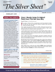
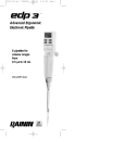
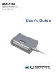
SlideStation-10 Model AC028 & AC028-EU Operating Instructions N2400337 Rev. 1 Table of Contents 1.0 2.0 3.0 4.0 5.0 6.0 7.0 8.0 9.0 10.0 11.0 Safety ………………………………………………………………3 Product Information …………………………………………….4 Assembly …………………………………………………………..4 3.1 Unpacking Unit ……………………………………………4 Identification of Controls ……………………………………….5 Installation ………………………………………………………...5 Operation …………………………………………………………5 6.1 Normal Operation ………………………………………..6 6.2 Program Mode ……………………………………………7 Technical Specifications ……………………………………….8 Maintenance and Service …………………………………….8 8.1 Contrast Adjustment ……………………………………..8 8.2 Calibration …………………………………………….. 8, 9 8.3 Cleaning …………………………………………………...9 8.4 Fuse Replacement ……………………………………...10 Fault Diagnostics ……………………………………………….10 Warranty …………………………………………………………11 Service ……………………………………………………………11 N2400337 Rev. 1 PN2229A 1 Figure 1 Top of Unit 1. LCD Display 2. Power Key 3. Program Key 4. Set Key 5. Stop/Start Key 6. Up/Down Keys Figure 2 Front of Unit Figure 3 Rear of Unit 7. AC Power Socket N2400337 Rev. 1 PN2229A 2 1.0 Safety The following symbols marked on the equipment mean: Caution: Read these operating instructions fully before use and pay particular attention to sections containing this symbol. Attention: Suivre attentivement les instructions avant l’usage et prêtez une attention particulière aux sections comportant ce symbole. Caution: Surfaces can become hot during use. Attention: Les surfaces peuvent devenir brûlantes pendant l’usage. Always observe the following safety precautions: Use only as specified by the operating instructions or the intrinsic protection may be impaired. After transport or storage in humid conditions, dry out the unit before connecting it to the supply voltage. During drying out the intrinsic protection may be impaired. Connect only to a power supply that provides a safety ground terminal. Do not block the ventilation openings. Do not touch surfaces that become hot during high temperature operation. Do not operate this unit unattended. Do not use this product in the presence of flammable or combustible materials. Ensure that the operating temperature is less than the maximum operating temperature of your sample material. Ensure that the power switch is easily accessible during use. Do not block or restrict ventilation slots. If liquid is spilled inside the unit, disconnect it from the power supply and have it checked by a competent person. It is the user’s responsibility to carry out the appropriate decontamination if hazardous material is spilled on or inside the equipment. It is the user’s responsibility not to use decontamination or cleaning agents the could cause a hazard due to reaction with the equipment or material contained in it. Consult the manufacturer or distribution agent if there is any doubt about the compatibility of decontamination or cleaning agents with the equipment or material contained in it. N2400337 Rev. 1 PN2229A 3 2.0 Product Information The AdvanDx SlideStation-10 is designed to provide a heating platform and chamber capable of maintaining either dry or highly humid conditions for PNA FISH, QuickFISH and other in-situ hybridization applications. The AdvanDx SlideStation-10 can hold up to 10 standard microscope slides and can be programmed so the user can define up to 3 ramp/timer segments. The digital microprocessor control offers full programmability of up to three time controlled temperature set points. The precise temperature control, sealed chamber, and high density heating plate offer the ideal environment for controlled hybridization reactions. The unit also provides two humidity generation wells which can be used to create a humid environment for 12 or more hours. The unit comes with a hinged see-through tempered glass lid for observing reactions and verifying humidity conditions. There is sufficient clearance (13/32”/1cm) between the heat plate and the bottom of the glass lid to allow for the use of most in-situ cell carriers and for adding a flat surface temperature gauge to verify slide temperature. 3.0 Assembly 3.1 Unpacking the Unit Remove the packing materials carefully, and retain for future shipment or storage of the unit. Inspect for damage. Report all shipping damage to the carrier immediately. Shipping damage is covered by the carrier and repair/replacement for shipping damages must be coordinated through the carrier. Package should contain: Programmable Slide Station Power Line Cord Operating Instructions Calibrated thermometer N2400337 Rev. 1 PN2229A 4 4.0 Identification of Controls 4.1 Identification of Controls (See Figures 1, 2 and 3 on Page 2) 1. 2. 3. 4. 5. 6. 7. 5.0 LCD Display – Displays current data and actual settings Power Key – Controls power to the unit Program Key – Used to toggle between Programs 1-3 Set Key – Used to set Temperature and Time settings Stop/Start – Used to start, pause and reset programs (▲)(▼) - Used to adjust temperature and time settings AC Power Socket Installation 5.1 Place the unit on a flat and stable surface. The unit is equipped with leveling feet which can be used to level the unit on the work surface. Ensure the unit has at least 6” clearance above, to allow for sufficient clearance of the hinged lid when fully open. 5.2 Fit the power line cord supplied with the unit into the power socket on the rear of the unit and plug the power cord into a properly grounded outlet. 5.3 Although the unit heats rapidly, pre-heat the unit to the desired operating temperature before incubating samples. If a humid chamber is desired, fill both of the humidity wells with about 1/8” of distilled water. 5.4 To load the unit with slide samples, open the lid to desired height. Place up to 10 slides onto the heat plate between the two humidity wells allowing a minimum of 1/16” clearance between each slide. Close the lid . 5.5 To remove slides, open the lid and remove slides, while observing caution below. Caution! The lid and heating plate may be hot. Make sure to use caution when removing slides. 6.0 Operation This unit can be operated in normal mode, or a programmable mode where the user can define and control up to 3 ramp/timed segments. Both of these modes will be described below. N2400337 Rev. 1 PN2229A 5 6.1 Normal Operating Mode 6.1.1 For a non-timed operation, depress the “program” button until P1 (program 1) is displayed. To set the unit to the desired temperature, depress the “Set” button until the “Set” colon on the top line of the display is flashing. 6.1.2 Using the up down arrow keys, select the desired temperature. The unit will begin to heat up to desired temperature. When the unit is calling for full heater power a white square will illuminate in the lower right corner of the display. When the unit is beginning to equilibrate the white square will begin to flash. When the unit is not calling for any heat the white square will disappear. 6.1.3 For a timed operation, verify “P2” (Program 2) and “P3” (Program 3) are “off” by depressing the Program Key until “P2” is displayed. Use the Down Arrow Key to reduce the temperature set point until the set display reads “off”. The lowest settable temperature is 18°C, “off” is the next setting below 18°C. Depress the Program Key until display reads P3 and set P3 to “off.” 6.1.4 Depress the “Program” Key to return the unit to P1. 6.1.5 Depress the “Set” Key until the “Time” colon is flashing. Use the “Up/Down” Keys to select the desired time setting. The Time display reads min:sec and there is a speed up algorithm to reach the desired time value quickly. 6.1.6 Depress the “Start” Key to start the timed operation. The display will begin to count down, when 00:00 is reached, the alarm will beep 3 times and the display will alternate between “Cycle Complete” and the main information screen. The timer can be paused at any time by pressing the Start/Stop Key. Note: The heater does not shut off at the conclusion of a timed operation. 6.1.6 Press and hold the Start/Stop Key for 3 seconds to reset the timer back to the last timed setting. N2400337 Rev. 1 PN2229A 6 6.2 Program Mode The unit can be programmed to run up to 3 consecutive temp/timer operations. These are referred to on the display as P1, P2, and P3. 6.2.1 Press the Program Key until P1 is displayed, to set the P1 temperature, depress the “Set” button until the Set colon on the display is flashing. Use the Up/Down arrow keys to select desired set temperature. 6.2.2 To set the P1 time, depress the “Set” Key until the Time colon on the display is flashing. Use the Up/Down arrow Keys to select desired time setting. Time display reads min:sec. 6.2.3 To set P2 temperature and time setting, follow steps 6.2.1 and 6.2.2 and select P2 rather than P1. 6.2.4 If you are running the program with only P1 and P2 and not using P3 turn P3 off by using the program button to select P3, use the Down arrow key to reduce the temperature set point until the display reads “Off” which is one setting below 18°C. 6.2.5 To set P3 temperature and time setting, follow steps 6.2.1 and 6.2.2 and select P3. 6.2.6 Press the “Start/Stop” Key to start the program. Note: The heater does not shut off at the conclusion of a timed operation. 6.2.8 Press and hold the Start/Stop button for 3 seconds to reset the timer back to the last timed setting. N2400337 Rev. 1 PN2229A 7 7.0 Technical Specifications This equipment is for indoor use, with maximum relative humidity of 80% non-condensing. Installation category II (transient voltages). Pollution degree 2 in accordance with IEC 664. For operation at altitudes of up to 6500 feet. Ambient Temperature Operating Range Temperature Setting Range Stability Uniformity Temperature Display Resolution Supply Ratings Power Rating Heating Rate Net Weight Exterior Dimensions (w x h x d) 18.0°C to 30.0°C Ambient +5°C to 100°C ±0.2°C throughout operating temperatures ±0.35°C at 37°C; ±0.7°C at 65°C 0.1°C Model 280001: 115 VAC, +/- 10%, 0.99A, 60 Hz Model 280001-2: 230 VAC, +/- 10% 0.50 A, 50/60 Hz Model 280001: 114 W Model 280001-2: 114 W Ambient to 65°C in 20 minutes 12 lb 16.0” x 3.75” x 9.75” This product has been tested to the requirements of CAN/CSA-C22.2 No. 61010-1, second edition, including Amendment 1, or a later version of the same standard incorporating the same level of testing requirements. 8.0 Maintenance and Service 8.1 Contrast Adjustment 8.1.1 With the unit powered up, hold the “Program” Key and the “UP” button to increase LCD contrast. 8.1.2 With the unit powered up, hold the “Program” Key and the “down” button to decrease LCD contrast. 8.2 Calibration 8.2.1 Monitor the center of the heating block with a calibrated temperature measuring device. The sensor should be backed with a piece of foam thick enough, so that when the glass lid is closed there is ample pressure to stabilize and insulate the sensor. N2400337 Rev. 1 PN2229A 8 8.2.2 With the unit powered on, set the P1 temperature setpoint to 18°C. Turn unit off by pressing the “Power” Key. 8.2.3 To enter the calibration mode, simultaneously hold down the “Up and Down” arrow keys while depressing the “Power” Key. 8.2.4 Verify the unit is not calling for any heat, which is indicated by observing that the white block in the lower right corner of display is not illuminated or flashing. If the unit is calling for heat, the ambient temperature is too cool to perform calibration. 8.2.5 After the actual temperature has stabilized, adjust the zero calibration so that the display agrees with the calibrated temperature measuring device. 8.2.6 Power the unit down by pressing the “Power” Key. Power the unit back up by pressing the “Power” Key. 8.2.7 Adjust the P1 temperature setpoint to 80°C. Power the unit back down by pressing the “Power” Key. 8.2.8 Enter the calibration mode as per step 8.2.3. Allow the unit to heat up and stabilize to 80.0°C. 8.2.9 Press the “Program” Key to select the span adjustment. 8.2.10 Adjust the span calibration so that the actual display temperature agrees with the calibrated temperature measuring device. 8.2.11 Power the unit down by the pressing the “Power” Key. Calibration is now complete. 8.3 Cleaning 8.3.1 Disconnect the power cord prior to cleaning and let the unit cool down. 8.3.2 If a spill occurs, use appropriate clean-up procedures as required for radiation or biohazard control. 8.3.3 Use a cloth dampened with warm water to clean the outer housing and heat block. Use general glass cleaner to clean the glass cover. N2400337 Rev. 1 PN2229A 9 8.4 Fuse Replacement 9.0 8.4.1 To replace the fuse, remove the power cord from back of unit. Open the fuse cover which is located above the power cord receptacle on the back of the unit. 8.4.2 Replace fuse with a 1.6A, 250V, Type F for 115v unit and 0.8A 250V, Type F for 230v unit. Reinstall the cover. Fault Diagnosis Symptom Unit does not operate Possible Cause a. Unit not powered on b. Unit not plugged into power supply c. Fuses blown d. Power supply failure Chamber temperature does not rise when expected Temperature continues to rise when not expected a. Actual temperature is higher than set temperature b. Temperature control circuit fault a. Actual temperature is lower than set temperature b. Temperature control circuit fault Action Required a. Press the Power Key b. Plug in, Power on c. Replace fuses (see section 8.4) d. Check that other electrical appliances on the same circuit are working a. Check set temperature b. Have unit checked by a competent service person a. Check set temperature b. Have unit checked by a competent service person Temperature Display stabilizes, but differs from independent calibrated temperature probe a. Unit is in need of calibration a. Refer to section 8.2, temperature calibration LCD Display is too dim or too bright a. Display needs contrast adjustment a. Refer to section 8.1, Contrast Adjustment N2400337 Rev. 1 PN2229A 10 10.0 Warranty When used in laboratory conditions and according to these operating instructions, AdvanDx warrants this product to be free of defective material and workmanship for a period of two years from the date of manufacture. The liability of AdvanDx for any defective equipment during the warranty period shall be limited to the repair of such equipment or replacement thereof without charge for parts or labor. 11.0 Service It is required to obtain a Returned Material Authorization (RMA) number before any AdvanDx products are returned for any reason. A Decontamination Certificate must be completed, signed by the user, and returned to AdvanDx prior to receiving the RMA number. Please be sure to mark the outside of the returned goods package with this RMA number, in order to ensure prompt handling. AdvanDx 400 TradeCenter, Suite 6990 Woburn, MA 01801 Phone: 866-376-0009 Fax: 781-376-0111 e-mail: [email protected] N2400337 Rev. 1 PN2229A 11