1
SERVICE MANUAL
YM6000 Patient Monitor
EU representative TECNOMED 2000 S.L. Valencia, 25 ‐ 28012 Madrid Spain Manufacturer Mediana Co., Ltd. Wonju Medical Industry Park, 1650‐1 Donghwa‐ri, Munmak‐eup, Wonju‐si, Gangwon‐do, Korea Tel: (82) 2 542 3375 (82) 33 742 5400 Fax: (82) 2 542 7447 (82) 33 742‐5483 YM6000 Service Manual Revised Date: 0607 Part Number‐Revision: A7066‐1 Printed in Korea Copyright © 2006‐2007 Mediana Co., Ltd. All rights reserved. Notice This document contains proprietary information that is protected by copyright. All Rights Reserved. Reproduction, adaptation, or translation without prior written permission is prohibited, except as allowed under the copyright laws. Warranty The information contained in this document is subject to change without notice. Mediana makes no warranty of any kind with regard to this material, including, but not limited to, the implied warranties or merchantability and fitness for a particular purpose. Mediana shall not be liable for errors contained herein or for incidental or consequential damages in connection with the furnishing, performance, or use of this material. Revision History The documentation part number and revision number indicate its current edition. The revision number changes when a new edition is printed in accordance with the revision history of the documentation. Minor corrections and updates which are incorporated at reprint do not cause the revision number to change. The document part number changes when extensive technical changes are incorporated. Contents
Introduction ............................................................................................................................................................ 1
Warnings ......................................................................................................................................................... 1
Cautions .......................................................................................................................................................... 2
Manual Overview .......................................................................................................................................... 3
Related Documents........................................................................................................................................ 3
Intended Use for the YM6000 Monitor ....................................................................................................... 3
Identifying the YM6000 monitor Configurations ...................................................................................... 3
Monitor Controls............................................................................................................................................ 4
Routine Maintenance............................................................................................................................................ 9
Cleaning .......................................................................................................................................................... 9
Periodic Safety and Functional Checks....................................................................................................... 9
Batteries ......................................................................................................................................................... 10
Environmental Protection........................................................................................................................... 10
Performance Verification.................................................................................................................................... 11
General .......................................................................................................................................................... 11
Required Equipment ................................................................................................................................... 11
System Tests.................................................................................................................................................. 12
Performance Tests ........................................................................................................................................ 15
Safety Tests.................................................................................................................................................... 31
Service Menu and Factory Default Settings ................................................................................................... 35
General .......................................................................................................................................................... 35
Service Menu ................................................................................................................................................ 35
Demo Mode .................................................................................................................................................. 40
EtCO2 Calibration......................................................................................................................................... 40
Factory Default Settings .............................................................................................................................. 40
Firmware Download ........................................................................................................................................... 45
Troubleshooting................................................................................................................................................... 47
General .......................................................................................................................................................... 47
How to Use This Section ............................................................................................................................. 47
Who Should Perform Repairs..................................................................................................................... 47
Replacement Level Supported ................................................................................................................... 47
Troubleshooting Guide ............................................................................................................................... 48
Disassembly Guide ............................................................................................................................................. 61
General .......................................................................................................................................................... 61
Replacement Level Supported ................................................................................................................... 63
Prior to Disassembly.................................................................................................................................... 63
Fuse Replacement ........................................................................................................................................ 63
Battery Replacement.................................................................................................................................... 63
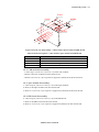
Monitor Disassembly................................................................................................................................... 64
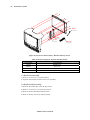
Front Case Disassembly (C)........................................................................................................................ 66
Rear Case Disassembly (D)......................................................................................................................... 72
Spare Parts............................................................................................................................................................. 77
General .......................................................................................................................................................... 77
Obtaining Replacement Parts ..................................................................................................................... 77
Packing for Shipment ......................................................................................................................................... 81
General Instructions .................................................................................................................................... 81
Returning the YM6000 monitor ................................................................................................................. 81
Repacking In Original Carton .................................................................................................................... 81
Repacking In a Different Carton ................................................................................................................ 82
System Processing Description ......................................................................................................................... 83
YM6000 Service Manual
ii Contents
System Overview ......................................................................................................................................... 83
System Block Diagram ................................................................................................................................ 83
ECG Processing ............................................................................................................................................ 89
NIBP Processing ........................................................................................................................................... 89
SpO2 Processing............................................................................................................................................ 91
Respiration Processing ................................................................................................................................ 93
Temperature Processing.............................................................................................................................. 93
Invasive Blood Pressure Processing .......................................................................................................... 94
Figures Figure 1. Front Panel Controls and Connectors ........................................................................................................................4 Figure 2. Rear Panel Components and Symbols........................................................................................................................5 Figure 3. Right Panel Components and Symbols ......................................................................................................................6 Figure 4. Left Panel Components and Symbols .........................................................................................................................7 Figure 5. Alarm Audible Test ..................................................................................................................................................12 Figure 6. Tone Audible Test .....................................................................................................................................................13 Figure 7. Backup RAM Clear ..................................................................................................................................................14 Figure 8. Pressure Sensor Accuracy Test.................................................................................................................................24 Figure 9. Air Leakage Test .......................................................................................................................................................25 Figure 10. The access of Service Menu via Set‐up menu.........................................................................................................35 Figure 11. The access of Service Menu via Set‐up menu .........................................................................................................36 Figure 12. Service Menu .........................................................................................................................................................36 Figure 13. Firmware downloading display ..............................................................................................................................45 Figure 14. Firmware downloading display ..............................................................................................................................46 Figure 15. Disassembly Sequence Flow Chart.........................................................................................................................62 Figure 16. Battery and Handle Disassembly ...........................................................................................................................64 Figure 17. Monitor Disassembly .............................................................................................................................................65 Figure 18. Front Case Disassembly – Side connector holder and Main board.........................................................................66 Figure 19. Front case disassembly – CPU module, SpO2 module and IBP board....................................................................67 Figure 20. Front Case Disassembly –Bracket and Key board ..................................................................................................68 Figure 21. Front Case Disassembly – sLCD and Bracket ........................................................................................................69 Figure 22. Front Case Disassembly – Knob, LCD window, Encoder assembly and Connectors .............................................70 Figure 23. Rear case disassembly – EtCO2 module..................................................................................................................72 Figure 24. Rear case disassembly – Speaker.............................................................................................................................73 Figure 25. Rear case disassembly –SMPS case, SMPS and NIBP module..............................................................................74 Figure 26. Rear case disassembly – Printer module and AC inlet ...........................................................................................75 Figure 27. YM6000 Exploded View – Spare Parts ..................................................................................................................78 Figure 28. System Block Diagram ...........................................................................................................................................83 Figure 29. Power Unit Block Diagram ....................................................................................................................................84 Figure 30. Process Unit Block Diagram ..................................................................................................................................84 Figure 31. User‐Control Unit Block Diagram.........................................................................................................................84 Figure 32. Sound Unit Block Diagram....................................................................................................................................85 Figure 33. Communication Unit Block Diagram ....................................................................................................................85 Figure 34. GUI Unit Block Diagram.......................................................................................................................................85 Figure 35. Thermal Printer Unit Block Diagram ....................................................................................................................85 Figure 36. NIBP Unit Block Diagram.....................................................................................................................................86 Figure 37. EtCO2 Unit Block Diagram ...................................................................................................................................86 Figure 38. ECG Unit Block Diagram ......................................................................................................................................86 Figure 39. Respiration Unit Block Diagram............................................................................................................................87 Figure 40. SpO2 Unit Block Diagram......................................................................................................................................87 Figure 41. Temperature Unit Block Diagram ..........................................................................................................................87 Figure 42. IBP Unit Block Diagram ........................................................................................................................................88 Figure 43. Analog Control Unit Block Diagram .....................................................................................................................88 Figure 44. Oxyhemoglobin Dissociation Curve.......................................................................................................................92 Tables Table 1. Required Equipment................................................................................................................................................... 11 Table 2. Parameter Alarm Limit Factory Defaults...................................................................................................................18 Table 3. Earth Leakage Current Values ....................................................................................................................................31 Table 4. Enclosure Leakage Current.........................................................................................................................................32 Table 5. Patient Leakage Current Values .................................................................................................................................33 Table 6. Patient Leakage Current Values ‐ Mains Voltage on Applied Part.............................................................................33 Table 7. Test Lead Combinations..............................................................................................................................................34 Table 8. Allowable Leakage Current.........................................................................................................................................34 Table 9. Service Menu..............................................................................................................................................................37 YM6000 Service Manual
Contents iii
Table 10. Audible Alarm Characteristics .................................................................................................................................38 Table 11. System Test ...............................................................................................................................................................39 Table 12. NIBP Test .................................................................................................................................................................40 Table 13. Factory Default Settings ..........................................................................................................................................40 Table 14. Required Equipments for Firmware download .........................................................................................................45 Table 15. Completion codes ......................................................................................................................................................46 Table 16. Firmware Downloading Error Codes .......................................................................................................................54 Table 17. Alarm Messages and Check Items ............................................................................................................................54 Table 18. Part Descriptions – Battery and Handle ..................................................................................................................64 Table 19. Part Descriptions – Monitor ....................................................................................................................................65 Table 20. Part Descriptions – Side connector holder and Main board .....................................................................................66 Table 21. Part Descriptions – CPU module, SpO2 module and IBP board ..............................................................................67 Table 22. Part Descriptions –Bracket and Key board...............................................................................................................68 Table 23. Part Descriptions – LCD and Bracket......................................................................................................................69 Table 24. Part Descriptions – Knob, LCD window, Encoder assembly and Connectors..........................................................70 Table 25. Part Descriptions – EtCO2 module ..........................................................................................................................72 Table 26. Part Descriptions – Speaker .....................................................................................................................................73 Table 27. Part Descriptions –SMPS case, SMPS and NIBP module ......................................................................................74 Table 28. Part Descriptions – Printer module and AC inlet....................................................................................................75 Table 29. Parts List ..................................................................................................................................................................79 YM6000 Service Manual
iv Contents
This page is intentionally left blank. YM6000 Service Manual
Introduction
Warnings Warnings are identified by the WARNING symbol shown above. Warnings alert you to potential serious outcomes (death, injury, or adverse events) to the patient or user. WARNING: Explosion hazard. Do not use the monitor in the presence of flammable anesthetics or gases. WARNING: Do not spray, pour, or spill any liquid on the monitor, its accessories, connectors, switches, or openings in the chassis. WARNING: Do not immerse the monitor or its accessories in liquid or clean with caustic or abrasive cleaners. WARNING: Ensure that conductive portions of the electrodes, leads, and cable do not come into contact with any other conductive parts, WARNING: Before attempting to open or disassemble the monitor, disconnect the power cord from the monitor. WARNING: Chemicals from a broken LCD display panel are toxic when ingested. Use caution when handling a monitor with a broken display panel. WARNING: The use of accessories, transducers, and cables other than those specified may result in increased emission and/or decreased immunity of the monitor. WARNING: Do not silence the monitor audible alarm or decrease its volume if patient safety could be compromised. WARNING: During the safety test, AC main voltage will be present on the applied part terminals, Exercise caution to avoid electrical shock hazard. WARNING: Do not place the monitor into operation after repair or maintenance has been performed, until all Performance Tests and Safety Tests listed in Performance Verification section of this service manual have been performed. Failure to perform all tests could result in erroneous monitor readings. WARNING: High voltage is generated by the LCD backlight driver. Exercise caution when operating monitor with covers open. YM6000 Service Manual
2 Introduction
Cautions Cautions are identified by the CAUTION symbol shown above. Caution statements identify conditions or practices that could result in damage to the equipment or other property. CAUTION: Observe ESD (electrostatic discharge) precautions when working within the unit and/or when disassembling and reassembling the monitor and when handling any of the components of the monitor. CAUTION: When reassembling the monitor, over‐tightening could strip out the screw holes in the cases, rendering it unusable. CAUTION: If any problem with the monitor built in an optional printer, check a printer’s door is closed well. Operating error may be caused if the cover is not closed correctly. CAUTION: If internal battery cable has been disconnected, pay particular attention to polarity of the cable before reattaching. If battery cable polarity is reversed, it is likely that circuit damage will occur. CAUTION: For continued protection against risk of fire, replace only with same type and rating of fuse. CAUTION: Ferrite Cores are used for electromagnetic compatibility. Please do not remove Ferrite Cores while disassembling or reassembling, otherwise the monitor can be affected by electromagnetic interference and measure inaccurate data to be displayed or stored. YM6000 Service Manual
Introduction 3
Manual Overview This manual contains information for servicing the YM6000 monitor. The monitor subsequently referred to as the monitor throughout this manual. Only qualified service personnel should service this product. Before servicing the monitor, read the operator’s manual carefully for a thorough understanding of safe operation. Read and understand all safety warnings and service notes printed in this service manual. and the operator’s manual part number A7076. Related Documents To perform test and troubleshooting procedures and to understand the principles of operation and circuit analysis sections of this manual, you must know how to operate the monitor. Refer to the monitor operator’s manual part number A7076. To understand the various SpO2 sensors, ECG leads, blood pressure cuffs, and temperature probes that work with the monitor, refer to the individual directions for use that accompany these accessories. Intended Use for the YM6000 Monitor The YM6000 monitor is intended to be used to monitor electrocardiography, heart rate, pulse rate, noninvasive blood pressure (systolic, diastolic and mean arterial pressures), functional arterial oxygen saturation, invasive blood pressure, respiration, capnography (EtCO2 and InCO2) and temperature for adult, pediatric and neonate patients in all areas of a hospital and hospital‐type facilities. Monitor users should be skilled at the level of a technician, doctor, nurse or medical specialist. Note: Hospital use typically includes such areas as general care floors, operating rooms, special procedure areas, intensive and critical care area, within the hospital. Hospital‐type facilities include physician office‐based facilities, sleep labs, skilled nursing facilities, surgicenters, and sub‐acutecenters. Identifying the YM6000 monitor Configurations The following table identifies YM6000 monitor configurations and how they are indicated. The model‐option number and serial number are located on the back of the monitor. All information in this manual, including the illustrations, is based on a monitor configured with the Capnography (EtCO2 and InCO2), IBP and recorder. If the relevant functions do not exist, please verify your unit configuration. Model‐option Description
YM6000‐0 Basic (ECG, NIBP, SpO2, 2‐channel Temperature, Respiration) YM6000‐P0 Basic + Recorder YM6000‐0B Basic + IBP YM6000‐0E Basic + Capnography YM6000‐P0B Basic + Recorder +IBP YM6000‐P0E Basic + Recorder + Capnography YM6000‐0BE Basic +IBP + Capnography YM6000‐P0BE Basic + Recorder + IBP + Capnography YM6000 Service Manual
4 Introduction
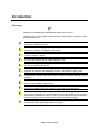
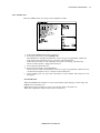
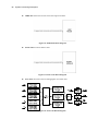
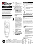
Monitor Controls Front Panel Controls and Connectors 1 2 3 4 5 6 7 8 9 10
11
12
13
14
15
16
17
18
19
20
21
Visual alarm indicator LCD (Liquid crystal display) Power on indicator Battery charging status indicator A Battery charging status indicator B AC indicator Power button Print button Alarm silence/suspension button Trend button NIBP start/stop button Return button Trim knob ECG connector SpO2 connector NIBP connector Temperature channel 1 Temperature channel 2 CO2 connector (option) IBP 1 connector (option) IBP 2 connector (option) Figure 1. Front Panel Controls and Connectors YM6000 Service Manual
Introduction 5
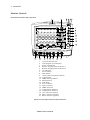
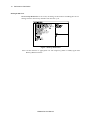
Rear Panel Components 1 2 3 4 Air ventilation Equipotential terminal Ac power connector Speaker 5
6
7
Battery cover Thermal Printer (option)
Handle Figure 2. Rear Panel Components and Symbols YM6000 Service Manual
6 Introduction
Right Panel Components 1 LAN connector 2 RS‐232 interface connector
Figure 3. Right Panel Components and Symbols YM6000 Service Manual
Introduction 7
Left Panel Components 1 Thermal printer (option)
2 Battery cover
Figure 4. Left Panel Components and Symbols YM6000 Service Manual
8 Introduction
This page is intentionally left blank. YM6000 Service Manual
Routine Maintenance
WARNING: Do not spray or pour any liquid on the monitor or its accessories. Do not immerse the monitor or its accessories in liquid or clean with caustic or abrasive cleaners. Cleaning The monitor may be surface‐cleaned by using a soft cloth dampened with either a commercial, nonabrasive cleaner or one of the solution listed in the below. Lightly wipe the top, bottom and front surfaces of the monitor lightly. z Quatemary Ammonium z Alcohol‐70% Isopropyl z 10% Chlorine bleach solution z PDI Sani‐System For cables, sensors, cuffs, and probes, follow cleaning instructions in the directions for use shipped with those components. Avoid spilling liquid on the monitor, especially in connector areas. If liquid is accidentally spilled on the monitor, clean and dry thoroughly before reuse. If in doubt about monitor safety, refer the unit to qualified service personnel for checking. Periodic Safety and Functional Checks The monitor requires no routine service or calibration other than cleaning and battery maintenance. The following performance verification tests may be used following repair or during routine maintenance (if required by your local institution). The following checks should be performed at least every 2 years by qualified service personnel. 1. Inspect the exterior of the monitor for damage. 2. Inspect labels for legibility. If the labels are not legible, contact Mediana Technical Service Department. 3. If the monitor has been visibly damaged or subjected to mechanical shock (for example, if dropped), perform the performance tests as described in Performance Verification section. If the unit fails these performance tets, refer to Troublehooting section. 4. Perform the electrical safety tests detailed in Performance Verification section. If the unit fails these electrical safety tests, do not attempt to repair. Contact Mediana Technical Service Department. 5. Inspect the fuses for proper value and rating. qty 2, 6.3 A, 250 volts for AC mains YM6000 Service Manual
10 Routine Maintenance
Batteries If the monitor has not been used for a long period of time, more than 2 months, the battery will need charging. To charge the battery, connect the monitor to an AC outlet as described in Battery Charge paragraph in this service manual or the Battery Operation section of the operator’s manual. Note: Storing the monitor for a long period without charging the battery may degrade the battery capacity. The battery may require a full charge/discharge cycle to restore normal capacity. Mediana recommends that the monitor’s sealed, Ni‐
MH batteries be replaced at 2 year intervals. Refer to Disassembly Guide section. CAUTION: If the monitor is to be stored for a period of 2 months or longer, it is recommended to notify service personnel to remove the battery from the monitor prior to storage. To replace or remove the battery, refer to Disassembly Guide section. Recharging the battery is strongly recommended when the battery has not been recharged for 2 or more months. CAUTION: If the battery shows any signs of damage, leakage, or cracking, it must be replaced immediately. CAUTION: Discarded battery may explode during incineration. Recycle used batteries properly. Do not dispose of batteries in refuse containers. Environmental Protection Follow local governing ordinances and recycling plans regarding disposal or recycling batteries and other device components. Note: The monitor should be disposed of separately from the municipal waste stream via designated collection facilities appointed by the government or the local authorities. Note: The correct disposal of your old appliance will help prevent potential negative consequences for the environment and human health. Note: For more detailed information about disposal of your old appliance, please contact your city office, waste disposal service or the shop where you purchased the monitor. YM6000 Service Manual
Performance Verification
General This section discusses the tests used to verify performance following repairs or during routine maintenance. All tests can be performed without removing the monitor covers. All tests except the battery charge and battery discharge tests must be performed as the last operation before the monitor is returned to the user. If the monitor fails to perform as specified in any test, repairs must be made to correct the problem before the monitor is returned to the user. Required Equipment Table 1 lists the equipment required for performance verifications. Table 1. Required Equipment Equipment Description Digital multimeter (DMM) Fluke Model 87 or equivalent ECG cable for 3 leads Mediana ECG cable for 3 lead ECG cable for 5 leads (option) Mediana ECG cable for 5 lead ECG leads Mediana ECG 3 lead ECG leads (option) Mediana ECG 5 lead NIBP hose Mediana cuff hose NIBP cuff Mediana cuff, Durable NIBP rigid PVC vessel 9cm diameter SpO2 extension cable Nellcor DOC‐10 SpO2 sensor (durable) Nellcor DS‐100A Temperature probes YSI‐400 series SpO2 simulator Nellcor SRC‐MAX simulator ECG simulator METRON PS‐420 or equivalent NIBP simulator Bio‐Tek BP Pump 2 or equivalent Respiration simulator METRON PS‐420 or equivalent Temperature simulator Medsim 300 or equivalent IBP simulator METRON PS‐420 or equivalent IBP test cable Mediana IBP test cable Calibration gas cylinder 8‐12% CO2, ±0.02% balance air or nitrogen Gas valve and non‐silicon tubing Gas valve and non‐silicon tubing Sample elbow or tee Sample elbow or tee CO2 gas flow meter BCI catalogue No. 8133 recommended Sample line Sample line Water trap Water trap CO2 scrubber CO2 scrubber (or 0% CO2 medical‐grade gas source) (or 0% CO2 medical‐grade gas source) Safety analyzer METRON QA‐90 or equivalent Data interface cable 9‐pin RS‐232 cable PC Common PC LAN cable Common used LAN cable Stopwatch Manual or electronic Note: Contact Mediana Technical Service Department for pricing and ordering information.
YM6000 Service Manual
12 Performance Verification
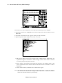
System Tests The monitor must be placed in the service menu. For a detailed explanation to access the service menu, refer to Service Menu and Factory Default Settings section. 1. Rotate the trim knob to select System Test in the service menu, and then press the trim knob. LCD Test This tests the LCD display. 1. Select LCD Test in the system test. 2. The screen color will change over the following sequence: Red Æ Green Æ Blue Æ White Æ Black … every two seconds 3. After testing the test, press trim knob twice to exit. Pass/Fail Results When the color of the test screen changes in the order from Red, Green, Blue, White to Black, the LCD display is in a normal state. Alarm Audible Test This tests the alarm tones by displaying the level of the alarm tone on the screen. 1.
2.
3.
Figure 5. Alarm Audible Test Select Alarm Audible Test in the system test. The level of the alarm tone will appear on the screen as the alarm tone sounds. Then, the level goes up gradually. When the tone reaches the maximum level 8, it returns to the minimum level 1. After finishing the test, press the trim knob to select Cancel. The menu box will disappear. Pass/Fail Results When the alarm tone changes to eight steps, the alarm tone is in a normal state. YM6000 Service Manual
Performance Verification 13
Tone Audible Test This tests HR/PR tones, key beeps and completion sounds. 1.
2.
3.
4.
5.
Figure 6. Tone Audible Test Select Tone Audible Test in the system test. Rotate the trim knob to select HR/PR Tone. The HR/PR tone sounds intermittently as the level goes up gradually. When the tone reaches the maximum level 7, it returns to the minimum 1. When the tone returns to the minimum, the pitch will change automatically. There are three pitches – High, Med and Low. Press Cancel to finish the test. Rotate the trim knob to select Key Beep. The key beep sounds intermittently as the level goes up gradually. When the tone reaches the maximum level 7, it returns to the minimum 1. After finishing the test, press the trim knob to select Cancel. The menu box will disappear. Pass/Fail Results When the HR/PR tone changes to seven steps and the pitch changes to three steps, the HR/PR tone is normally set. When the key beep changes to seven steps, the key beep is normally set. When the completion sound is heard, it is normally set. YM6000 Service Manual
14 Performance Verification
Backup RAM Clear When Backup RAM Clear is set to Yes, all settings of the monitor including the service settings return to the factory defaults from the next cycle. Figure 7. Backup RAM Clear Note: Set the monitor to appropriate AC line frequency (50Hz or 60Hz) again after Back Up RAM clearance. YM6000 Service Manual
Performance Verification 15
Performance Tests The battery charge and battery discharge test should be performed before monitor repairs whenever the battery is suspected as being a source of the problems. All other tests may be used following repairs or during routine maintenance (if required by your local institution). Before performing the battery discharge test, ensure that the battery is fully charged. This section is written using factory defaults set as power‐up. If your institution has preconfigured custom defaults, those values will be displayed. Power 1. Connect the monitor to AC power source using proper power cord. 2. Verify that AC indicator is lit. 3. Press Power button over 1 second to turn on the monitor. 4. Verify that the monitor is turned on and that Power on indicator is lit 5. After the monitor operates in normal mode, disconnect the power cord. 6. Verify that Battery status icon appears on the screen instead of lighting AC indicator. 7. Press Power button over 1 second, and then verify that the monitor is turned off. Battery Charge 1. Connect the monitor to AC power source using a proper power cord. 2. Verify AC indicator is lit. 3. Charge the battery fully until Battery charging status indicator A and B is no more flashing. It takes for at least 12 hours. 4. To check for a full charge, perform the procedure in paragraph “Battery Discharge”. Note: The battery may require a complete charge/discharge cycle to restore its normal capacity, depending on its previous usage. Battery Discharge 1. Disconnect the power cord from the monitor with fully charge battery. 2. Turn on the monitor by pressing Power button over 1 second. 3. Verify Battery status icon appears at bottom of the screen after power‐on self‐test is completed. The bar in battery status icon should be filled, indicating battery is charged. 4. Connect SpO2 simulator to monitor via the SpO2 extension cable. 5. Connect NIBP simulator to the monitor via Mediana hose. 6. Set SpO2 simulator as follows: SpO2 of 90% and pulse rate of 60bpm. 7. Set NIBP simulator to simulate pressure setting of 120/80 mmHg and heart rate of 80bpm. 8. Set NIBP Automatic mode interval of the monitor to 15 minutes. 9. The monitor must operate for 1 hour with one fully charged battery. The monitor must operate for at least 15 minutes before the monitor powers down due to low battery condition. 10. Verify that low priority audible alarm occurs and a warning message “low battery” is displayed about 15 minutes before battery fully discharges. YM6000 Service Manual
16 Performance Verification
11. Allow monitor to operate until it automatically powers down due to low battery condition. Verify that high priority audible alarm occurs and a warning message “Critically low battery” is displayed about 5 minutes before monitor automatically shuts down. 12. If monitor passes this test, immediately recharge battery. (paragraph “Battery Charge”) Power‐On Self‐Test 1. Connect the monitor to AC power source and verify that AC indicator is lit. 2. Observe the monitor’s front panel. With monitor off, press Power button. The monitor must perform the following sequence. a.
The monitor progresses the check sum for the flash memory and displays the bar while the check sum is proceeding b.
When the check sum completed, the bar is filled, and then Mediana logo appears for a few seconds, with version numbers of the software and the copyright in lower left corner of display. c.
The monitor emits the high‐pitched beep. d.
Visual alarm Indicator (red) on the top of the front panel, AC indicator (green) and battery charging status indicators A and B (green) on the right top of the front panel are illuminated. e.
Upon successful completion of power‐on self‐test, display will be in normal monitoring screen configuration. Note: Power‐on self‐test takes approximately 3 seconds to complete. No vital signs numeric values or waveforms will be displayed. Note: During the monitor’s power‐on‐self‐test, the integrity of all programming is checked first. If software testing is successful, hardware tests are initiated. If all testing is successful, the monitor is ready for use. If an error code is displayed, please refer to Troubleshooting section. YM6000 Service Manual
Performance Verification 17
General Operation Tests Alarms and Alarm Silence 1. Connect the monitor to an AC power source. 2. Press Power button to turn on the monitor. 3. Connect SpO2 simulator to sensor input cable and connect cable to monitor. 4. Set SpO2 simulator as follows: SpO2 of 75% and pulse rate of 60bpm. 5. Verify following the monitor reaction: a.
Pulse bar begins to track artificial pulse signal from SpO2 simulator. b.
After about 10 to 20 seconds, the monitor displays saturation and pulse rate as specified by simulator. Verify values are within following tolerances: z
z
c.
Tolerance of Oxygen Saturation : ±2 % Tolerance of Pulse Rate : ±3bpm Audible alarm sounds and “SpO2: Lower limit violated.” message will be displayed and % SpO2 numerical area will flash, indicating the parameter has violated default alarm limits. 6. Press Alarm silence/suspension button on the monitor front panel. Audible alarm is temporarily silenced. 7. Verify the following: a.
An audible alarm remains silenced. b.
Alarm silence icon appears in %SpO2 numerical area on display. c.
%SpO2 display continues flashing. d.
Audible alarm returns in approximately 120 seconds. HR/PR Tone Volume Control 1. Press Power button to turn on the monitor. 2. Connect SpO2 simulator to sensor input cable and connect cable to monitor. 3. Set SpO2 simulator as follows: SpO2 of 75% and pulse rate of 60bpm. 4. Verify SpO2 and pulse rate values are correctly displayed. 5. Press Alarm silence/suspension button on front panel of the monitor to temporarily silence audible alarm. 6. Verify HR/PR source on HR/PR numerical area is set to “SpO2”. 7. Select Setup icon on the screen to display Setup menu. 8. Rotate the trim knob to highlight HR/PR tone volume on Setup menu and press the trim knob to adjust HR/PR tone volume. 9. Set HR/PR tone volume level 1 to level 7 and return to the monitoring screen. Verify beeping pulse rate tone increases. 10. Set HR/PR tone volume level 7 to level 1 and return to the monitoring screen. Verify beeping pulse rate tone decreases. YM6000 Service Manual
18 Performance Verification
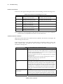
11. Set HR/PR tone volume to “Off” and return to the monitoring screen. Verify beeping pulse rate tone is no longer audible. 12. Return HR/PR tone volume to a comfortable level. Sensor LED Excitation Test This procedure uses normal system components to test circuit operation. A DS‐100A, used to examine LED intensity control. The red LED is used to verify intensity modulation caused by the LED intensity control circuit. 1. Connect the monitor to an AC power source. 2. Press the Power button to turn on the monitor. 3. Connect the SpO2 extension cable to the monitor. 4. Connect SpO2 sensor to the SpO2 extension cable. 5. Leave the sensor open with the LEDs and photo detector visible. 6. After monitor completes its normal power‐up sequence, verify that the sensor LED is brightly lit. 7. Slowly move sensor LED in proximity of photodetector element of the sensor (close the sensor slowly). Verify; as LED approaches the optical sensor, that the LED intensity decreases. 8. Open the sensor and notice that the LED intensity increases. 9. Repeat step 7 and intensity will again decrease. This variation is an indication that the microprocessor is in proper control of LED intensity. 10. Press Power button to turn off the monitor. Restoring Power‐On Default Settings The following test procedures will verify that alarms are activated at the level of factory default alarm limits and that any changed settings are saved and in effect when the user changes alarm limit settings and saves the current settings as a power default. Table 2. Parameter Alarm Limit Factory Defaults Factory Defaults Adult Pediatric Neonatal HR/PR High Alarm Limits 120 BPM 160 BPM 200 BPM HR/PR Low Alarm Limits 50 BPM 70 BPM 100 BPM NIBP SYS High Alarm Limits 160 mmHg 120 mmHg 90 mmHg NIBP SYS Low Alarm Limits s 90 mmHg 70 mmHg 40 mmHg NIBP DIA High Alarm Limits 90 mmHg 70 mmHg 60 mmHg NIBP DIA Low Alarm Limits 50 mmHg 40 mmHg 20 mmHg NIBP MAP High Alarm Limits 110 mmHg 90 mmHg 70 mmHg NIBP MAP Low Alarm Limits 60 mmHg 50 mmHg 30 mmHg % SpO2 High Alarm Limits 100 % 100 % 95 % % SpO2 Low Alarm Limits 90 % 90 % 80 % IBP1, 2 SYS High Alarm Limits 160 mmHg 120 mmHg 90 mmHg IBP1, 2 SYS Low Alarm Limits 90 mmHg 70 mmHg 40 mmHg IBP1, 2 DIA High Alarm Limits 90 mmHg 70 mmHg 60 mmHg IBP1, 2 DIA Low Alarm Limits 50 mmHg 40 mmHg 20 mmHg IBP1, 2 MEAN High Alarm Limits
110 mmHg 90 mmHg 70 mmHg IBP1, 2 MEAN Low Alarm Limits 60 mmHg 50 mmHg 30 mmHg RESP High Alarm Limits 30 BPM 30 BPM 100 BPM YM6000 Service Manual
Performance Verification 19
Factory Defaults RESP Low Alarm Limits EtCO2 High Alarm Limits EtCO2 Low Alarm Limits InCO2 High Alarm Limits InCO2 Low Alarm Limits TEMP1, 2 High Alarm Limits TEMP1, 2 Low Alarm Limits Adult 8 BPM 80 mmHg 0 mmHg 20 mmHg 0 mmHg 39.0°C (102.2°F)
36.0°C (96.8°F) Pediatric 8 BPM 80 mmHg 0 mmHg 20 mmHg 0 mmHg 39.0°C (102.2°F) 36.0°C (96.8°F) Neonatal 30 BPM 80 mmHg 0 mmHg 20 mmHg 0 mmHg 39.0°C (102.2°F)
36.0°C (96.8°F)
1. Turn on the monitor at the factory default settings. 2. Select Alarm limits icon to display Alarm limits menu. 3. Verify that alarm limits are set to as shown in Table 2. 4. Change Patient mode from Adult to Pediatric or Neonatal, then verify that alarm limits are set to as shown in Table 2. 5. Change alarm limit value via Alarm limits menu. 6. Save the current changed alarm limit values as a power on default setting via the service menu (see Service Menu and Factory Defaults section). Turn off the monitor. 7. Press Power button to turn on the monitor. 8. Verify alarm limits are set to the current changed alarm limit values. Printer Test (Option) If Printer option is installed in the monitor, the following test procedures will verify the printer performance. 1. Connect the monitor to an AC power source. 2. Press Power button to turn on the monitor. 3. Connect all necessary simulators to the monitor. 4. Select Setup icon on the screen to display Setup menu. 5. Test #1: 20 sec printing a.
Set Wave record time to 20 sec via Setup menu. b.
Press Print button when all the parameter signals display normally. c.
Verify that the parameter values and waveforms are printed out for 20 seconds. 6. Test #2: Continuous printing a.
Set Wave record time to Continuous via Setup menu. b.
Press Print button when all the parameter signals display normally. c.
Verify the parameter values and waveforms are printed out continuously. d.
Verify printing stops with pressing Print button again. YM6000 Service Manual
20 Performance Verification
7. Test #3: Record speed a.
Set Record speed to 25 mm/s. b.
Press Print button when all the parameter signals display normally. c.
Verify the parameter values and waveforms are printed out with 25 mm/s. d.
Set Record speed to 50 mm/s. e.
Press Print button when all the parameter signals display normally. f.
Verify that the parameter values and waveforms are printed out with 50 mm/s. 8. Test #4: Wave Record Select a.
Set Wave Record Select to ECG1+ECG2 via Setup menu. b.
Press Print Button when all the parameter signals display normally. c.
Verify the two ECG waveforms are printed out. d.
Repeat this test for other selections. 9. Test #5: Record on Alarm a.
Set Record on Alarm to On via Setup menu. b.
Set Heart rate of ECG simulator to 30 bpm. c.
Verify ”HR Lower limit violated” alarm is activated and the parameter values and waveforms are printed out. 10. Test #6: Auto List Record a.
Set Auto List Record to On via Setup menu. b.
Set Save Time Interval to 0.5 minutes via Tabular trend menu. c.
Verify that the monitor automatically prints out the data after stored 8 data in the trend memory. Note: If there is no printer paper left or printer paper places improperly, the monitor will display an informative message. Network Test Perform the following procedure to test the Network. The Network connector is located on the monitor’s right panel, identified with the Network symbol. CAUTION: Do not change any other settings of the test programs while performing the Network test. Note: Network Test is only available when YM6000 monitor is equipped with TCP/IP module for Central Monitoring System (CMS). Otherwise this test does not need to perform. Note: Contact Mediana Technical Service Department for the software required. 1. Connect the network line to the monitor, then turn on the monitor. 2. Run “YM6000_Comm_Test.exe” on PC connected the network line using the same gateway as the monitor. YM6000 Service Manual
Performance Verification 21
3. Press PROBE button on PC. 4. Verify that the number of the monitor connections to PC found is correct 5. Press EXIT button on PC to close “YM6000_Comm_Test.exe”. Nurse Call Test
Perform the following procedure to test the Nurse Call. The nurse call connector is Dsub‐9, located on the monitor’s right panel, identified with the data interface symbol (RS‐232). 1. Connect the negative lead of a voltmeter to pin 5 and positive lead to pin 1 of the data port connector on the right panel of the monitor. Ensure that the audible alarm is not silence or turned off. 2. Connect the SRC‐MAX simulator to the DOC‐10 sensor cable. 3. Connect temperature probe to temperature input port on YM6000. 4. Turn on the monitor and wait for the monitor to complete POST. Note: The monitor should indicate a %SpO2 alarm of 75. 5. Verify an output voltage at pins 5 and 1 between +5 to +12 DC. 6. Press Alarm silence/suspension button. With no active audible alarm, the output voltage at pins 5 and 1 must be between ‐5 to ‐12 VDC. This verifies the RS‐232 Nurse Call function. 7. With the instrument in an alarm condition, use a digital multmeter (DMM) to verify that there is no continuity (1 mega ohms or greater) between pins 8 and 9 and that there is continuity (60 ohms or less) between pins 7 and 8. 8. Press the SRC‐MAX simulator %SpO2 button to change the %SpO2 to 90. 9. Use a DMM to verify that there is continuity between pins 8 and 9 and that there is no continuity between pins 7 and 8. This verifies the solid state Nurse Call function. Note: The pin layouts and signal descriptions are included in the operator’s manual. For the detailed information regarding the Nurse Call, refer to Nurse Call Interface section of the operator’s manual. YM6000 Service Manual
22 Performance Verification
Measurement Parameter Operation Tests ECG Operation 1. Press Power button to turn on the monitor. 2. Connect 3 ECG leads to appropriate jacks on ECG simulator. 3. Connect leads to Mediana ECG cable. 4. Connect Mediana ECG cable to ECG connector on the monitor’s front panel. 5. Set ECG simulator as follows: z
z
z
z
z
Heart rate: 30 bpm Amplitude: 1 millivolt Lead select: II Normal sinus rhythm Adult mode 6. After normal power‐up sequence, verify that the following monitor reactions: a.
After about 15 seconds, the monitor displays a heart rate of 30 ±3 bpm. b.
Verify that audible alarm sounds and that “HR: Lower limit violated” message displays on the message area. c.
Verify that the HR/PR numerical area flashes and that the heart rate is below default low alarm limit (medium priority alarm). 7. Increase the heart rate setting on ECG simulator to 240 bpm. a.
After about 15 seconds, verify the monitor displays heart rate of 240 ±3 bpm. b.
Verify that audible alarm sounds and that “HR: Upper limit violated” message displays c.
Verify that the HR/PR numerical area flashes and that the heart rate is above default high alarm limit (medium priority alarm). 8. Decrease the heart rate setting on ECG simulator to 120 bpm. a.
After about 15 seconds, verify the monitor displays heart rate of 120 ±3 bpm. 9. Disconnect the LL lead from ECG simulator. a.
Verify that the “ECG: Check ECG leads & electrodes” message appears, that three dashes are displayed in the HR/PR numerical area, and that low priority audible alarm sounds. b.
Reconnect the LL lead to ECG simulator. Verify that “ECG: Check ECG leads & electrodes” message no longer appears and that the audible alarm is stopped. c.
Repeat this test for the LA and the RA leads. 10. Connect all the leads to the monitor. a.
Select ECG waveform menu and set Lead select to Lead I. b.
Verify that the lead selection is displayed on the ECG waveform area. c.
Repeat step 10‐a for all the ECG Lead selections. 11. Set ECG Lead selection to Lead II. 12. Change ECG waveform size to all the selectable sizes and verify that an appropriate size is displayed on the ECG waveform area. YM6000 Service Manual
Performance Verification 23
13. Set ECG Cable Select to Auto via ECG waveform menu. 14. Verify that Lead Select in ECG waveform menu displays I, II, III. 15. Disconnect 3 ECG leads and connect 5 ECG leads. 16. Verify that Lead Select in ECG waveform menu displays I, II, III, aVR, aVL, aVF, V (Chest Lead). 17. Repeat step 9 to 12. 18. Turn off the monitor. Note: The accuracy of the monitor ECG measurements is ±3 bpm. In the procedure, add the tolerance of the simulator to the acceptable range of readings. NIBP Operation WARNING: A blood pressure cuff, connected to the monitor, should never be applied to a human subject while the monitor is in the pressure test mode, as injury could result. These tests verify the functionality of the monitor’s pneumatic system. The monitor must be placed in Service menu. For a detailed explanation to access the service menu, refer to Service Menu and Factory Default Settings section. 1. Rotate the trim knob to select NIBP Test in the service menu, and then press the trim knob. Note: Before accessing the NIBP Test mode, ensure that current patient mode is proper for the pneumatic system to be test. You can set Patient mode: Adult, Pediatric or Neonatal via the setup menu. Note: In the NIBP Test mode, no function button will have no effect except the trim knob. All the tests will start to be performed by pressing or rotating the trim knob. If you would like to stop the test during test progressing, press the trim knob. Note: Inflation Speed Test and Deflation Speed Test are intended for factory use only. YM6000 Service Manual
24 Performance Verification
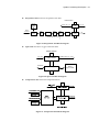
Pressure Sensor Accuracy Test 1.
Figure 8. Pressure Sensor Accuracy Test Connect the NIBP cuff hose to the NIBP connector on the monitor’s front panel. 2.
Connect the other end of the NIBP cuff hose to the NIBP simulator. 3.
Rotate the trim knob to select NIBP Test in the service menu, and then press the trim knob. 4.
Rotate the trim knob to select Pressure Sensor Accuracy Test, and then press the trim knob. 5.
Press Select button on the simulator until simulator displays “Pressure Source Set Test Pressure”. Adjust pressure on the simulator for 250, 150, 50 and 0 mmHg. 6.
Press Start Pump button on simulator. The simulator will begin to pressurize. Allow 15~20 seconds for pressure to stabilize. 7.
Compare the pressure of the simulator with the pressure displayed by the monitor. If air leakage disables accurate comparison of the above pressures, eliminate the cause of air leakage. 8.
After finishing the test, press the trim knob to select Cancel. The menu box will disappear. If Cancel is selected during the test progressing, the test will stop and the menu box will disappear. Pass/Fail Results The difference between the simulator’s and the monitor’s readings are as follows: Sphygmomanometer Monitor’s Readings 0 mmHg ±0 mmHg 50 mmHg 50±6 mmHg 100 mmHg 100±6 mmHg 200 mmHg 200±6 mmHg YM6000 Service Manual
Performance Verification 25
Air Leakage Test The air leakage test verifies the integrity of the pneumatic system. 1.
Figure 9. Air Leakage Test Place the adult cuff with a rigid PVC vessel (5 cm diameter). 2.
Connect the cuff to the NIBP connector on the monitor’s front panel via NIBP cuff hose. 3.
Rotate the trim knob to select NIBP Test in the service menu, and then press the trim knob. 4.
Rotate the trim knob to select Air Leakage Test, and then press the trim knob. 5.
The result will be displayed on the monitor’s screen in four minutes. 6.
After finishing the test, press the trim knob to select Cancel. The menu box will disappear. If Cancel is selected during the test progressing, the test will stop and the menu box will disappear. Pass/Fail Results It passes if the leakage value is less than 12mmHg/3minutes. YM6000 Service Manual
26 Performance Verification
Pulse Oximetry Operation 1. Connect the monitor to an AC power source. 2. Turn on the monitor by pressing the Power button. 3. Connect the SpO2 extension cable to SpO2 connector on the monitor’s front panel after the monitor completes POST. 4. Connect the SpO2 simulator to the other end of the SpO2 extension cable. 5. The monitor will: ‐ be in SpO2 alarm ‐ display an SpO2 of 75 (Test pass criteria is 73 to 77 % SpO2) ‐ display a pulse rate of 60 (Test pass criteria is 57 to 63 bpm) ‐ display low level modulation 6. Test #1: SpO2 a.
Press % SpO2 selection button on the SpO2 simulator. The % SpO2 90 LED on the SpO2 simulator will light. b.
The monitor will display three dashes until the SpO2 simulator stabilizes at 90 % SpO2. The test pass criteria are 88 to 92 % SpO2. c.
The monitor will display: ‐ 90 % SpO2 ‐ 60 bpm ‐ no alarm 7. Test #2: Pulse rate (bpm) a.
Press PULSE RATE selection button on the SpO2 simulator. The PULSE RATE 200 LED on the SpO2 simulator will light: b.
The monitor will increase to 200 bpm. The test pass criteria is 197 to 203 BPM. c.
The monitor will display: ‐ 90 % SpO2 ‐ 200 bpm ‐ alarm: “PR(SpO2): Upper limit violated” message will display and the HR/PR area will flash, indicating pulse rate is above default high alarm limit (medium priority alarm). d.
Press PULSE RATE selection button on the SpO2 simulator. The PULSE RATE 60 LED will light. e.
The monitor will decrease to 60 and stabilize at 60bpm. The test pass criteria is 57 to 63 bpm. f.
The monitor will display: ‐ 90 % SpO2 ‐ 60 bpm ‐ no alarm ‐ low level modulation 8. Test #3: Modulation Level a.
Press %MODULATION selection button on the SpO2 simulator. The %MODULATION LED on the SpO2 simulator will light. b.
The monitor’s waveform area will spike and stabilizes at a higher modulation level. c.
The monitor will display: ‐ 90 % SpO2 YM6000 Service Manual
Performance Verification 27
‐ 60 bpm ‐ no alarm d.
Disconnect all equipments and turn off the monitor. Respiration Operation 1. Press Power button to turn on the monitor. 2. Connect ECG leads to an appropriate jack on Respiration simulator. 3. Connect ECG leads to Mediana ECG cable. 4. Connect Mediana ECG cable to ECG connector on the monitor’s front panel. 5. Set ECG simulator for the respiration rate of 120 breaths per minute. 6. After the normal power‐up sequence, verify the following reactions: a.
The monitor displays respiration rate of 120 ±3 breaths per minute. b.
Audible alarm will sound, “Resp: Upper limit violated” message will display and the Respiration numerical area will flash, indicating a respiration rate is above default high alarm limits. (medium priority alarm) 7. Decrease the respiration rate setting on Respiration simulator to 20 breaths per minute. a.
Verify that the monitor displays the respiration rate of 20 ±3 breaths per minute. Note: The accuracy of Respiration rate measurements is ±3 breaths per minute. In the procedure below, add the tolerance of the simulator to the acceptable range of readings. Temperature Operation 1. Press Power button to turn on the monitor. 2. Connect the temperature probe (supplied with the temperature simulator) to an appropriate jack on temperature simulator. 3. Connect the temperature probe to the temperature connector on the monitor’s front panel. 4. Set Temperature simulator as follows: z
z
Temperature: 37°C (98.0°F) Probe type: YSI‐400 series Temperature Probes (Probe accuracy: ±0.1°C) 5. After the normal power‐up sequence, verify that the temperature reads 37°C ±0.1°C (98.6°F ±0.2°F if Fahrenheit is selected for the temperature units). 6. Turn off the monitor. Note: The accuracy of temperature measurements is ±0.1°C (±0.2°F) in the range of 25°C to 45°C and ±0.2°C in the range of 15° C to less than 25° C. In the procedure above, add the tolerance of the simulator and the probe to the acceptable range of readings. YM6000 Service Manual
28 Performance Verification
IBP Operation 1. Connect the monitor to an AC power source. 2. Turn on the monitor by pressing the Power button. 3. Connect the IBP test cable to the IBP simulator, then turn on the IBP simulator. 4. Press 6, zero button on the IBP simulator, then press enter button on the IBP simulator. 5. Connect the other end of IBP test cables to IBP channel 1 and 2 connectors on the monitor’s front panel after completed the POST. 6. The monitor will display IBP waveform’s baseline on the screen. 7. Select IBP waveform menu or IBP menu, then set Pressure Zero Setting, to Yes to perform the zero calibration. 8. If zero calibration is successful, the monitor will display the value “0” on the IBP numerical area. 9. Press the 5, wavef button on the IBP simulator, then press enter button on the IBP simulator. 10. The monitor will: ‐ display IBP waveform on the screen. ‐ display systolic, mean, diastolic measurement values on the IBP numerical area. Note: Initial values of IBP simulator are systolic 120mmHg, diastolic 80mmHg at channel 1, systolic 120mmHg, diastolic 0mmHg at channel 2. YM6000 Service Manual
Performance Verification 29
CO2 Operation 1. Connect the monitor to an AC power source. Turn on the monitor. 2. Rotate the trim knob to highlight CO2 numerical area and then press the trim knob to display the CO2 menu. 3. Verifying that Capno Measurement is set to On in CO2 menu. 4. Test #1: Display Accuracy a.
Connect the 10% calibration gas cylinder with the valve to the sampling tube connected to the water trap of the monitor. b. After passed the warm up time (about 3 minutes), repeat 3 or 4 times turning on and off the valve of the gas cylinder with the interval of 1 to 2 seconds. c.
Verifying that the monitor displays 76mmHg ± 2mmHg in CO2 numerical area. 5. Test #2: Flow Rate a.
Connect the flow meter to the sampling tube connected to the monitor. b. Connect a sampling tube to the other side of the flow meter and make the other side of the sampling tube open. c.
Verify that the flow rate is between 150 ± 2mmHg. 6. Test #4: Occlusion a.
Block the sample input. The module should enter the ʺocclusionʺ state. Verify that it does correctly enter this occlusion state. b. Unblock the input. Verify that after the modules occlusion sequence of high flow rates and valve actuations the occlusion message disappears and the module restores normal function. 7. Test #5: EtCO2 Calibration To perform a Zero Calibration: The user is required to apply a 0% CO2 gas, or “zero” gas, during the steps of a Zero Calibration. a. Select a well ventilated room to perform the calibration. b. Make sure the monitor has been operating for at least 5 minutes prior to the Zero Calibration. c.
Attach the CO2 scrubber to the water trap inlet according to the CO2 scrubber “Directions for Use” (or attach a 0% medical‐grade gas source). Now the monitor operates for one minute. d. After approximately one minute, observe the CO2 reading. The CO2 reading should be between 0.0%~0.3% with well‐ventilated room air. e.
Proceed with the zero gas phase of the calibration as defined by the host system. f.
Disconnect the CO2 scrubber (or gas source) from the water trap after the zero gas calibration. YM6000 Service Manual
30 Performance Verification
To perform the Two Points User Calibration: a.
Select a well‐ventilated room to perform the calibration. b.
Let the monitor run for at least 5 minutes prior to calibration. c.
For the “Sample Zero Reference Gas” step, attach the CO2 scrubber to the water trap inlet according to the CO2 scrubber “Directions for Use” (or use a 0% medical‐grade gas source). d. Proceed with the zero gas phase of the calibration as defined by the host system. Disconnect CO2 scrubber (or 0% gas source) from the water trap after the zero gas phase and prior to the next calibration step. e.
For the “Sample Span Reference Gas” phase of the calibration, provide a medical‐grade gas source with a known CO2 concentration between 8% and 12%, regulated to a pressure between 5 and 7 psi. f.
Introduce a steady stream of CO2 gas, Set and monitor the flow rate to approximately 1 liter/minute ±10%). To verify flow, place the bleed line of the calibration sample line in a glass of water. If bubbles emerge, gas supply is sufficient. If no bubbles emerge, there is an insufficient supply of gas. g. Connect a sample line from the sample elbow, or Tee, as shown above, to the monitor’s water trap inlet. Make sure the bleed line is directed away from the monitor. Allow the reference gas to flow for at least one minute. h. Sample the Span Reference Gas. i.
After the Two‐Point User Calibration steps have been followed, disconnect the monitor from the gas supply and test setup. j.
A verification may be performed using the same gas delivery set up. Verify the observed CO2 gas reading is within 3 mmHg or 10%, whichever is greater, of the CO2 value of the test gas supplied. (If not, refer the user to the appropriate troubleshooting information.) YM6000 Service Manual
Performance Verification 31
Safety Tests The monitor safety tests meet the standards of, and are performed in accordance with, IEC 60601‐1, Clause 19 (Second Edition, 1988; Amendment 1, 1991‐11, Amendment 2, 1995‐03), EN60601‐1 for instruments classified as Class I and Type CF. Protective Earth Continuity This test checks the integrity of the power cord ground wire from the AC plug to the instrument chassis ground. The current used for this test is less than or equal to 4 Volts RMS, 50 to 60 Hz, and 25 Amperes. 1. Connect the monitor AC mains plug to the analyzer recommended by the analyzer operating instructions. 2. Connect the analyzer resistance input lead to the equipotential terminal (ground lug) on the rear of the instrument. Verify that the analyzer indicates 100 milliohms or less. Electrical Leakage Earth Leakage Current This test is in compliance with IEC60601‐1 earth leakage current. The applied voltage for IEC60601‐1 the voltage is 264 Volts AC, 50 to 60 Hz. All measurements shall be made with the power switch in both “On” and “Off” positions. 1. Connect the monitor AC plug to the electrical safety analyzer as recommended by the analyzer operating instructions. 2. Perform the test as recommended by analyzer operating instructions. Table 3. Earth Leakage Current Values Test Condition Allowable Leakage Current (microamps) Normal Condition (NC) 500 SFC Open Supply (SFC OS) 1000 Normal Condition RM (NCRM) 500 SFC Open Supply RM (SFC OSRM) 1000 SFC: Single Fault Condition / RM: Reverse Mains/Lines Voltage Note: Earth leakage current is measured under various conditions of the AC mains and protective earth conductor. For each condition, the measured leakage current must not exceed that indicated in Table 3. Enclosure Leakage Current This test is in compliance with IEC60601‐1 enclosure leakage current. This test is for ungrounded enclosure current, measured between enclosure parts and earth. The applied voltage for IEC60601‐1 the applied voltage is 264 Volts AC at 50 to 60 Hz. 1. Connect the monitor AC plug to the electrical safety analyzer as recommended by the analyzer operating instructions. 2. Place a 200cm2 foil in contact with the instrument case making sure the foil is not in contact with any metal parts of the enclosure that may be grounded. 3. Measure the leakage current between the foil and earth. Note: The analyzer leakage current indication must not exceed the values listed in Table 4. YM6000 Service Manual
32 Performance Verification
Table 4. Enclosure Leakage Current Test Condition Allowable Leakage Current (microamps) Normal Condition (NC) 100 SFC Open Supply (OS) 500 SFC Open Earth (SFC OE) 500 Normal Condition RM (NCRM) 100 SFC Open Supply RM (SFC OSRM) 500 SFC Open Earth RM (SFC OERM) 500 Patient Leakage Current This test measures patient leakage current in accordance with IEC60601‐1, clause 19, for Class I, Type CF equipment. Patient leakage current in this test is measured from any individual patient connection to earth (power ground). 1. Configure the electrical safety analyzer as recommended by the analyzer operating instructions. 2. Connect the monitor’s AC mains power cord to the analyzer as recommended by the analyzer operating instructions. 3. Connect the ECG test cable between the ECG connector on the monitor and the appropriate input connector on the analyzer. 4. Turn on the monitor. 5. Perform the patient leakage current test as recommended by the analyzer operating instructions. 6. Repeat the patient leakage current test for the SpO2 and temperature patient connections, using the appropriate test cables. Note: Patient leakage current is measured under various conditions of the AC mains and protective earth conductor. For each condition, the measured leakage current must not exceed that indicated in Table 5. Note: This test requires a test cable for each patient connector. For example, the ECG test cable consists of the ECG cable connector, with all conductors shorted together, connected to a test lead from the electrical safety analyzer. Test cables for SpO2 and temperature can be configured in a similar manner, by wrapping each sensor end individually with aluminum foil filled with conductive gel (only enough gel to ensure conductivity). Attach a wire to the foil that is connected to a test lead from the electrical safety analyzer. YM6000 Service Manual
Performance Verification 33
Table 5. Patient Leakage Current Values Test Condition Allowable Leakage Current (microamps)
Normal Condition (NC) 10 SFC Open Supply (OS) 50 SFC Open Earth (SFC OE) 50 Normal Condition RM (NCRM) 10 SFC Open Supply RM (SFC OSRM) 50 SRC Open Earth RM (SFC OERM) 50 Patient Leakage Current ‐ Mains Voltage on the Applied Part WARNING: AC mains voltage will be present on the applied part terminals during this test. Exercise caution to avoid electrical shock hazard. WARNING: Do not touch the patient leads clips or the simulator parts connected to patient leads during this test as an electrical shock will occur. This test measures patient leakage current in accordance with IEC60601‐1, clause 19, for Class I, type CF equipment. In this test, 110% of mains voltage is applied between each patient connection and earth (power ground). Patient leakage current is then measured from any individual patient connection to earth. Note: Keep the patient test cable length as short as possible during the leakage test. Note: This test requires the same test cables for each patient connector as described in paragraph “Patient Leakage Current”. 1. Configure electrical safety analyzer as recommended by analyzer operating instructions. 2. Connect monitor’s AC mains power cord to analyzer as recommended by analyzer operating instructions. 3. Connect ECG test cable between ECG connector on the monitor and appropriate input connector on analyzer. 4. Turn on the monitor. 5. Perform the test as recommended by analyzer operating instructions. 6. Repeat the test for SpO2 and temperature patient connections, using appropriate test cables. Note: Patient leakage current is measured with normal and reverse mains polarity. For each condition, the measured leakage current must not exceed that indicated in Table 6. Table 6. Patient Leakage Current Values ‐ Mains Voltage on Applied Part Test Condition Allowable Leakage Current (microamps) Normal polarity (SFC) 50 Reverse polarity (SFCRM) 50 YM6000 Service Manual
34 Performance Verification
Patient Auxiliary Current This test measures patient auxiliary current in accordance with IEC60601‐1, clause 19, for Class I, type CF equipment. The applied voltage for IEC60601‐1 the voltage is 264 volts, 50 to 60 Hz. Patient auxiliary current is measured between each ECG test lead and between each sensor connection for all possible connections. Note: Keep the patient test cable length as short as possible during the leakage test. Note: This test requires the same test cables for each patient connector as described in paragraph “Patient Leakage Current”. 1. Configure the electrical safety analyzer as recommended by the electrical analyzer’s operating instructions. 2. Connect the monitor’s AC mains power cord to the electrical analyzer as recommended by the electrical analyzer’s operating instructions. 3. Connect the patient test lead combination in Table 7 to the appropriate input connector on the electrical analyzer. 4. Turn on the monitor. 5. Perform patient auxiliary current test per Table 8 as recommended by electrical analyzer’s operating instructions. 6. Repeat the patient auxiliary current test for each test lead combination as listed in Table 7 and measure each patient auxiliary current. Table 7. Test Lead Combinations First Test Lead Second Test Lead ECG #1 (LA) ECG #2 (LL) ECG #1 (LA) ECG # 3 (RA) ECG #2 (LL) ECG #3 (RA) ECG #1 (LA) Temperature 1/2 ECG #2 (LL) Temperature 1/2 ECG #3 (RA) Temperature 1/2 ECG #1 (LA) SpO2 ECG #2 (LL) SpO2 ECG #3 (RA) SpO2 Temperature 1/2 SpO2 Table 8. Allowable Leakage Current Test Condition Allowable Leakage Current (microamps) Normal Condition (NC) 10 SFC Open Supply (OS) 50 SFC Open Earth (SFC OE) 50 Normal Condition RM (NCRM) 10 SFC Open Supply RM (SFC OSRM) 50 SRC Open Earth RM (SFC OERM) 50 YM6000 Service Manual
Service Menu and Factory Default Settings
General This section discusses use of the Service menu to configure Save Settings On Power Off, Audible Alarm Silence Period, Audible Alarm Suspend Period, Audible Alarm Type, AC Line Frequency, Unit Configuration, Language Setting, Date Format, Alarm Reminder Tone, System Setting System Test, NIBP Test, Demo Mode and EtCO2 Calibration. Also this section explains briefly the factory default settings. Service Menu The purpose of the Service menu (Figure 10, Table 9) is to allow the authorized user to create a Power‐on default for the settings in effect each time the monitor is powered on. Once the Service menu is entered, physiological monitoring is terminated. The screen layouts do not display any information associated with normal monitoring operation. Use the following procedure to configure the Service Menu for the monitor (also see Using the Monitor section, of the operator’s manual): Figure 10. The access of Service Menu via Set‐up menu 1. Set the monitor to normal monitoring mode. 2. Rotate the trim knob to highlight the Setup icon located on the bottom of the screen, and then press the trim knob. Setup menu displays. 3. Rotate the trim knob to highlight Service Menu in Setup menu, and then press the trim knob to access the Service Menu. 4. Three digits are displayed in the Level 2 Menu as shown in Figure 4. YM6000 Service Manual
36 Service Menu and Factory Default Settings
Figure 11. The access of Service Menu via Set‐up menu Note: The access code is 6, 0, 6. It is set at the factory and may not be changed. 5. Rotate the trim knob to highlight the top of the digits. Press the trim knob to enter Pass code. 6. Rotate the trim knob until “6” appears, then press the trim knob. 7. Repeat step 5‐6 to enter all the access code “6” “0” “6”. Figure 12. Service Menu 8. The Service Menu will now be present. The available Service Menu items are explained in Figure 6 and Table 9. Make changes to these menu items as desired by rotating and pressing the trim knob. 9. Select “Done”. The monitor will present the message “All changes made to the power‐up defaults will be in effect the next time the monitor is turned on.” Before turned off. 10. Turn off the monitor, and then turn on the monitor again. Note: The monitor must be powered off upon selecting “Done” to save any changes into the monitor, and then the changes made to the Power on defaults will be in effect next time the monitor is powered up. YM6000 Service Manual
Service Menu and Factory Default Settings 37
Level 1 Menu Saved setting on Power off Audible Alarm Silence Period Audible Alarm Suspend Period
Audible Alarm Type AC Line Frequency Unit Configuration Language Setting Date Format Alarm Reminder Tone System Setting System Test NIBP Test Demo Mode EtCO2 Calibration Done Table 9. Service Menu Level 2 Menu Level 3 Menu Custom Back Up Default 60, 60, 90, 120 sec Off, 10, 20, 30, 60 min, Indefinite GN924, IEC60601‐1‐8 50Hz, 60Hz NIBP mmHg, kPa IBP mmHg, kPa CO2 mmHg, %, kPa Temperature °C, °F 한국어 (Korean), 中文 (Chinese), English, Français (French), Deutsch (German), Italiano (Italian), 日本語 (Japanese), Português (Portuguese), Español (Spanish) Year/Month/Day, Month/Day/Year, Day/Month/Year
Off, 3, 10 min Monitor On Time Recorder On Time Battery Deep Discharges System Software Version Module Version Print value of configuration Tone Set (Detail) LCD Test Alarm Audible Test Tone Audible Test Backup RAM Clear Pressure Sensor Accuracy Test Air Leakage Test Inflation Speed Test Deflations Speed Test On, Off Zero Calibration, Calibration The monitor will be powered off upon selecting “Done”, then any changes in the service menu will be in effect next time the unit is powered up. Saved setting on Power off If the save settings on power off is set to Custom, the monitor does not save the settings when the monitor is power off. Therefore, the first settings when the monitor is powered up become the power‐up defaults in the next power‐on cycling. If the save settings on power off is set to Back Up, the monitor saves the current settings when the monitor is powered off. The saved settings become the power‐on defaults in the next power‐on cycling. If the save settings on power off is set to Default, the factory default settings become the power‐up defaults in the next power‐on cycling. YM6000 Service Manual
38 Service Menu and Factory Default Settings
Audible Alarm Silence Period Pressing the Alarm silence/suspension button temporarily silences alarms for the period selected in the service menu. The factory default of alarm silence period is 120 seconds.. Audible Alarm Suspension Period If Alarm suspension period is set to other than Off or Indefinite, the audible alarm is not activated for the time interval by pressing and holding the Alarm silence/suspension button for 2 seconds. If Off is selected, the audible alarm suspension is not allowed to activate. If Indefinite is selected, the audible alarm suspension continues until canceled. Audible Alarm Type The audible alarm has different tone pitch and on‐off beep patterns for each alarm priority. The monitor has two different audible alarm types, called GN924 and IEC60601‐1‐8. Table 10. Audible Alarm Characteristics Alarm Category High priority Medium priority Low priority Tone Pitch GN924 IEC60601‐1‐8
~976 Hz ~976 Hz ~697 Hz ~697 Hz ~488 Hz ~488 Hz Beep Rate GN924 IEC60601‐1‐8 7 beeps in 2 sec 10 beeps in 15 sec 2 beeps in 1 sec 3 beeps in 15 sec 1 beeps in 5 sec 1 beeps in 30 sec AC Line Frequency The monitor supports AC line frequency both 50 Hz and 60 Hz. Select either 50Hz or 60 Hz for an appropriate AC line. Unit Configuration The unit configuration of each parameter can be set in the service menu. Language Setting The selected language will be used for all the text shown on the display; and it will be effective the next time the monitor is powered up. Date Format The date format is selectable; Year/Month/Day, Month/Day/Year, Day/Month/Year Alarm Reminder Tone The monitor generates the alarm reminder tone at the preset interval to remind the user that the audible alarm is suspended. The interval can be set to Off, 3 or 10 minutes via the service menu. If Off is selected, the reminder tone will be disabled. YM6000 Service Manual
Service Menu and Factory Default Settings 39
System Setting This menu displays the information for system settings. Monitor On Time This menu displays the number of hours, minutes and seconds, rounded to the nearest hour that the monitor has been operational. The term that the monitor is in the service mode is not included. Recorder On Time This menu displays the number of hours, minutes and seconds, rounded to the nearest hour that the Recorder has been operational. Battery Deep Discharges This menu displays the number of deep‐discharge cycles seen by the battery. The monitor records a deep discharge cycle when the monitor is automatically turned off after a “Critically Low Battery” alarm is issued. System Software Version This menu displays the revision level of the system software. The revision level is also shown on the LCD as part of the Copyright screen. Module Version This menu displays information for each module or board version. Print Value of Configuration This menu is used to print out the set values. This function is useful when collecting a wrong value. Tone Set (Detail) This menu used to set the HR/PR tone with High, Medium, Low or SpO2. Note: The values of Monitor On Time, Recorder On Time and Battery Deep Discharges may not be reset, but they will be reset to zero when a new CPU module is installed. System Test These menus provide to facilitate performing verification testing for the overall system. For a detailed procedure, refer to Performance Verification section. Tests LCD Test Alarm Audible Test Tone audible Test Backup RAM Clear Table 11. System Test Description tests the LCD display. tests the alarm tones. tests the HR/PR tones, the key beeps and the completion sounds. is used to set the factory defaults. YM6000 Service Manual
40 Service Menu and Factory Default Settings
NIBP Test These menus provide to facilitate performing verification testing for the NIBP subsystem. For a detailed procedure, refer to Performance Verification section. Table 12. NIBP Test Tests Description Pressure Sensor Accuracy Test verifies that the pneumatic pressure sensor accuracy is within the specification. Air Leakage Test verifies that the pneumatic pressure air leakage is within a pressure drop of 3 mmHg/min. Inflation Speed Test is intended for factory use only. Deflation Speed Test is intended for factory use only. Return returns to Service Menu after the test completed. Demo Mode The purpose of Demo Mode is to show a visual presentation demonstrating how the monitor works. EtCO2 Calibration
The EtCO2 calibration may be performed periodically to ensure product performance and measurement accuracy. This menu provides to facilitate performing EtCO2 calibration. For a detailed procedure, refer to Performance Verification section. Factory Default Settings Parameters Factory default settings are divided into three groups, adult, pediatric and neonatal as described in Table 13. The patient mode is preset to “Adult” mode. Alarm limits settings will be automatically changed to the default settings for each patient mode as the mode is changed to Adult, Pediatric or Neonatal mode. Table 13. Factory Default Settings Factory Defaults Ranges/Selections Adult Pediatric Neonatal
NIBP NIBP Initial Inflation Pressure BP On Alarm NIBP Interval NIBP SYS High Alarm Limits NIBP SYS Low Alarm Limits adult/pediatric 120, 140, 160, 180, 200, 220mmHg (16.0, 18.7, 21.3, 24.0, 26.7, 29.3 kPa) neonatal 80, 100, 120, 140mmHg (13.3, 16.0, 17.3, 18.7 kPa) On, Off Off, Cont, 1, 2, 2.5, 3, 5, 10, 15, 20, 30, 45, 60, 90,120 ,180 minutes adult/pediatric 35 to 270 mmHg (4.7 to 36.0 kPa) neonatal 45 to 130 mmHg (6.0 to 17.3 kPa) (5 mmHg, 0.7kPa steps) adult/pediatric 30 to 265 mmHg (4.0 to 36.3 kPa) neonatal 40 to 125 mmHg (5.3 to 16.7 kPa) YM6000 Service Manual
180 mmHg 180 mmHg 120 mmHg
(24.0 kPa) (24.0 kPa) (16.0 kPa) Off Off Off Off Off Off 160 mmHg 120 mmHg 90 mmHg (21.3 kPa) (16.0 kPa) (12.0 kPa) 90 mmHg (12.0 kPa) 70 mmHg (9.3 kPa) 40 mmHg (5.3 kPa) Service Menu and Factory Default Settings 41
Parameters NIBP DIA High Alarm Limits NIBP DIA Low Alarm Limits NIBP MAP High Alarm Limits NIBP MAP Low Alarm Limits IBP IBP Sweep Speed Pressure Zero Setting P1 Label P1 Scale IBP 1 SYS High Alarm Limits IBP 1 SYS Low Alarm Limits IBP 1 DIA High Alarm Limits IBP 1 DIA Low Alarm Limits IBP 1 MEAN High Alarm Limits IBP 1 MEAN Low Alarm Limits P2 Label P2 Scale IBP 2 SYS High Alarm Limits IBP 2 SYS Low Alarm Limits IBP 2 DIA High Alarm Limits IBP 2 DIA Low Alarm Limits IBP 2 MEAN High Alarm Limits IBP 2 MEAN Low Alarm Ranges/Selections (5 mmHg, 0.7kPa steps) adult/pediatric 15 to 250 mmHg (2.0 to 33.3 kPa) neonatal 25 to 90 mmHg (3.3 to 12.0 kPa) (5 mmHg, 0.7kPa steps) adult/pediatric 10 to 245 mmHg (1.3 to 32.7 kPa) neonatal 20 to 85 mmHg (2.7 to 11.3 kPa) (5 mmHg, 0.7kPa steps) adult/pediatric 25 to 260 mmHg (3.3 to 34.7 kPa) neonatal 35 to 110 mmHg (4.7 to 14.7 kPa) (5 mmHg, 0.7kPa steps) adult/pediatric 20 to 255 mmHg (2.7 to 34.0 kPa) neonatal 30 to 105 mmHg (4.0 to 14.0 kPa) (5 mmHg, 0.7kPa steps) 12.5, 25.0, 50.0 mm/s Yes, No P1, ABP 0~50, 0~100, 0~200, 0~300, AUTO adult/pediatric/neonatal ‐45 to 300 mmHg (‐6 to 40 kPa) (5 mmHg, 0.7kPa steps) adult/pediatric/neonatal ‐50 to 295mmHg (‐6.7 to 39.3 kPa) (5 mmHg, 0.7kPa steps) adult/pediatric/neonatal ‐45 to 300 mmHg (‐6 to 40 kPa) (5 mmHg, 0.7kPa steps) adult/pediatric/neonatal ‐50 to 295 mmHg (‐6.7 to 39.3 kPa) (5 mmHg, 0.7kPa steps) adult/pediatric/neonatal ‐45 to 300 mmHg (‐6 to 40 kPa) (5 mmHg, 0.7kPa steps) adult/pediatric/neonatal ‐50 to 295 mmHg (‐6.7 to 39.3 kPa) (5 mmHg, 0.7kPa steps) P2, CVP, PAP, LAP 0~20, 0~50, 0~100, 0~200, 0~300, AUTO adult/pediatric/neonatal ‐45 to 300 mmHg (‐6 to 40 kPa) (5 mmHg, 0.7kPa steps) adult/pediatric/neonatal ‐50 to 295mmHg (‐6.7 to 39.3 kPa) (5 mmHg, 0.7kPa steps) adult/pediatric/neonatal ‐45 to 300 mmHg (‐6 to 40 kPa) (5 mmHg, 0.7kPa steps) adult/pediatric/neonatal ‐50 to 295mmHg (‐6.7 to 39.3 kPa) (5 mmHg, 0.7kPa steps) adult/pediatric/neonatal ‐45 to 300 mmHg (‐6 to 40 kPa) (5 mmHg, 0.7kPa steps) adult/pediatric/neonatal YM6000 Service Manual
Adult Factory Defaults Pediatric Neonatal
90 mmHg (12.0 kPa) 70 mmHg (9.3 kPa) 60 mmHg (8.0 kPa) 50 mmHg (6.7 kPa) 40 mmHg (5.3 kPa) 20 mmHg (2.7 kPa) 110 mmHg 90 mmHg (14.7 kPa) (12.0 kPa) 70 mmHg (9.3 kPa) 60 mmHg (8.0 kPa) 30 mmHg (4.0 kPa) 50 mmHg (6.7 kPa) 25.0 mm/s 25.0 mm/s 25.0 mm/s
No No No ABP ABP ABP AUTO AUTO AUTO 160 mmHg 120 mmHg 90 mmHg (21.3 kPa) (16.0 kPa) (12.0 kPa) 90 mmHg (12.0 kPa) 70 mmHg (9.3 kPa) 40 mmHg (5.3 kPa) 90 mmHg (12.0 kPa) 70 mmHg (9.3 kPa) 60 mmHg (8.0 kPa) 50 mmHg (6.7 kPa) 40 mmHg (5.3 kPa) 20 mmHg (2.7 kPa) 110 mmHg 90 mmHg (14.7 kPa) (12.0 kPa) 70 mmHg (9.3 kPa) 60 mmHg (8.0 kPa) 30 mmHg (4.0 kPa) 50 mmHg (6.7 kPa) CVP CVP CVP AUTO AUTO AUTO 160 mmHg 120 mmHg 90 mmHg (21.3 kPa) (16.0 kPa) (12.0 kPa) 90 mmHg (12.0 kPa) 70 mmHg (9.3 kPa) 40 mmHg (5.3 kPa) 90 mmHg (12.0 kPa) 70 mmHg (9.3 kPa) 60 mmHg (8.0 kPa) 50 mmHg (6.7 kPa) 40 mmHg (5.3 kPa) 20 mmHg (2.7 kPa) 110 mmHg 90 mmHg (14.7 kPa) (12.0 kPa) 70 mmHg (9.3 kPa) 60 mmHg 30 mmHg 50 mmHg 42 Service Menu and Factory Default Settings
Parameters Ranges/Selections Limits ‐50 to 295mmHg (‐6.7 to 39.3 kPa) (5 mmHg, 0.7kPa steps) 3 Leads, 5 Leads, AUTO I. II, III, aVR, aVL, aVF, V(Chest Lead) Auto, 1.25, 1.7, 2.5, 5.0, 7.5, 10.0, 15.0, 20.0 Monitor, Low Extend, Filter On, Off 12.5, 25.0, 50.0 mm/s Auto, HR, PR
25 to 250 BPM (5 BPM steps) 20 to 245 BPM (5 BPM steps) On, Off 12.5, 25.0, 50.0 mm/s 21 to 100 % (1 % steps) 20 to 99 % (1 % steps) Off, 20, 30, 40, 60, Step 60, Step 90 Off, AUTO, awRR, imRR Level 1, 2, 3, 4, 5, 6, 7, 8 6.25, 12.5, 25.0 mm/s 4 to 150 BPM (1 BPM steps) 3 to 149 BPM (1 BPM steps) 6.25, 12.5, 25.0 mm/s 0~40, 0~60, 0~80, AUTO On, Off On, Off On, Off 2 to 80 mmHg (Adult/Neo) (2 mmHg steps) 0.3 to 10.7 kPa (Adult/Neo) (0.3 kPa steps) 0.3 to 10.5 % (Adult/Neo) (0.3 % steps) 0 to 78 mmHg (Adult/Neo) (2 mmHg steps) 0 to 10.4 kPa (Adult/Neo) (0.3 kPa steps)
0 to 10.3 % (Adult/Neo) (0.3 % steps) 2 to 20 mmHg (Adult/Neo) (2 mmHg steps) 0.3 to 2.7 mmHg (Adult/Neo) (0.3 kPa steps) 0.3 to 2.6 % (Adult/Neo) (0.3 % steps) 0 to 18 mmHg (Adult/Neo) (2 mmHg steps) 0 to 2.4 kPa (Adult/Neo) (0.3 kPa steps) 0 to 2.3 % (Adult/Neo) (0.3 % steps) 15.1 to 45.0 °C (0.1°C steps) 59.1 to 113.0 °F (0.1°F steps) 15.0 to 44.9 °C (0.1°C steps) 59.0 to 112.8 °F (0.1°F steps) 15.1 to 45.0 °C (0.1°C steps) 59.1 to 113.0 °F (0.1°F steps) ECG ECG Cable Select ECG Lead Select ECG Size (mm/mV) ECG Filter Mode ECG Pacer Detect ECG Sweep Speed HR/PR Source HR/PR High Alarm Limits HR/PR Low Alarm Limits SpO2 C‐Lock SpO2 Sweep Speed % SpO2 High Alarm Limits % SpO2 Low Alarm Limits Respiration Apnea Time Setting Respiration/Apnea Respiration Size (mm/mV) Respiration Sweep Speed RESP High Alarm Limits RESP Low Alarm Limits Capnography CAPNO Sweep Speed Scale Capno Measurement O2 Gas N2O Gas EtCO2 High Alarm Limits EtCO2 Low Alarm Limits InCO2 High Alarm Limits InCO2 Low Alarm Limits Temperature TEMP1 High Alarm Limits TEMP1 Low Alarm Limits TEMP2 High Alarm Limits YM6000 Service Manual
Adult Factory Defaults Pediatric Neonatal
(8.0 kPa) (6.7 kPa) (4.0 kPa) AUTO ‐ 10.0 Monitor Off 25.0 mm/s Auto
120 BPM 50 BPM Off 25.0 mm/s 100 % 90 % 30 sec AUTO Level 6 12.5 mm/s 30 BPM 8 BPM 12.5 mm/s AUTO On Off Off AUTO ‐ 10.0 Monitor Off 25.0 mm/s Auto
160 BPM 75 BPM Off 25.0 mm/s 100 % 90 % 30 sec AUTO Level 6 12.5 mm/s 30 BPM 8 BPM 12.5 mm/s AUTO On Off Off AUTO ‐ 10.0 Monitor Off 25.0 mm/s Auto 200 BPM 100 BPM Off 25.0 mm/s
95 % 80 % 30 sec AUTO Level 6 12.5 mm/s
100 BPM 30 BPM 12.5 mm/s
AUTO On Off Off 80 mmHg 10.7 kPa 10.5 % 80 mmHg 10.7 kPa 10.5 % 80 mmHg
10.7 kPa 10.5 % 0 mmHg 0 kPa 0 % 0 mmHg 0 kPa 0 % 0 mmHg 0 kPa 0 % 20 mmHg 2.7 kPa 2.6 % 20 mmHg 2.7 kPa 2.6 % 20 mmHg
2.7 kPa 2.6 % 0 mmHg 0 kPa 0 % 0 mmHg 0 kPa 0 % 0 mmHg 0 kPa 0 % 39.0 °C (102.2 °F) 36.0 °C (96.8 °F) 39.0 °C (102.2 °F) 39.0 °C (102.2 °F) 36.0 °C (96.8 °F) 39.0 °C (102.2 °F) 39.0 °C (102.2 °F) 36.0 °C (96.8 °F) 39.0 °C (102.2 °F) Service Menu and Factory Default Settings 43
Parameters Ranges/Selections TEMP2 Low Alarm Limits 15.0 to 44.9 °C (0.1°C steps) 36.0 °C 59.0 to 112.8 °F (0.1°F steps) (96.8 °F) Adult, Pediatric, Neonatal 25.0 mm/s, 50.0 mm/s 20 sec, Continuous (10sec delay) ECG1 + ECG2, PLETH, RESP, IBP1, IBP2 or CAPNO On,Off On,Off 1, 2, 3, 4, 5, 6, 7, 8 (45to85dB) Off, 1, 2, 3, 4, 5, 6, 7 Off, 1, 2, 3, 4, 5, 6, 7 Off, 10, 20, 30 min 4ch‐wave, 6ch‐wave, Big Number On, Off On, Off +10 to +50% ‐50 to ‐10% Off,0.5,1,2,2.5,5,10,15,20,30,60,120 min On/Off for each parameter Custom, Back up, Default 30, 60, 90, 120 sec Off, 10, 20, 30, 60 min, Indefinite (Alarm Inhibition) GN924, IEC60601‐1‐8 50, 60 Hz mmHg, kPa mmHg, kPa mmHg, %, kPa °C , °F year/month/day, month/day/year, day/month/year Off, 3, 10 min On, Off 한국어 (Korean), 中文 (Chinese), English, Français (French), Deutsch (German), Italiano (Italian), 日本語
(Japanese), Português (Portuguese), Español (Spanish) Others Patient Mode Record Speed** Wave Record Time** Wave Record Select** Record on Alarm** Auto List Record** Alarm Volume HR/PR tone Volume Key Beep Volume Sleep Mode Main Screen Alarm Limits Display Auto Alarm Auto Alarm Setting (Upper) Auto Alarm Setting (Lower) Save Time Interval Graphical Display On/Off Save Setting on Power Off* Audible Alarm Silence Period* Audible Alarm Suspend Period* Audible Alarm Type* AC Line Frequency* NIBP Unit* IBP Unit* CO2 Unit*` Temperature Unit* Date Format* Alarm Reminder Tone* EtCO2 Calibration* Language* Adult Factory Defaults Pediatric Neonatal
36.0 °C (96.8 °F) Adult 25.0 mm/s 20 sec 36.0 °C (96.8 °F) ECG1 + PLETH Off Off 5 4 4 Off ‐ On Off +40% ‐20% 1 min On Back up 120 sec Indefinite GN924 60 Hz mmHg mmHg mmHg °C year/month/day 3 min Off English Note: An asterisk (*) by a parameter in the above table indicates that the parameter can only be changed by authorized personnel as described in the monitor service manual Note: Asterisks (**) by a parameter in the above table indicate the print settings when the optional printer is installed in the monitor YM6000 Service Manual
44 Service Menu and Factory Default Settings
This page is intentionally left blank.
YM6000 Service Manual
Firmware Download
General This section is for the purpose for reloading Firmware into the monitor when the possibility of corrupted Firmware exists, or updating Firmware with a new system revision (system/device version). Call Mediana Technical Service Department for the latest version of Firmware utility required. Equipment Needed Table 14 lists the equipment required for Firmware download. Table 14. Required Equipments for Firmware download Equipment Description Firmware Downloading Cable LAN Cable Firmware Downloading Software YM6000 Field Utility Personal Computer (PC) With TCP/IP Port How to Download 1. Turn the monitor off. 2. Turn the monitor on by pressing the Power button. 3. The monitor displays the bar while the checksum for the flash memory is in progress. 4. Press NIBP start/stop button and Return button simultaneously before filled the bar completely. 5. The monitor will display the firmware download screen as shown below figure 13. Figure 13. Firmware downloading display YM6000 Service Manual
46 Firmware Download
6. Connect LAN cable to the TCP/IP port of the monitor and the PC. 7. Run YM6000 Field Utility.exe on the PC. 8. Three bars on the screen indicate the progress status for the downloading. “T” displays the transferring status the PC to monitor. “D” displays the deleting status of the flash memory. “W” displays the writing status of the flash memory.. 9. When three bars are filled, the completion code will be displayed in the box located on the center of the screen as shown Figure 14. Refer to Table 15. Figure 14. Firmware downloading display Table 15. Completion codes Code Description S. 1. 3 Boot download completed. S. 2. 3 Main download completed. Note: If any problem during Firmware downloading, the error code will be displayed in the box located on the center of the screen. Refer to Firmware Download in Troubleshooting section. 10. After completion of downloading, turn the monitor off. 11. Disconnect the LAN cable from the monitor. 12. After a few seconds, turn the monitor on again. 13. Perform the tests specified in Performance Verification section. Note: When a new firmware downloading is completed, the monitor is set to the factory default. YM6000 Service Manual
Troubleshooting
General This section provides information that can be helpful in troubleshooting the YM6000 monitor. How to Use This Section Use this section in conjunction with Performance Verification section and Spare Parts section. To remove and replace a part suspected a trouble, follow the instructions in Disassembly Guide section. Who Should Perform Repairs Only qualified service personnel should open the monitor housing, remove and replace components, or make adjustments in accordance with this service manual. If your medical facility does not have qualified service personnel, contact Mediana Technical Service Department. Replacement Level Supported The replacement level supported for this product is to the printed circuit board (PCB assembly) and major subassembly level. Once you isolate a suspected PCB assembly, follow the procedures in Disassembly Guide section, to replace the PCB assembly with a known good PCB assembly. Check to see if the trouble symptom disappears and that the monitor passes all performance tests. If the trouble symptom persists, swap back the replacement PCB assembly with the suspected malfunctioning PCB assembly (the original PCB assembly that was installed when you started troubleshooting) and continue troubleshooting as directed in this section. Obtaining Replacement Parts Mediana Technical Service Department provides technical assistance information and replacement parts. To obtain replacement parts, contact Mediana. Refer to the part names and part numbers listed in Spare Parts section. YM6000 Service Manual
48 Troubleshooting
Troubleshooting Guide Problems with the monitor are separated into the categories for further troubleshooting instructions. Note: Taking the recommended actions discussed in this section will correct the majority of problems you will encounter. However, problems not covered here can be resolved by calling Mediana Technical Service Department. Power Power problems are related to AC and/or Battery as follows. If the action requires replacement of the components, refer to Disassembly Guide section. CAUTION: Electrical shock hazard. Disconnect a power cord from the monitor before attempting to open or disassemble the monitor. 1.
When AC power cord is connected to the monitor, AC indicator on the front panel is not lit. 1‐1 Ensure power cord is plugged into the appropriate AC outlet of voltage and frequency. 1‐2 Replace the power supply assembly. 1‐3 Ensure the key wire is connected to the key board assembly and the main board. If the connection is good, replace the key board assembly. 2.
The monitor fails to power‐up when the power button is pressed. 2‐1 Ensure power cord is plugged into operational AC outlet of the appropriate voltage and frequency. Ensure AC power indicator is lit. If indicator is not lit, replace the power supply assembly. 2‐2 Check fuses located on the power supply assembly above AC inlet receptacle. Replace fuses if necessary. 2‐3 Inside monitor, check the main cable and ensure that it is connected to the main board and the power supply assembly. 2‐4 Ensure the key board assembly is connected to the main board. If connection is good, replace the key board assembly. 2‐5 If the problem persists, replace the main board. 3.
The monitor turns on, then sounds an alarm and shuts off and no error code is displayed. 3‐1 Replace the main board. YM6000 Service Manual
4.
Troubleshooting 49
The monitor does not operate when disconnected from AC power. 4‐1 The battery may be discharged. To recharge the battery, connect a power cord to AC mains over 12 hours (refer to Battery charge in Performance Verification section). Note: DC power should not charge the battery. The monitor may be used with a less than fully charged battery but with a corresponding decrease in operating time from that charge. The battery may be defective. 4‐2 If problem persists, replace battery fuse on the power supply assembly. 4‐3 Inside monitor, check the main cable and ensure that it is connected to the main board and the power supply assembly 4‐4 If the problem persists, replace the main board. 5. Battery does not charge. 5‐1 If the battery fails to hold a charge, replace the battery as indicated in Battery Replacement. 5‐2 Open the monitor as described in Disassembly Guide. Verify the power supply’s LED flashes while on AC. While charging battery, the red LED is flashed until battery charging is completed, then the red LED is lit continuously. Replace the power supply assembly if the LEDs are not lit. Display The followings are symptoms of problems relating to non‐functioning displays, and recommended actions. If the action requires replacement of a PCB assembly or module, refer to Disassembly Guide. 1.
LCD screen is totally black after system powers‐up. 1‐1 Ensure the inverter wire is connected to the LCD assembly. 1‐2 Ensure the LCD cable is connected to the LCD assembly and the main board. 1‐3 If the problem persists, replace LCD assembly. 1‐4 If the problem persists, replace the main board. 2.
LCD screen is illuminated, but no data is visible after system powers‐up. 2‐1 Ensure LCD cable is connected to the main board and LCD assembly. 2‐2 If the problem persists, replace the LCD cable. 2‐3 If the problem persists, replace the main board. 2‐4 If the problem persists, replace the LCD assembly. 3.
Display values are missing or erratic. 3‐1 If the measurement cables are connected, ensure that the cables are properly connected. 3‐2 If the problem persists, replace the measurement cables. 3‐3 If the problem persists, replace LCD cable. 3‐4 If the problem persists, replace the main board. YM6000 Service Manual
50 Troubleshooting
4.
Display pixels do not light. 4‐1 Check the connection of the main board. 4‐2 If the problem persists, replace the LCD cable. 4‐3 If the problem still persists, replace the main board. 4‐4 If the problem still persists, replace the LCD assembly. Sound The followings are symptoms of problems and recommended actions relating to sound. If the action requires replacement of a PCB assembly or module, refer to Disassembly Guide. 1.
Alarm sounds for no apparent reason. 1‐1 Moisture or spilt liquids can cause an alarm not to sound. Allow the monitor to dry thoroughly before using. 1‐2 If the problem persists, replace the main board. 2.
Audible alarm does not sound. 2‐1 Check alarm silence status. 2‐2 Check alarm volume setting in Setup menu. 2‐3 Ensure the speaker is connected to the power supply assembly. 2‐4 If problem persists, replace speaker. 2‐5 Check the main cable between main PCB and the power supply assembly. 2‐6 If problem persists, replace the power supply assembly. 2‐7 If problem persists, replace the main board. 3.
The monitor responds to button press, but key press tone fails to sound. 3‐1 Check the key beep volume setting in Setup menu. 3‐2 Ensure speaker is connected to main the power supply assembly. 3‐3 If problem persists, replace speaker. 3‐4 Check the main cable between the main board and the power supply assembly. 3‐5 If problem persists, replace the power supply assembly. 3‐6 If problem persists, replace the main board. YM6000 Service Manual
Troubleshooting 51
Trim knob and Buttons The following are symptoms of problems and recommended actions relating to buttons, If the action requires replacement of a PCB assembly, refer to Disassembly Guide. 1.
The monitor fails to power‐up when Power button is pressed. 1‐1 Take steps as noted in paragraph Power in Performance Verification section. 2.
The monitor powers‐up, but some or one of the other buttons respond. 2‐1 Ensure the key wire is connected to the key board assembly and the main board. If connection is good, change the key board assembly. 2‐2 If problem persists, change the main board. 3.
When the trim knob is rotated, no highlight appears on display screen, and/or the monitor does not respond to the trim knob presses. 3‐1 Ensure the encoder wire is plugged into the main board. If connection is good, change encoder assembly. 3‐2 If problem persists, replace the main board. NIBP The following are symptoms of problems relating to NIBP functions and recommended actions. If the action requires replacement of a PCB or module, refer to Disassembly Guide. 1.
The cuff does not inflate. 1‐1 Ensure the cuff hose is not folded and NIBP tube inside of the monitor is not blocked or kinked. 1‐2 If problem persists, replace the NIBP module. 1‐3 If problem persists, replace the main board. 2.
Alarm Message C11 or E03 2‐1 Ensure the cuff hose is not folded and NIBP tube inside of the monitor is not blocked or kinked. 2‐2 If problem persists, replace the NIBP module. 2‐3 If problem persists, replace the main board. 3.
The NIBP value is not reliable. 3‐1 Perform the pressure sensor accuracy test and air leakage test. 3‐2 If problem persists, replace the NIBP module. YM6000 Service Manual
52 Troubleshooting
SpO2 The following are symptoms of problems relating to SpO2 functions and recommended actions. If the action requires replacement of a PCB or module, refer to Disassembly Guide. 1.
The SpO2 sensor does not light. 1‐1 Ensure the connection between the sensor and extension cable is not loose. If the connection is good, replace the SpO2 module. 1‐2 If problem persists, replace the main board. 2.
The SpO2 sensor is lighting but no display on SpO2 screen. 2‐1 Replace the SpO2 module. 2‐2 If problem persists, replace the main board. Temperature The following are symptoms of problems relating to Temperature functions and recommended actions. If the action requires replacement of a PCB or module, refer to Disassembly Guide. 1. The measurement values are too low. 1‐1 Check the temperature probe is properly located at patient’s body. 2. TEMP 1 or 2: Internal error is displayed. 1‐1 Replace the main board. Respiration The following are symptoms of problems relating to Respiration functions and recommended actions. If the action requires replacement of a PCB or module, refer to Disassembly Guide. 1.
Respiration signal (imRR) is noisy or the value is not displayed. 1‐1 Ensure ECG accessories are connected properly or the electrode is not contaminated. 1‐2 If problem persists, replace the ECG board. 1‐3 If problem persists, replace the main board. 2.
The monitor does not measure the respiration (awRR). 2‐1 Ensure the hose inside the monitor 2‐2 If problem persists, replace the EtCO2 module 2‐3 If problem persists, replace the main board. YM6000 Service Manual
Troubleshooting 53
IBP The following are symptoms of problems and recommended actions relating to IBP functions. If the action requires replacement of a PCB assembly, refer to Disassembly Guide. 1.
The ABP and CVP window does not exist on the LCD. 1‐2 Please go to the Main screen of setup icon and set the display window to 6‐ch Wave. 2.
The IBP values are erroneous. 2‐3 Check the IBP accessories connection between patient and each end. 2‐4 Ensure the “Pressure Zero setting” is done or perform the “Pressure Zero setting” at IBP menu. 2‐5 If the problem persists, replace the IBP accessories. 2‐6 If the problem persists, replace the IBP board. EtCO2 The following are symptoms of problems and recommended actions relating to EtCO2 functions. If the action requires replacement of a PCB assembly, refer to Disassembly Guide. 1.
The EtCO2 is not displayed at LCD 1‐1 Please remind that it takes 3 minutes to warm up the EtCO2 module after turning on the monitor. 1‐2 Please go to the Main screen of setup icon and set the display window to 6‐ch Wave. 1‐3 Check the accessory is properly connected to the monitor and measurement circuit. 1‐4 If the problem persists, replace the EtCO2 accessories. 1‐5 If the problem persists, replace the EtCO2 module. YM6000 Service Manual
54 Troubleshooting
Firmware Download If the error code appears during the firmware downloading, take the following action. Table 16. Firmware Downloading Error Codes Code Description Action I. 1. 3 / E. 1. 3 When an error is occurred Check the LAN cable and settings during transferred data. then Retry boot download I. 2. 3 / E. 2. 3 When an error is occurred Check the LAN cable and settings during transferred of data. then Retry boot download E. 1. 5 When an error is occurred Retry boot download during recorded data. E. 2. 5 When an error is occurred Retry main download during recorded data. E. 1. 7 When the data is broke down Retry boot download during boot download. E. 2. 7 When the data is broke down Retry main download during main download. Note: If the Error Code still appears, take monitor out of service and contact Mediana Technical Service Department for advice on remedial action Technical Alarm Conditions When the monitor detects the technical alarm condition, the monitor will display the alarm message on the screen. If the alarm message occurs, follow the check items in the below table to remove the alarm condition after checking the alarm message in the alarm message area or informative message area. Table 17. Alarm Messages and Check Items
Alarm Messages Check Items NIBP: Check cuff (C11) NIBP: Check cuff / Patient (C12) NIBP: Cuff excessive artifact (C13) NIBP: Cuff insufficient Cuff pressure did not increase enough even after activating the pump for more than 30 seconds (adult). There is a possibility that a cuff hose is disconnected, or a cuff may not be wrapped around an arm. Check cuff and cuff hose. This error possibly occurs in case of large cuffs that are wrapped around loosely. When the error still occurs even after checking above, there is a possible air leakage from a ruptured cuff. Replace it with a new one. Blood pressure could not be measured even after cuff pressure decreased. It is possibly because pulse was not strong enough for measurement, or because change of pulse amplitude could not be obtained. Check whether cuffs are not wrapped around thick clothing. After wrapping cuffs around property, measure again. When the error occurs in the initial measurement in continuous mode, the second measurement will start unless Stop button is pressed. Measurement failed because of patient movement during measurement. Tell the patient to stay still, then, measure again. When it occurs in the initial measurement in continuous mode, the second measurement will start unless Stop button is pressed.
Measurement failed because of insufficient pressurizing. There is YM6000 Service Manual
Alarm Messages Troubleshooting 55
Check Items pressure (C14) NIBP: Cuff irregular pulses (C15) NIBP: Cuff motion artifact (C16) NIBP: Cuff time‐out (C17)
NIBP: Cuff time‐out, over 160 pulses (C18) NIBP: Cuff pressure failure (C19) NIBP: Cuff weak pulse (C20) NIBP: Check cuff, hose and mode (C21) NIBP: Internal error (E03) NIBP: Internal error (E07) a possibility that standard cuff pressure might be detected wrongly due to noises, motion artifact or external vibration. Check whether cuffs are not wrapped around thick clothing, whether the patient is moving and whether cuffs are free from outside vibrations, then, measure again. When it occurs in the initial measurement in continuous mode, the second measurement will start unless Stop button is pressed.
Blood pressure could not be measured because oscillation graph was not normal. There is a possibility that motion artifact or vibration from outside might interrupt the measurement. Check whether the patient stays still and cuffs are free from external vibration, then, measure again. When it occurs in the initial measurement in continuous mode, the second measurement is continued unless Stop button is pressed. Blood pressure could not be measured because noises interrupted pulse waveform signal. Check for motion artifacts, or external vibration and then, measure again. When it occurs in the initial measurement in continuous mode, the second measurement will start unless Stop button is pressed.
Measurement was preventively stopped because measurement time exceeded 160 seconds (adult), There is a possibility that blood pressure might be repeatedly measured due to insufficient pressurizing caused by calcified pseudohypertension. Pulse waveform signal more than 160 beats are detected during measurement. There is possibility that noises might interrupt signal. Motion artifact or external vibrations possibly affected cuffs. Check for patient movement and if the cuff is free from stays still and cuffs are free from outside vibration, then, measure again. Cuff pressure exceeded more than 300 mmHg (adult) during measurement. There is a possibility that the patient moved during measurement or strong pressure from outside might be added to cuffs. Considering above, measure again. Amplitude of pulse obtained from cuffs are too weak. This error possibly occurs when cuffs are wrapped around loosely in ASO patients or when cuffs are wrapped around thick clothing. Wrap cuffs around properly, then, measure again. Patient to be measured, and cuff size used, do not match. This error may occur if the blood pressure measurement mode setting is incorrect, if the cuff has been wrapped tightly in the adult mode, loosely in the neonatal mode or if the arm has been bent during measurement. Check the measurement mode setting and application of the cuff, and measure again. NIBP module error BPM pressure sensor fault. Pump operated for ten seconds, however pressure does not change. Check the connection of the cuff hose. Reboot the monitor. If the problem persists, cease use immediately and contact qualified service personnel or your local supplier. YM6000 Service Manual
56 Troubleshooting
Alarm Messages Check Items NIBP: Internal error (E08) Reboot the monitor. If the problem persists, cease use immediately and contact qualified service personnel or your local supplier. NIBP module error Fault detected in accordance with safety monitoring to BPM IEC standards. The pressure inside the cuff reaches the standard pressure. Standard pressure Adult: 320mmHg Neonatal: 157mmHg Reboot the monitor. If the problem persists, cease use immediately and contact qualified service personnel or your local suppler. Reboot the monitor. If the problem persists, cease use immediately and contact qualified service personnel or your local suppler. Reboot the monitor. If the problem persists, cease use immediately and contact qualified service personnel or your local suppler. Reboot the monitor. If the problem persists, cease use immediately and contact qualified service personnel or your local suppler. Reboot the monitor. If the problem persists, cease use immediately and contact qualified service personnel or your local suppler. Check the condition of the patient and fitting of the transducer and cable, and measure again. Verify that the IBP module is correctly installed after the BP‐S510 is powered off. If the problem persists, reboot the monitor. Signal obtained from sensor is weak. SpO2 could not be measured. There may be a problem with fitting of the SpO2 sensor, or blood flow at the sensor site may be unsatisfactory. Check the condition of the patient and fitting of the sensor, and measure again. A problem with the SpO2 measurement has been detected. The SpO2 measurement function does not operate. If switching power OFF/ON has no effect it is possible that a fault has occurred. Stop using the monitor immediately and contact qualified service personnel or your local supplier. An internal circuit fault has been detected. If switching power OFF/ON has no effect it is possible that a fault has occurred in the monitor. Cease use immediately. A problem with the capnography measurement function has been detected. The capnography measurement function does not operate. If switching power OFF/ON has no effect it is possible that a fault has occurred. Cease use immediately. The connector may be damaged or a fault may have occurred within the gas unit or main unit. Cease use immediately. Connect the AC power cord of the monitor to the AC main to recharge the battery. Reboot the monitor. If the problem persists, cease use immediately and contact qualified service personnel or your local supplier. Reboot the monitor. If the problem persists, cease use immediately and contact qualified service personnel or your NIBP: Internal error (E09) NIBP: Internal error (ROM) NIBP: Internal error (RAM) NIBP: Internal error (COM) ECG: Internal error. RESP: Internal error. {label}: Loss of pulse. IBP: Internal error. SpO2: Loss of pulse. SpO2: Internal error. TEMP{n}: Internal error. CAPNO: Internal error. CAPNO: Sensor error. SYSTEM: Critically low‐
battery condition. SYSTEM: Real time clock error. SYSTEM: WDT error. YM6000 Service Manual
Alarm Messages Troubleshooting 57
Check Items SYSTEM: RAM error. SYSTEM: Failure. ECG : Check ECG leads & electrodes. {label}: Cable/Sensor disconnected. SpO2: Check probe. TEMP{n}: Temperature probe disconnected. CAPNO: Occlusion. CAPNO: Water trap full. ECG: Signal saturation. RESP: Check Resp leads & electrodes. {label}: Unable to zero calibration. {label}: Out of range. SpO2: Check sensor. SpO2: Sensor failure. SpO2: Module reset. TEMP{n}: Out of range. local supplier. Reboot the monitor. If the problem persists, cease use immediately and contact qualified service personnel or your local supplier. Reboot the monitor. If the problem persists, cease use immediately and contact qualified service personnel or your local supplier. ECG error is detected, Electrodes or lead wires may not be correctly attached or a circuit is possibly saturated due to offset voltage. Check whether electrodes are correctly attached and electrodes are new and wet. Confirm the patient’s skin is clean. Cable not connected to the main unit. If connected, the cable may be damaged. Replace with a new cable. If replacing the cable has no effect the problem may be within the device. In this case, cease use immediately. Sensor is not in contact with patient. SpO2 could not be measured. Fit the sensor correctly to the patient, and measure again. Sensor not connected to the main unit. If connected, the cable may be damaged. Replace with a new cable. If replacing the cable has no effect the problem may be within the device. In this case, cease use immediately. Check the patient condition. Disconnect the sampling tubing from the water trap and replace the water trap with a new one. Decrease the ECG size via the setup menu. Electrodes or lead wires may not be correctly attached or a circuit is possibly saturated due to offset voltage. Check whether electrodes are correctly attached and electrodes are new and wet. Confirm the patient’s skin is clean. Could not zero calibrate pressure. Check that the transducer is open to the atmosphere, and check the three‐way tap. As it is also possible that the measured pressure incorporates noise, check the measurement circuit. A value outside the measurement range was obtained. As the transducer has been subject to abnormal pressure, check the measurement circuit. Sensor not connected. If connected, the cable or connector may be damaged. Replace with a new cable. If replacing the cable has no effect the problem may be within the device. In this case, cease use immediately. A problem with the SpO2 sensor has been detected. The SpO2 measurement function does not operate. The possible cause is a connection failure of the SpO2 sensor and the extension cable, or a failure of the sensor or cable. Reconnect the sensor and extension cable or replace them with new ones. If the problem doesn’t clear up after carrying out the remedies above or switching power OFF/ON, a grave fault can develop, Cease the use of the sensor immediately. A problem with the SpO2 measurement has been detected. The SpO2 measurement function does not operate. If switching power OFF/ON has no effect it is possible that a fault has occurred. Cease use immediately. A measure reading outside the measurement range was YM6000 Service Manual
58 Troubleshooting
Alarm Messages Check Items CAPNO: Zero calibration range error CAPNO: Zero calibration signal unstable error CAPNO: High calibration range error CAPNO: High calibration signal unstable error SYSTEM: Low battery. NIBP: Retry, Check cuff/Patient (C12) obtained. It is possible that the temperature in the vicinity of the sensor is extremely low (less than 15.0°C) or extremely high (more than 45.0°C). Adjust the ambient temperature and measure again. Try again the gas calibration. Try again the gas calibration. Try again the gas calibration. Try again the gas calibration. Plug the AC power cord to the AC main to recharge the battery. Blood pressure could not be measured even after cuff pressure decreased. It is possibly because pulse was not strong enough for measurement, or because change of pulse amplitude could not be obtained. Check whether cuffs are not wrapped around thick clothing. After wrapping cuffs around properly, measure again. When the error occurs in the initial measurement in continuous mode, the second measurement will start unless Stop button is pressed. NIBP: Retry, Cuff Measurement failed because of patient movement during excessive artifact (C13) measurement. Tell the patient to stay still, then, measure again. When it occurs in the initial measurement in continuous mode, the second measurement will start unless Stop button is pressed.
NIBP: Retry, Cuff Measurement failed because of insufficient pressurizing. There is insufficient pressure (C14) a possibility that standard cuff pressure might be detected wrongly due to noise, patient movement or external vibrations. Check whether cuffs are not wrapped around thick clothing, whether the patient is moving and whether there is external vibration. When it occurs in the initial measurement in continuous mode, the second measurement will start unless Stop button is pressed. NIBP: Retry, Cuff Blood pressure could not be measured because oscillation graph irregular pulses (C15) was not normal. There is a possibility that patient movement or external vibration interrupted the measurement. Check whether a patient stays still and cuffs are free from outside vibrations, then, measure again. When it occurs in the initial measurement in continuous mode, the second measurement will start unless Stop button is pressed. NIBP: Retry, Cuff motion Blood pressure could not be measured because noises artifact (C16) interrupted pulse waveform signal. There is a possibility that patient movement or external vibration interrupted the measurement. Confirm the patient is not moving and the cuff is free of external vibration, then, measure again. When it occurs in the initial measurement in continuous mode, the second measurement will start unless Stop button is pressed. NIBP: Retry, Cuff time‐
Pulse waveform signal more than 160 beats are detected during out, over 160 pulses (C18) measurement. There is a possibility that noise, patient movement or external vibrations. Confirm the patient is not moving and the cuff is free of external vibration, then, measure again. NIBP: Retry, Cuff pressure Cuff pressure exceeded more than 300mmHg during failure (C19) measurement. There is a possibility that the patient moved during measurement or strong pressure from outside might be YM6000 Service Manual
Alarm Messages Check Items NIBP: Retry, Check cuff, hose and mode (C21) {label}: No zero reading. SpO2: Motion artifact. SYSTEM: No recorder paper. SYSTEM: Abnormally shut down last time. SYSTEM: No recorder installed. Troubleshooting 59
added to cuffs. Considering above, measure again. Patient to be measured, and cuff size used, do not match. This error may occur if the blood pressure measurement mode setting is incorrect, if the cuff has been applied tightly in the adult mode loosely in the neonatal mode or if the arm has been bent during measurement. Check the measurement mode setting and application of the cuff, and measure again. Perform the pressure zero setting. SpO2 could not be measured due to signal noise thought to be due to body movement. Ensure that the patient remains at rest, and measure again. In case the recorder door is open, close the door. In case the recorder paper is empty, insert new paper and close the door. The monitor has been abnormally shut down last time. When power is lost for less than 30 seconds, the monitor will preserve the current settings and trend data restored automatically before the power loss. However, if the power loss is over 30 seconds, the monitor will be back to the previous user settings (or the factory default settings) as per the ‘save settings on power off’ in the service menu.
Contact qualified personnel in your facility or your local supplier. The recorder is not installed in your monitor. If required, contact your local supplier. Note: If the alarm message still appears, contact your local supplier for advice on remedial action. YM6000 Service Manual
60 Troubleshooting
This page is intentionally left blank. YM6000 Service Manual
Disassembly Guide
WARNING: Performance Verification. Do not place the monitor into operation after repair or maintenance has been performed, until all Performance Tests and Safety Tests listed in Performance Verification section of this service manual have been performed. Failure to perform all tests could result in erroneous monitor readings. WARNING: Before attempting to open or disassemble the monitor, disconnect the power cord from the monitor. CAUTION: Observe ESD (electrostatic discharge) precautions when working within the unit. General This section describes disassembly procedures with detailed disassembly instructions and illustrations. Disassembly Sequence Flow Chart that is used to access replaceable parts of the monitor is illustrated in Figure 15. The boxes on the flow chart represent the various components or sub‐assemblies. A complete listing of the available spare parts and part numbers is in Spare Parts section. Follow the reverse sequence of the disassembly procedures for reassembly. The monitor can be disassembled down to all major component parts, including: z PCB assemblies z acquisition modules, the power supply assembly & the LCD assembly z battery z cables &wires z cases z printer The following tools are required: z small, Phillips‐head (+) screwdriver z medium, Phillips‐head (+) screwdriver z needle‐nose pliers YM6000 Service Manual
62 Disassembly Guide
YM6000
D
C
A
Battery
B
Handle
Front Case Assembly
Rear Case Assembly
C1
Side Connector Holder
D1
NIBP Module Assembly
C2
Main Board
D2
SMPS Case
C2-1
D2-1
CPU Module
SMPS Case A, B
D2-2
C2-2
SpO2 Module
SMPS
D2-3
C2-3
NIBP Module
IBP Board
C3
Bracket
D3
Speaker
LCD
D4
Printer Module Assembly
D5
AC Inlet
C3-1
C4
Key Board
C5
Knob
C6
LCD Window
C7
Encorder
C8
LCD Guide
C9
Alarm / Power LED
Wondow
C10
ECG Connector
C11
Temperature Connectors
C12
Water Trap Receiver
C13
IBP Conector
C14
Rubber Foot
Figure 15. Disassembly Sequence Flow Chart YM6000 Service Manual
Disassembly Guide 63
Replacement Level Supported The replacement level supported for this product is to the printed circuit board (PCB) and major subassembly level. Once you isolate a suspected PCB, follow the procedures in Disassembly Guide, to replace the PCB with a known good PCB. Check to see if the trouble symptom persists, swap back the replacement PCB with the suspected malfunctioning PCB (the original PCB that was installed when you started trouble shooting) and continue troubleshooting as detected in this section. Prior to Disassembly 1. Turn off the monitor by pressing Power button. 2. Disconnect the monitor from the AC power source. Fuse Replacement 1. After step D2, remove 2 AC main fuses (F1, F2: 250V/6.3A) out of the socket if required. 2. Remove 2 battery fuses (F3, F4: 250V/6.3A) out of the socket if required. 3. Replace (a) new fuse(s). 4. Reassembly the monitor. Battery Replacement This section describes the steps to remove the battery from the monitor for replacement without disassembling the main case of the monitor 1. After step A, replace new batteries. 2. Reassemble the monitor. YM6000 Service Manual
64 Disassembly Guide
Monitor Disassembly This section describes the steps to remove battery and the handle and to separate the front and rear case assemblies. T0105
T0104
M6010
T0106
Figure 16. Battery and Handle Disassembly Table 18. Part Descriptions – Battery and Handle Part Codes T0106 M6010 T0104 T0105 Descriptions Battery Cover Battery Handle A Handle B A. Battery disassembly 1. Remove 2 screws (3 × 6) fastening the battery cover on the bottom of the monitor. 2. Remove the battery cover. 3. Remove a battery carefully from the monitor. B. Handle disassembly 1. Pull the handle B out from the handle A. 2. Remove 2 screws (4 × 10) on the handle A. 3. Remove the handle A from the rear case. YM6000 Service Manual
Disassembly Guide 65
T0114
T0112
T0113
Figure 17. Monitor Disassembly
Table 19. Part Descriptions – Monitor Part Codes T0112 T0113 T0114 Descriptions Side cap top Side cap bottom Side cap stopper Before the steps C and D 1. Remove side caps top, bottom and stopper on the monitor. 2. Remove 6 screws (4 × 10) on the monitor. 3. Separate the front case assembly from the rear case assembly. 4. Disconnect the SMPS wire connected to the main board 5. Disconnect the main cable connected to the SMPS. 6. Disconnect the NIBP hose connected to the NIBP connector. YM6000 Service Manual
66 Disassembly Guide
Front Case Disassembly (C) This section describes the items that may be removed on the front case assembly. W0114
T0107
Figure 18. Front Case Disassembly – Side connector holder and Main board Table 20. Part Descriptions – Side connector holder and Main board Part Codes T0107 W0114 Descriptions Side connector holder Main cable / 24 pin C1. Side connector holder disassembly 1. Remove 2 screws (3 × 6) on the side connector holder. 2. Separate the side connector holder from the front case assembly. C2. Main board disassembly 1. Disconnect the LCD cable, the inverter wire, the key wire, the encoder wire, ECG connector wire and two temperature wires connected to the main board. 2. Remove the main cable from the main board. 3. Remove 11 screws (3 × 6) on the main board. 4. Separate the main board from the front case assembly. YM6000 Service Manual
Disassembly Guide 67
P1033
P1031
M0009
P1072
Figure 19. Front case disassembly – CPU module, SpO2 module and IBP board Table 21. Part Descriptions – CPU module, SpO2 module and IBP board Part Codes P1031 P1033 M0009 P1072 Descriptions Main board CPU module SpO2 module IBP board C2‐1. CPU module disassembly 1. .After step C2, remove 4 screws (3 × 4) on the CPU module. 2. Remove the CPU module from the main board. 3. Remove 8 screws (3 × 4) to separate 4 supporters (5mm) from the main board. C2‐2. SpO2 module disassembly 1. .After step C2, remove 3 screws (3 × 6) on the SpO2 module. 2. Remove the SpO2 module from the main board. 3. Remove 6 screws (3 × 4) to separate 3 supporters (12mm) from the main board. C2‐3. IBP board disassembly 4. .After step C2, remove 2 screws (3 × 6) on the IBP board.. 1. Remove the IBP board from the main board. 2. Remove 2 screws (3 × 4) to separate 2 supporters (6mm) from the main board. YM6000 Service Manual
68 Disassembly Guide
W0117
P1032
T1009
W0115
Figure 20. Front Case Disassembly –Bracket and Key board Table 22. Part Descriptions –Bracket and Key board Part Codes T1009 W0115 P1032 W0117 Descriptions Rubber Key Key wire Key board LCD cable C3. Bracket disassembly 1. Remove 7 screws (3 × 6) on the bracket. 2. Separate the bracket from the front case assembly. C4. Key board disassembly 1. Remove the rubber key from the key board. 2. Remove 5 screws (3 × 6) on the key board. 3. Remove the key board from the bracket. 4. Remove the key wire form the key board. YM6000 Service Manual
Disassembly Guide 69
T4112
M4022
Figure 21. Front Case Disassembly – sLCD and Bracket Table 23. Part Descriptions – LCD and Bracket Part Codes M4022 Descriptions LCD T4112 Bracket C3‐1. LCD disassembly 1. After step C3, remove 4 screws (3 × 6) on the LCD. 2. Remove the LCD from the bracket. YM6000 Service Manual
70 Disassembly Guide
T0115
T0097
T0096
T0098
E4111
T0099
X1011
X1012
W0126
X1010
E4118
W0154
W0153
T0100
T1006
Figure 22. Front Case Disassembly – Knob, LCD window, Encoder assembly and Connectors Table 24. Part Descriptions – Knob, LCD window, Encoder assembly and Connectors Part Codes T0096 T0100 T0115 X1012 W0126 T0097 T0098 T0099 E4111 X1010 X1011 E4118 W0153 W0154 T1006 Descriptions Front case Knob LCD window Encoder board assembly Encoder wire LCD guide Alarm LED window Power LED window ECG connector / 6 pin Temperature assembly / 3 pin Temperature assembly / 4 pin Water trap receiver assembly IBP wire / 4 pin IBP wire / 5 pin Rubber foot YM6000 Service Manual
Disassembly Guide 71
C5. Knob disassembly 1. Pull the trim knob straight out to remove from the front case. C6. LCD window disassembly 1. Remove the LCD window from the front case. C7. Encoder board disassembly 1. Turn the encoder board assembly to the left to remove from the front case. 2. After separate the encoder board, remove the encoder wire. C8. LCD guide disassembly 1. Remove 8 screws (3 × 8) on the LCD guide. 2. Turn the encoder board assembly to the left to remove from the front case. C9. Alarm LED window and Power LED window disassembly 1. Remove the alarm LED window form the front case. 2. Remove the power LED window from the front case. C10. ECG connector disassembly 1. Remove 4 tapping screws (3 × 8) on the ECG connector. 2. Remove the ECG connector from the front case. C11. Temperature connector disassembly 1. Remove two nuts (14mm) fastening the temperature connector from the front case. 2. Remove two temperature connectors from the front case. C12. Water trap receiver disassembly 1. Pull the water trap receiver straight out to remove from the front case assembly. C13. IBP connector disassembly 2. Remove 2 screws (3 × 8) on the IBP connector (4 pin). 1. Remove the IBP connector form the front case. 2. Remove 2 screws (3 × 8) on the IBP connector (5 pin) 3. Remove the IBP connector from the front case. C14. Rubber foot disassembly 1. Remove two rubber foots from the front case. YM6000 Service Manual
72 Disassembly Guide
Rear Case Disassembly (D) This section describes the items that may be removed on the rear case assembly. M0013
W0155
Figure 23. Rear case disassembly – EtCO2 module Table 25. Part Descriptions – EtCO2 module Part Codes M0013 W0155 Descriptions EtCO2 module EtCO2 wire / 4 pin D1. EtCO2 module disassembly 1. Remove the EtCO2 wire from the EtCO2 module and the SMPS. 2. Remove 4 screws (3 × 6) on the EtCO2 module. 3. Remove the EtCO2 module from the SMPS. YM6000 Service Manual
Disassembly Guide 73
E9008
Figure 24. Rear case disassembly – Speaker Table 26. Part Descriptions – Speaker Part Codes E9008 Descriptions Speaker D2. SMPS case disassembly 1. Remove 4 screws (3 × 6) on the SMPS case A. 2. Disconnect the AC inlet wire and the printer wire connected to the SMPS. 3. Separate the SMPS case from the rear case assembly. D3. Speaker disassembly 1. Disconnect the speaker wire connected to the SMPS. 2. Remove 2 tapping screws (3 × 8) on the speaker. 3. Remove the speaker from the SMPS case A. YM6000 Service Manual
74 Disassembly Guide
M2012
T0102
T4127
W0113
T0103
M0015
W0165
Figure 25. Rear case disassembly –SMPS case, SMPS and NIBP module Table 27. Part Descriptions –SMPS case, SMPS and NIBP module Part Codes T0102 T0103 M2012 W0113 T4127 M0015 W0165 Descriptions SMPS case A SMPS case B SMPS SMPS wire Ground terminal NIBP module NIBP cable D2‐1.SMPS case A, B disassembly 1. After step D2, remove 3 screws (3 × 8) on the SMPS case B. 2. Remove the SMPS case B from the SMPS case A. D2‐2. SMPS disassembly 1. After step D2, remove 7 screws (3 × 6) on the SMPS. 2. Remove the SMPS from the SMPS case A. 3. Remove the SMPS wire from the SMPS. 4. Remove the ground terminal from the SMPS. D2‐3. NIBP module disassembly 4. After D2, remove the remove 4 screws (3 × 6) on the NIBP module. 5. Remove the NIBP module from the SMPS case A YM6000 Service Manual
Qty 1 1 1 1 1 1 1 Disassembly Guide 75
T0101
X4104
W0118
W0124
Figure 26. Rear case disassembly – Printer module and AC inlet Table 28. Part Descriptions – Printer module and AC inlet Part Codes T0101 X4104 W0118 W0124 Descriptions Rear case Printer module Printer wire AC inlet D4. Printer module disassembly 1. Remove the printer wire from the printer module. 2. Open the printer door to separate the printer module from the rear case. 3. Remove 3 screws (3 × 6) on the printer module. 4. Separate the printer module from the rear case. D5. AC inlet disassembly 1. Remove the wire connected to the AC inlet. 2. Pull out the AC inlet to separate from the rear case. YM6000 Service Manual
Qty 1 1 1 1 76 Disassembly Guide
This page is intentionally left blank. YM6000 Service Manual
Spare Parts
WARNING: Follow local government ordinances and recycle instructions regarding disposal or recycling of device components, including batteries. General Spare parts, along with part numbers, are shown in Table 29. “Item No.” corresponds to the circled callout numbers in Figure 27. Obtaining Replacement Parts Mediana Technical Service Department provides technical assistance information and replacement parts. To obtain replacement parts, contact Mediana. Refer to parts by the part names and part numbers. YM6000 Service Manual
16
Figure 27. YM6000 Exploded View – Spare Parts YM6000 Service Manual
9
41
42
24
39
22
45
23
40
48
46
21
11
44
12
13
15
17
10
18
49
36
19
38
14
20
34
49
29
37
1
5
35
26
27
50
28
25
31
4
30
32
43
2
33
3
8
7
6
78 Spare Parts
Spare Parts 79
Table 29. Parts List Item 1 Part Code T0106 Description Battery cover 2 T0104 Handle A 3 T0105 Handle B 4 M6010 Battery 5 W0113 SMPS wire / 12 pin 6 T0112 Side cap top 7 T0113 Side cap bottom 8 T0114 Side cap stopper 9 T0100 Knob 10 W0114 Main cable / 24 pin 11 M4022 LCD 12 W0117 LCD cable 13 P1032 Key board 14 T0107 Side connector holder 15 T1009 Rubber key 16 T0096 Front case 17 X1012 Encoder board assembly 18 W0126 Encoder wire 19 P1031 Main board 20 P1033 CPU board 21 T0115 LCD window 22 X1010 Temperature board assembly / 3 pin 23 X1011 Temperature board assembly / 4 pin 24 E4111 ECG connector / 6 pin 25 X4104 Printer module assembly 26 W0118 Printer wire / 6 pin 27 A0062 Printer paper 28 T0102 SMPS case A 29 T0103 SMPS case B 30 M2012 SMPS 31 E9008 Speaker 32 T0101 Rear case 33 W0124 AC inlet wire 34 W0165 NIBP cable / 16 pin 35 M0015 NIBP module 36 M0009 SpO2 Module 37 M0013 EtCO2 module 38 P1072 IBP board 39 T0098 Alarm LED window 40 T0097 LCD guide 41 T0099 Power LED window YM6000 Service Manual
80 Spare Parts
Item 42 Part Code T1006 Description Rubber foot 43 T4127 Ground terminal 44 T4112 Bracket 45 W0153 IBP wire / 4 pin 46 W0154 IBP wire / 5 pin 47 W0155 EtCO2 wire / 4 pin 48 E4118 Water trap receiver assembly 49 W0115 Key wire / 12 pin 50 T0111 Printer cover Note: You can use the assembly kit (SS8000‐0) supplied by the manufacturer for screws, washers and supporters. YM6000 Service Manual
Packing for Shipment
General Instructions To ship the monitor for any reason, follow the instructions in this section. Pack the monitor carefully. Failure to follow the instructions in this section may result in loss or damage not covered by the Mediana warranty. If the original shipping carton is not available, use another suitable carton; North American customers may call Mediana Technical Service Department to obtain a shipping carton. Prior to shipping the monitor, contact your supplier or the Mediana office (Technical Service Department) for a returned goods authorization (RGA) number. Mark the shipping carton and any shipping documents with the returned goods authorization number. Pack to shipping the monitor, contact your supplier or the Mediana office (Technical Service Department) for a returned goods authorization number. Mark the shipping carton and any shipping documents with the returned goods authorization (RGA) number. Return the monitor by any method that provides proof of delivery. Returning the YM6000 monitor Contact Mediana Technical Service Department for shipping instructions, including a Returned Goods Authorization (RGA) number. Unless otherwise instructed by Mediana Technical Service Department, it is not necessary to return the sensor or other accessory items with the monitor. Pack the monitor in its original shipping carton. If the original carton is not available, use a suitable carton with appropriate packing material to protect it during shipping. Repacking In Original Carton If available, use the original carton and packing materials. Pack the monitor as follows: 1. Place the monitor and, if necessary, accessory items in original packaging. 2. Place in shipping carton and seal carton with packaging tape. 3. Label carton with shipping address, return address and RGA number, if applicable. YM6000 Service Manual
82 Trends
Repacking In a Different Carton If the original carton is not available, use the following procedure to pack the monitor: 1. Place the monitor in a plastic bag. 2. Locate a corrugated cardboard shipping carton with at least 200 pounds per square inch (psi) bursting strength. 3. Fill the bottom of the carton with at least 2 inches of packing material. 4. Place the bagged unit on the layer of packing material and fill the box completely with packing material. 5. Seal the carton with packing tape. 6. Label the carton with the shipping address, return address, and RGA number, if applicable. YM6000 Service Manual
System Processing Description
System Overview The YM6000 monitor is a multi‐function monitor for use on adult, pediatric and neonatal patients; ECG, heart rate, non invasive blood pressures, arterial oxygen saturation, pulse rate, respiration rate and temperature. In addition to monitoring and displaying the status of these physiological parameters, the instrument performs various microprocessor‐programmed analytical functions; z Creating both visual and audible alarm signals when settable limits are violated; z Creating and displaying warning/error messages when conditions are detected that would degrade or prevent valid measurements; z Creating and displaying graphical or tabular trend data; z Providing input to an optional recorder for printout of current or tabular trend data. The monitor is essentially a battery‐powered instrument. An internal charging unit is designed to accept only an AC line voltage. System Block Diagram GUI UNIT
POWER UNIT
(SMPS, DC/DC)
USER CONTROL
UNIT
NIBP UNIT
EtCO2 UNIT
PROCESSOR UNIT
PRINTER
UNIT
SOUND UNIT
COMMUNICATION
UNIT
S1 Region
I1 Region
I2 Region
ANALOG CONTROL UNIT
ECG/RESPIRA
TION UNIT
TEMPERATUR
E UNIT
IBP UNIT
SpO2 UNIT
Figure 28. System Block Diagram IOP UNIT
84 System Processing Description
Unit Description z Power unit: consists of power entry module, power supply, battery charger, battery, external DC input and DC/DC unit. AC on
Battery
Level
AC 85-260V
50/60Hz
9-19V 0.5A
(Inrush 1.5A)
AC-DC
5V 2.5A
Battery
NI-MH 10cell
(9-16V)
Charged for
12 hours
3800mAh
12V 1.7A
(Inrush 2A)
DC/DC
Charger
Thermistor
10kohm NTC
Charging cut-off at
5O℃
FUSE
DC/DC
On/Off
Figure 29. Power Unit Block Diagram z
Processor unit: consists of Samsung S3C2440 CPU, SDRSM, Boot ROM and Flash. SDRAM
Flash Memory
SpO2 Unit
UART
Data
IOP Unit
Coin Cell
battery
RTC
Boot/Source program,
Trend/setup data
S3C2440
ARM9 MCU
LCD Controller
LVDS
Transmitter
SPI
A/D
converter
Watch Dog
Timer
Communication data,
UART
Control Signal
Status Input
GPIO
RTC
Figure 30. Process Unit Block Diagram z
User‐control unit: consists of trim knob, 6 functional button, optical encoder, power on indicator LED, AC indicator LED and battery charging status indicator LED. Buttons
S3C2440(Processor Unit) general purpose port
Optical Encoder
with
Push Button
S3C2440(Processor Unit) external interrupt
Figure 31. User‐Control Unit Block Diagram z
System Processing Description 85
Sound unit: consists of 8bit PIC micom, 2‐channel amplifiers and speaker. ARM9 MCU
S3C2440A
RS-232
interface
VOutR
PIC16F73
VOutL
Audio
Amplifier
Alarm sound
Pulse tone sound
Figure 32. Sound Unit Block Diagram z
Communication unit : 4‐channel UART Asyncronous Serial Communication with NIBP Unit
S3C2440A System BUS
UART
TL16C554A
Asyncronous Serial Communication with Analog Control Unit
Asyncronous Serial Communication with Printer Unit
Figure 33. Communication Unit Block Diagram z
GUI (graphic user interface) unit: consists of TFT LCD, inverter for backlit and internal video controller. 12.1" TFT LCD
AA121SL03
LVDS differencial data
LVDS
transmitter
DS90CF363A
TTL Vdata bus
CPU
S3C2440
Inverter
for
backlight
Figure 34. GUI Unit Block Diagram z
Thermal Printer unit: prints data records. Figure 35. Thermal Printer Unit Block Diagram 86 System Processing Description
z
NIBP unit: measures non‐invasive blood pressure data. Figure 36. NIBP Unit Block Diagram z
EtCO2 unit: measures EtCO2 data. Figure 37. EtCO2 Unit Block Diagram z
ECG unit: measures electrocardiographic waveform data. Figure 38. ECG Unit Block Diagram z
System Processing Description 87
Respiration unit: measures respiration rate data. Patient Isolation
Constant
Current
Source
Patient
Connector
Protection
Circuit
Isolation DC +/-5V
High
Pass
Filter
Rectifier
Band
Pass
Filter
Band
Pass
Filter
A/D
Isolation
DC/DC
DC +5V
Photo
coulper
SPI
PIC16C74B Gain control
Figure 39. Respiration Unit Block Diagram z
SpO2 unit: measures oxygen saturation data Patient Isolation
DC +5V
Isolation DC +5V, +12V
Isolation DC/DC
S3C2440
Photo coupler
Nellcor
SpO2 module
Figure 40. SpO2 Unit Block Diagram z
Temperature unit: measures temperature data. Figure 41. Temperature Unit Block Diagram 88 System Processing Description
z
IBP unit: measures Invasive blood pressure waveform data. Figure 42. IBP Unit Block Diagram z
Analog control unit: analog circuit control, PIC16C74B – selection of ECG channels and filter, size adjustment, verification of lead off, QRS, heart rate, etc. Patient Isolation
DC +5V
Isolation DC +/-5V
Isolation DC/DC
ECG Filter Selection
ECG Gain Control
ECG Lead Off
ECG Signal Saturation
PIC16F74
Pace Pulse Detection
Serial Communication
Photocoupler
Respiration Gain Control
Figure 43. Analog Control Unit Block Diagram External Interface z TCP/IP : Network connector z Serial I/O : a female 9 pin sub‐miniature D shell connector System Processing Description 89
ECG Processing The measurement of the skin surfaces electrocardiogram is based on the electrical signals on the skin surface, produced as the heart muscle contracts and relaxes. The signals are detected by electrodes placed on the patient body. The information on heart activity carried by these signals varies with the placing of the electrodes. The technique used in ECG senses the varying potential difference between two points at the skin surface which respond to the chemical actions of the muscular activity of the heart. Three electrodes are attached to the patient’s right arm (RA), left arm (LA) and left leg (LL). The varying potentials at these locations are cable‐connected to the ECG circuit inputs where they are conditioned, and the difference of potential between two selected leads is digitized before transmitting through opto‐isolators to the processor. The processor‐installed algorithms operate on the signals to develop drivers for the graphic display and to compute the heart rate in beats per minute (bpm). In addition to the acquisition of the QRS waveform complex, the ECG input and subsequent signal processing computing circuitry perform a number of other functions: z
They detect a lead‐off condition if one of the electrode connections is disrupted. z
They detect the presence of pacemaker signals within the QRS waveform complex of the ECG. NIBP Processing Overview The oscillometric technique does not use Korotkoff sounds to determine blood pressure. The oscillometric technique monitors the changes in cuff pressure caused by the flow of blood through the artery. The monitor inflates the cuff to a pressure that occludes the artery. Even when the artery is occluded, the pumping of the heart against the artery can cause small pressure pulses in the cuff baseline pressure. The monitor lowers cuff pressure at a controlled rate. As the cuff pressure goes down, blood starts to flow through the artery. The increasing blood flow causes the amplitude of the pressure pulses in the cuff to increase. These pressure pulses continue to increase in amplitude with decreasing cuff pressure until they reach a maximum amplitude at which point they begin to decrease with decreasing cuff pressure. The cuff pressure at which the pulse amplitude is the greatest is known as Mean Arterial Pressure (MAP). The manner in which the pulse amplitudes vary is often referred to as the pulse envelope. The envelope is an imaginary line that connects the peak of each pressure pulse and forms an outline. The shape of the envelope is observed by the monitor using a variety of techniques to determine the diastolic and systolic blood pressure. 90 System Processing Description
● Oscillometric Response (Pressure Pulses) ● Cuff Pressure MAP
Distole
Systole
Distole
MAP
Systole
TIME
Systole
MAP
Distole
TIME
Overall Accuracy Discussion Overall system accuracy shall be determined by considering various influences of the pressure sensor accuracy, motion artifacts, other artifact created by pressure valve, technical errors of electrical components, and the origin error of oscillometric method. The origin error of oscillometric comes from the basic theory of that the MAP is determined by the pulse. Therefore, there might be an error of the time between two pulses. In another words, the greatest amplitude point of pulses could not represent the MAP point exactly. On clinical trial perspective, overall system accuracy is not easy to be determined. The clinical trial test protocols have been tried and have been described in many treatises, and international standards. So, there are many methods to determine the overall system accuracy of Automated Sphygmomanometer using the oscillometric method. But, there are no absolute test protocols to determine the overall system accuracy of the Automated Sphygmomanometer using oscillometric method. Normally, the Gold standards of Blood pressure for the reference are the intra‐arterial pressure and the auscultatory method. The popular standard for the overall system accuracy is AAMI, SP‐10 2002+A1;2003 (Electronic or automated sphygmomanometers). The main test conditions are as follow: A. Data comparing the Intra‐arterial or the auscultatory by the clinical experts with the automated sphygmomanometer. B.
For data collection and the data analysis, Bland‐Altman Plot is used. C. On the systolic, diastolic, and MAP, the Deltas of all measurements shall be met under +/‐ 5mmHg of mean difference (MD), and +/‐ 8mmHg of standard deviation (SD). (Delta = Intra‐arterial or Auscultatory – Automated sphygmomanometer) System Processing Description 91
SpO2 Processing Pulse oximetry works by applying a sensor to a pulsating arteriolar vascular bed. The sensor contains a dual light source and photodetector. Bone, tissue, pigmentation, and venous vessels normally absorb a constant amount of light over time. The arteriolar bed normally pulsates and absorbs variable amounts of light during systole and diastole, as blood volume increases and decreases. The ratio of light absorbed at systole and diastole is translated into an oxygen saturation measurement (SpO2). Because a measurement of SpO2 is dependent upon light from the sensor, excessive ambient light can interfere with this measurement. Pulse oximetry is based on two principles: that oxyhemoglobin and deoxyhemoglobin differ in their absorption of red and infrared light (spectrophotometry), and that the volume of arterial blood in tissue (and hence, light absorption by that blood) changes during the pulse (plethysmography). The monitor determines SpO2 by passing red and infrared light into an arteriolar bed and measuring changes in light absorption during the pulsatile cycle. Red and infrared low‐voltage light‐emitting diodes (LED) in the oximetry SpO2 sensor serve as light sources; a photo diode serves as the photo detector. Because oxyhemoglobin and deoxyhemoglobin differ in light absorption, the amount of red and infrared light absorbed by blood is related to hemoglobin oxygen saturation. To identify the oxygen saturation of arterial hemoglobin, the monitor uses the pulsatile nature of arterial flow. During systole, a new pulse of arterial blood enters the vascular bed, and blood volume and light absorption increase. During diastole, blood volume and light absorption reach their lowest point. The monitor bases its SpO2 measurements on the difference between maximum and minimum absorption (measurements at systole and diastole). By doing so, it focuses on light absorption by pulsatile arterial blood, eliminating the effects of nonpulsatile absorbers such as tissue, bone, and venous blood. 92 System Processing Description
Automatic Calibration Because light absorption by hemoglobin is wavelength dependent and because the mean wavelength of LEDs varies, an oximeter must know the mean wavelength of the SpO2 sensor’s red LED to accurately measure SpO2. During monitoring, the instrument’s software selects coefficients that are appropriate for the wavelength of that individual sensor’s red LED; these coefficients are then used to determine SpO2. Additionally, to compensate for differences in tissue thickness, the light intensity of the sensor’s LEDs is adjusted automatically. Measured versus Calculated Saturation The measured SpO2 value from an oximeter may differ from the saturation value that is calculated from a blood gas partial pressure of oxygen (PO2). This usually occurs because the calculated saturation was not appropriately corrected for the effects of variables that shift the relationship between PO2 and saturation: pH, temperature, partial pressure of carbon dioxide (PCO2), 2, 3‐DPG, and fetal hemoglobin. Saturation (%)
100
50
pH
Temperature
PCO2
2,3-DPG
Fetal Hb
pH
Temperature
PCO2
2,3-DPG
0
50
PO2 (mmHg)
100
Figure 44. Oxyhemoglobin Dissociation Curve Functional versus Fractional Saturation This monitor measures functional saturation — oxygenated hemoglobin expressed as a percentage of the hemoglobin that can transport oxygen. It does not detect significant amounts of dysfunctional hemoglobin, such as carboxyhemoglobin or methemoglobin. In contrast, hemoximeters such as the IL482 report fractional saturation — oxygenated hemoglobin expressed as a percentage of all measured hemoglobin, including measured dysfunctional hemoglobin. To compare functional saturation measurements to those from an instrument that measures fractional saturation, fractional measurements must be converted as follows: functional saturation = fractional saturation × 100
100 – (%carboxyhemoglobin + %methemoglobin) SpO2 Accuracy The saturation (SpO2) accuracy specification and/or pulse rate (PR) performance were analyzed by comparative oximetry performance (COPS) tests between YM6000 SpO2 module and MP506 module with the same version of the oximetry algorithm from Nellcor. This was to demonstrate that the performance of YM6000 SpO2 module was equivalent to that of MP506, which had been validated during both standard motion, combined motion and cold‐induced peripheral vasoconstriction (low perfusion) conditions by direct comparison to measurements of arterial oxygen saturation (SpO2) obtained from arterial blood samples analyzed with Instrumentation Laboratory (IL) CO‐Oximeters under Nellcor’s clinical protocol, Invasive Controlled Hypoxia Studies. System Processing Description 93
Respiration Processing The respiration monitoring is designed to use the variation of this thoracic impedance. The chest contains various materials, ranging from bone to air. Each of these materials has different electrical properties and is located in a different portion of the chest. The materials of the chest vary in electrical resistivity (the amount of electrical resistance between opposite faces of a cube of that material), which is an important determinant of electrical impedance in the body. Two of the major components of the chest, blood and air, are at opposite ends of the scale. Furthermore, the volume of each of these materials varies with time over the cardiac and breathing cycles. The variation of the thoracic impedance is caused by the difference between air and blood in the thoracic impedance. Blood has relatively low resistivity, which varies over the cardiac cycle owing to changing blood volumes in the heart and in the vascular compartment. Air, on the other hand, has high electrical resistivity and hence impedance, and it undergoes wide volume changes in the lungs during normal breathing. i.e. the impedance of blood is 150 ohm/cm and the one of air is 5000 ohm/cm. The patient’s respiration is detected by using two of the three leads of the ECG electrodes (RA and LA, or RA and LL) and cable. The electrical impedance between a pair of electrodes is determined by dividing the voltage difference between the two electrodes by the current that passes between them. When the electrodes are placed on the actual structure, respective structures change. A low‐level excitation signal is applied to these leads, and the variation of the thoracic impedance caused by the breathing is sensed and processed for display and measurement. This variation is processed to the voltage value for the measurement. In order to transfer the thoracic impedance by a transformer, it is used a minimum constant current of the sine wave carrier signal. The transferred thoracic impedance is changed to the voltage signal by using bridge circuit and differential amplifier. Then, ECG signal is removed by filter, and carrier frequency is removed by full wave rectifier and filter in order to extract only thoracic impedance in amplifying at the definite level of signal. This extracted thoracic impedance signal is used to measure the respiration by digital signal processing. Temperature Processing Measurement of patient temperature is accomplished by processing the signal from a probe containing a resistor whose resistance is temperature dependent. The class of such components is called thermistor. Temperature measurement used by the YM6000 monitor based on a thermistor whose resistance is inversely proportional to its temperature. By measuring the thermistor’s resistance, its temperature can be calculated. The resistance of the thermistor is measured by passing a current through it and measuring the voltage developed across it. The YM6000 monitor is designed to accept the signals from electrically isolated a range of temperature probes from YSI‐400 series. The probes may be used for skin or rectal temperature measurement. Probes are furnished with a standard 10‐feet lead; extension leads are available. The signal from the probe is conditioned by the monitor input circuitry, processed, and used to drive the numeric display. 94 System Processing Description
Invasive Blood Pressure Processing The pressure transducer is connected to a pressure line which, by means of a catheter is invasively connected to the patient blood stream. The force of movement of the blood in the patient vessels in transported by the fluid column n the pressure line to the transducer. This movement cause an electrical signal to be generated which is then amplified to display the pressure wave and the numeric for the systolic, diastolic and mean pressure values. The blood pressure is influenced by the respiratory system. This occurs in spontaneous breathing patients, but is ore apparent in positive pressure ventilated patients. To reduce this respiration artifact the module uses a variable weight filter technique in the processing of the pressure values. Capnography Processing The capnography parameter provides the continuous, non‐invasive monitoring of sidestream end‐tidal carbon dioxide (EtCO2), inspired carbon dioxide (InCO2), and respiration rate (RR). The measured values for capnography (EtCO2, InCO2 and RR) are displayed in the CO2 parameter box and a CO2 waveform can be continuously displayed. Nitrous oxide compensation is selectable.