1
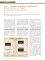
INDUSTRY
PART I: Understanding Calibration
Regular Calibration and Repairs
Necessary for Accurate Operations
b y
W a l t e r
S h a w l e e
2
Editor’s Note: This is Part I of a two-part series exploring calibration of equipment. Part I of the series focuses on the
necessity of calibration and repairs for accurate operations.
E
Illustration by Larry Stewart
very electronic device ever
designed has issues of component drift and change, as well
as the usual wear-out, damage and
failure modes. To avoid these problems impacting avionics work, regular
calibration and repairs are necessary to
ensure accurate operation.
In addition to regular calibration
cycles, it is important to develop
a solid daily self-check routine to
validate equipment before beginning
work. This daily check strategy is one
of the best contributions of ISO 9000
techniques to the avionics world, and
it can truly help an operation if implemented wisely.
Fortunately, an avionics shop does
62
avionics news
•
september
2008
not need to embrace the full nightmare
of ISO 9000 certification to get the
benefits of a quick daily performance
verification. To learn more about ISO
9000 techniques, visit the International
Organization for Standardization at
www.iso.org.
Simple Daily Checks
A simple check for using any DMM
(digital multi-meter) is to short the
leads and check for zero ohms (this
confirms the leads are good and considerable circuitry is working).
Then, check a 9V battery on possible DC voltage scales and a 1K ohm
precision resistor on possible scales.
Use the 9V battery and resistor in
series to do a simple 9mA current test,
and the 115VAC line voltage for an
AC voltage test.
If values are good (keep a log and
use the same battery and resistor), it is
good to go for the day with about 95
percent confidence.
A known good current source to add
a better current test (a current limited
power supply is ideal) allows a more
precise check if current is an important
daily parameter. When a value out of
the expected range is seen, crosscheck the source with a second instrument. If the source is good, note the
problem, then send the suspect DMM
for calibration or repair. This prevents
the day’s work being performed with a
bad instrument.
If your meter shows the “Low
Battery” or similar weak battery message, immediately replace the internal
battery and re-check. Normally, calibration is not affected by this battery
change, but operational accuracy can
be affected.
More complex equipment can be
checked together (counter to signal
generator, signal generator to scope,
etc.) with a simple test or reference
setting to ensure operation before
daily work begins. Getting into this
habit prevents serious problems with
the day’s work and ensures a higher
quality of general operations. It also
quickly catches equipment defects
before they can influence any external
avionics system work.
Understanding Accuracy,
Precision, Resolution,
Uncertainty
“Accuracy” is a measure of how
close you are to a known standard
reference; it is generally expressed in
terms of percent or some unit value
tolerance. “Precision” is not the same;
it is the degree of resolution possible
with an instrument or device.
An instrument can be precise without being accurate, and vice-versa, as
they are measures of different qualities. For example, a ruler with divisions only every quarter of an inch
is not very precise, but it can be very
accurate. A digital multi-meter with
4 ½ digits of resolution has considerable precision, but in fact, might have
terrible accuracy in terms of the measured value, rendering its “precision”
irrelevant.
For a good explanation of the difference between these two terms, visit
http://en.wikipedia.org/wiki/Accuracy.
The “resolution” of a measurement
is a reflection of how finely the distinct values will be displayed; it is the
numerical expression of the device’s
precision. For example, a simple digital meter reading 0-1.00VDC has a
resolution of 1 percent or one part
per 100. If the display is 1.000VDC,
the resolution increases to 0.1 percent
or one part per 1,000, but it implies
nothing about real accuracy, only the
granularity of the measurement.
Because all digital measurements
implicitly have a quantization error
(A-to-D conversion uncertainty) of at
CALIBRATION Q&A
Q: How accurate is my equipment?
A: Some instruments can be inaccurate by design. Consider this: A 3 ½ DMM
implies tit can resolve one part in 1,999; or, if thought of in terms of 1V, one part in a
1,000 or 0.001, which is 0.1 percent of full scale expressed as 1 volt.
An instrument can be inaccurate in an absolute sense and still be “within calibration.” For example, a meter with a full-scale accuracy of 0.3 percent on DC, and a +/- 1
digit uncertainty is still “within cal” if it reads 1.004 or 0.996 on the 1 volt DC scale. This
spread of values could be seen within your lab (a spread of .008V) between different
instruments, and everything still be “within cal” for a spec of 0.3 pecent and a 1 digit
uncertainty. If the scale is actually 3.2V FS, the error at 1 volt DC can be 1.010 and still
be at the limit of calibration, although the error is 1 percent of the displayed value.
least plus or minus one significant figure, it means those same displays have
an implicit error of at least 1 percent
and 0.1 percent on top of any basic
accuracy problems.
Accuracy is a measurement of how
closely the displayed value is to the
known real value. Unfortunately, it can
be expressed in confusing ways. From
a quantum perspective, it can never be
any closer than the basic resolution,
but it can be far worse.
Common practice is to specify the
error in terms of the full-scale value,
such as 0.1 percent FS. However, this
can mean any measured value less
than full scale can have a much larger
absolute error than expected because
the error is not expressed in terms of
the value displayed, but rather in terms
of the full-scale range.
It is not uncommon for low-cost 3.5
or 4.5 imported DMMs to have serious
accuracy problems on AC measurements — 0.5 percent to 1.5 percent FS
is common, and errors as large as 0.5
percent FS on DC and 1 to 2 percent
FS for current. This error effectively
makes them two digital meters from a
practical perspective.
These meters also can have huge
floor specifications on top of the basic
“accuracy,” such as +/- 5 digits —
which is a complicated way of saying
they are just not very accurate.
Continued on following page
Illustration by Larry Stewart
Installers should perform “pullchecks” on crimped terminals and
lugs (no wire should come out) with
their crimping tools to ensure they are
not too worn and/or use a size gauge
to confirm their continuity test gear
and any extension cables are fully
functional. These quick daily checks
can save a world of trouble in an
installation.
avionics news
•
september
2008
63
CALIBRATION
Continued from page 63
Read all the specs carefully before
buying any test equipment, and be
certain you really understand its capabilities. Many digits do not ensure
accuracy, only more resolution.
Keep in mind, during calibration,
you have to deal not only with the
errors of the item being calibrating,
but also the errors of your own reference standards, as well as how they
were calibrated and the physical connections, temperature and other factors
involved in making the measurement.
These collective factors are referred
to as the “uncertainty” of a measurement.
Calibration is really about the reduction and control of errors and uncertainty, not their complete elimination,
which generally is not possible.
Uncertainties in calibration measurements basically are composed of
two types of variables. Type A data is
generally composed of statistical variables, such as the ability to reproduce
the results and to repeat them. Type B
data is usually the assigned statistical
probability distribution from specifications such as accuracy, resolution and
transferred measurement uncertainties.
Type A and Type B are combined
for the total uncertainty of the measurement. An example of how a cal
lab could specify its best measurement
capability as an uncertainty for 10
volts DC is: 10V ± 12 μV per Volt ±
0.5 μV. This represents the best effort
possible with its equipment and techniques, and will inevitably be further
degraded by the inaccuracy of your
own specific equipment during the
transfer calibration.
How the Calibration
Industry Functions
Many shifts have occurred in the
calibration industry during the past few
years — some driven by ISO procedures, some by profit issues, and some
64
avionics news
•
september
2008
CALIBRATION Q&A
Q: Can I calibrate items internally?
A: This is a complex issue. If you have externally validated suitable standards still
in valid calibration status and if you have established valid cal procedures based on the
manufacturer’s service manual with tolerances for them, then yes, you can internally
calibrate items of lesser accuracy.
The required accuracy of your “standard” typically is four times better than what you
wish to calibrate; 10 times is preferred. Many shops own nothing of good enough quality
transfer standard to do other lesser items; therefore, they find external calibration is the
best and most cost-effective answer.
However, investing in a few good quality instruments can permit you to reliably
and internally cal many lesser items (counters, digital multi-meters, power supplies).
Basically, any 3 ½ digital multi-meter can be a high-quality standard for calibrating a
power supply, which typically has only a 2 to 3 percent tolerance.Good practice dictates
anything used as an internal “cal standard” should be used in this function primarily at
the beginning of its cal cycle, not at the end, because accuracy can be expected to
degrade by that time.
In addition, the FAA has been insisting that “standards” be segregated from daily use
items (to preserve their integrity); so, keep that in mind in your shop planning.
Most shops have no way to calibrate complex nav system generators, spectrum
analyzers, low-level frequency generators or their own primary or transfer standards;
therefore, external calibration is clearly required in these cases. Be certain, however,
the cal facility you use actually can calibrate all functions of your nav equipment.
Because of the obscure nature of many avionics items, this is not a given, even at
high-end calibration facilities.
by staff and equipment shortages.
Today, it is important to understand
exactly what you are asking for when
sending equipment out for calibration,
and to understand how it will impact
prices and what you will receive back
when the “calibration” work is completed.
In the avionics world, the implicit
understanding when you have a radio
in for service or certification is to
return it in as close to factory-original,
accurate condition as possible — the
customer reasonably expects nothing
less.
It is not common practice in the avionics industry to return radios (especially nav gear) with errors at the
extreme specification limits and for
you to do nothing other than check and
return the radio without adjustment.
And yet, this routinely happens in
the calibration world unless you fully
understand the process.
It is also possible to have equipment
“fail” calibration and be returned to
you uncertified, when in fact, a tiny
adjustment would have prevented this.
It’s all hidden in the definition of calibration services you request.
In general, most calibration facilities will not do any adjustment if the
measured value falls within the unit
specifications, no matter how close
to the edge of the limit it might be.
Unless agreed in advance, this is the
norm, not the exception.
If “with adjustments” has been
specified, a limited time will be spent
trying to bring the instrument into the
calibration limit, but not necessarily optimized. If this is not possible
(usually by a single adjustment), the
Continued on page 66
CALIBRATION
Continued from page 64
instrument typically is said to “fail”
calibration and is shifted to “repair”
status, which is a new charge. In some
cases (depending on shop policy and
prior agreement), this can trigger a full
re-calibration with new charges.
In addition, measurement data can
be provided for incoming (as received)
and outgoing (as left) measured values,
and various certifications, accreditation and documentation levels also can
be offered. Measurement data generally is offered at an extra change, which
can be significant in some cases.
Some instruments have a flat fee
for calibration; some calibrations are
charged by time.
Sometimes, a customer’s choice is
to not adjust anything, but rather simply note the value with high precision
(this sometimes is done with frequency
standards) so aging and drift can be
plotted accurately. While there is an
argument to be made for this in some
CALIBRATION Q&A
Q: What about test cables?
A: Test cables can be the single largest source of measurement error and
repeatability problems in any shop, yet they usually are ignored — which is a huge
mistake. Test cables must be functionally tested annually (and ideally daily in your
check routines), and they should be retired as soon as any connector wear or intermittent operation is found.
Oscilloscope probes are especially easy to damage and should be confirmed as
working before each daily use with the scope cal output and the probe compensation adjusted if needed. The probe and scope must be matched and compensated
correctly for proper operation. Oscilloscope probes are not universally interchangeable.
Coax cables for RF jumpers should be of high quality for high flexibility (RG58C/U
for example, not RG58A/U if 50 ohms), with crimped ends and heat sleeve strain
reliefs to withstand repeated flexing and bending. Higher quality (lower loss) cable
must be used for microwave devices such as DMEs, transponders and GPS work.
These often have solid cores, and thus fail more often because of repeated handling.
Using a network analyzer or tracking generator and spectrum analyzer are the
easiest ways to validate coax cables and can give you the exact loss in dB at specific frequencies.
Meter leads also are highly prone to flex-related breaks; good quality leads pay
real dividends here. Repairing older “intermittent” test leads is rarely a good technique as the rest of the cable is likely to be on the verge of failure. Often the most
economical strategy is to toss them when faults are detected, unless the fault is
easily identified mechanical damage on an otherwise good condition cable.
The lost labor costs and re-work associated with damaged test cables is high, so
purging anything suspect is a smart and more economical choice.
Don’t forget every lead is a thermocouple (dissimilar metal junction), so care is
required to control low-level DC errors caused by lead connections to instruments.
This is the source of thermal EMF errors and uncertainty at low levels. It is not
normally a practical issue above 1mV, but is very significant in the uV measurement
region.
66
avionics news
•
september
2008
special instances, virtually no avionics
shop wants to receive back test gear
that is not as close to the correct value
as possible, as any other technique
becomes hard to correct for in daily
work.
Be certain to discuss with the calibration facility what you want and
expect, and be certain you understand
all the costs involved. Requesting data
is an important step in optimizing
instruments, and it allows for more
effective use if you have lesser instruments slaved to them with internal
calibrations. It also gives a clearer
picture of exactly what was checked on
the instruments.
Cost has become a critical and sometimes crippling issue for many avionics
shops.
Fees from $300 for a scope to $1,500
for a nav generator are common, and a
3.5 digit multi-meter can cost $75 to
100 or more for an annual calibration
with data.
A full annual shop calibration can
top $5K per RF workstation, which can
seriously impact revenues, especially
with those items unavailable for use
during calibration.
These issues require some good
planning to minimize their impact on
your business.
The use of redundant key items,
cross-checked and with their cal cycles
offset by six months, and master/slave
items that allow some simple internally performed cals, are becoming
an increasingly important strategies to
optimize a shop’s processes, as well
as to help control costs and equipment
availability. q
“Part II: Understanding Calibration,”
which will be published in next month’s
October issue of Avionics News, deals
with calibration standards and strategies.
If you have comments or questions
about this article, send e-mails to
[email protected].