1
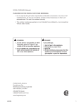
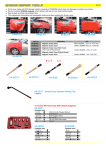
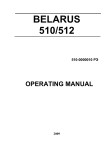
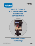
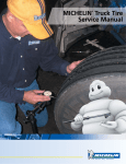
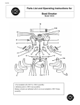
S
E C T I O N
T
H R E E
Mounting
Procedure
It is essential that good mounting procedures
be followed in order to obtain optimum tire
performance and operating efficiency. Also,
tire and rim servicing can be dangerous.
To prevent serious injury, be sure you
know, understand and follow all procedures
and safety instructions.
19
Mounting
Procedure
Mounting
Procedure
S
E C T I O N
SAFETY INSTRUCTIONS
Do not mount or demount tires
without proper training. Wall charts
containing mounting and demounting
instructions for all on-highway rims
should be available through your normal
rim supplier. “Safety Precautions for
Mounting and Demounting Tube Type
Truck/Bus Tires” are also available
through the United States Department
of Transportation, National Highway
Traffic Safety Administration,
Washington, DC 20590.
www.nhtsa.dot.gov
H R E E
LUBRICATION
Figure 3.1 Lubricate areas shown by arrows
Inspect wheel mating surfaces for chaffing, corrosion
or pitting.
WHEEL INSPECTION
GUIDELINES
Remove any and all cracked wheels
from service.
Cracked wheels not removed from
service will fail.
Inspect wheels for sometimes small cracks emanating
from stud holes.
T
Mating surfaces should be clean, smooth, and flush
so as to permit uniform distribution of clamping and
torquing forces.
These cracks will continue to grow outward, through
the “dish” or between stud holes.
Remove wheels from service with excessively worn
mating surfaces and/or worn or “wallowed” stud holes.
20
A non-water base commercial bead
lubricant should be used since water in
the tire can cause excessive rim corrosion
problems. However, thin vegetable oil
soap solutions with a water base are
approved. Lubricants which contain a
rust inhibitor can be an advantage. Avoid
the use of excessive lubricant Figure 3.1.
Never use anti-freeze, silicones,
or petroleum based lubricants.
Figure 3.2 Area of tube stretched thin due to improper
lubrication and mounting.
When a tube and flap are not properly
lubricated before mounting, they will
be stretched thin in the tire bead and
rim region Figure 3.2. This will cause
premature failure.
S
T
E C T I O N
H R E E
Area of
Excessive
Flexure
GG
Ring
Possible
Flap and
Tube Pinch
Bead
Properly
Seated
GG
Ring
Bead Not
Properly
Seated
Figure 3.3 Improper bead seating
Always use lubricant when mounting
radial truck tires to ensure proper
bead seating and to prevent eccentric
mounting. The more flexible sidewall of
the radial tire makes the use of lubricant
in the bead area more critical than for
bias ply tires which have stiffer sidewalls.
If the bead is not properly seated on
either a 2-piece or 3-piece rim and
becomes “hung-up,” usually on the
removable flange side of tube type tires,
the lower sidewall area flexes excessively
under load, and irregular treadwear and
cracking in the lower sidewall bead area
often result. Improperly seated beads
can also produce severe truck vibration
and cause chafing through the lower
sidewall down to the wire.
When the bead is not properly seated,
the bead toe is lifted, and the flap may
be forced under the toe Figure 3.3.
Continued up and down flexing of the
toe can cut through the flap. As this
process continues, the tube becomes
pinched and may fail suddenly.
TIRE & RIM CLEANING
To prepare the tire, first clean and
dry the inside with an air hose. Inspect
for loose material inside. A small piece
of paper left inside a tube type tire can
chafe a hole in the tube and cause a flat.
Dust the inside of the tire sparingly with
dry soapstone to prevent the tube from
sticking to the tire. Do not let soapstone
accumulate in the tire.
Also inspect and clean the tire beads
to remove any accumulation of corrosion
material or rubber that may be stuck to
it. Wipe the beads with a dry cloth
until clean.
Clean rims to remove dirt, surface
rust, scale and rubber build up. Repaint
to stop the detrimental effects of
corrosion and facilitate checking and
tire mounting. Be sure to clean the tire
seat areas thoroughly to insure proper
fitment of the tire and to eliminate
the potential for air leaks in tubeless
assemblies. Also file or use emery cloth
21
Mounting
Procedure
to remove any burrs or nicks on the tire
side of the rim. These may damage the
tire during mounting or in service. Be
very careful to clean all dirt and rust
from the lock ring and gutter. This is
important to secure the lock ring in its
proper position. A filter on the air
inflation equipment to remove moisture
from the air line helps to prevent
corrosion. Drain the air tank frequently.
The filter should be checked periodically
to see that it is working properly.
Check rim components periodically
for cracks. Replace all cracked, badly
worn, damaged and severely rusted
components with new parts of correct
size and type. When in doubt replace.
Mark or tag the unusable parts as scrap
and remove them from the service area.
Do not, under any circumstances,
attempt to rework, weld, heat, or braze
any rim components that are cracked,
broken, or damaged. Replace them with
new parts or parts that are not cracked,
broken, or damaged and which are of
the correct size and type.
Make sure matching parts are being
assembled. Check DOT chart, your
distributor or the manufacturer if you
have any doubts.
Mounting
Procedure
S
TUBES & FLAPS
Always install a new radial tube and a
new radial flap in a new tire. Use only
tubes designated for radials and make
sure the proper size tube and flap is used.
Never use undersized tubes. Certain
precautions must be taken when mounting
used flaps, or damage to the tire and
tube will result.
New truck and bus flaps can be used
with any one of several different tire and
rim sizes as recommended. But, once
used, the flap must be remounted in the
same size tire and on the same size rim
from which it was removed. Always use
a flap of adequate width to prevent
tube pinching.
As a precaution against flap failure,
mark the tire and rim size on the flap at
the time of removal (if inspection shows
that it is not damaged and can be used
again). When the flap is again mounted,
this marking protects against the danger
of misusing the flap with the wrong size
tire and rim.
CAUTION
Used flaps cause tube failure unless
mounted with the size tire and rim
originally used.
The valve core provides a temporary
air seal while air pressure checks are
being made, but it will leak air slowly if
the cap is loose, missing, or damaged.
Use a sealing-type valve cap. A metal
cap is preferred but a sealing-type nylon
cap is acceptable.
In the case of used tires and tubes,
recondition the valve stem every time a
tire is mounted. Recondition the threads
on both the inside and the outside of
the stem with a valve stem rethreader
tool. Install only new valve cores. Used
or dirty valve cores may be defective.
Don’t take a chance. Valve cores must
be stocked in clean closed containers at
all times, since a small particle of dirt
will render a core ineffective.
E C T I O N
T
H R E E
ASSEMBLY OF
TIRE TUBE FLAP
Insert the tube into the tire and
partially inflate it to round out the tube.
Apply rubber lubricant to the inside and
outside surfaces of both beads and to
the portion of the tube that appears
between the beads. Do not allow
lubricant to run down into the tire.
Apply the lubricant with a cloth,
swab, or brush.
For detailed, illustrated instructions
on procedures and proper use of tire
tools in mounting and demounting
Goodyear radial truck tires on various
types of rims, see the wall charts
available through RMA (www.rma.org).
After mounting and before inflating
the tire, inspect all components of
multipiece rims to make sure they are in
place. See that tires are properly mounted
and seated on the rims by checking the
distance between the tire GG ring and
the rim flange. This distance should be
the same all the way around the tire;
that is, the rim flange must be concentric
with the GG ring (refer to the photograph
Figure 3.4 below, and Figure 3.3 on
page 19, for GG ring location on tire)
and the distance must be the same for
both sides.
Figure 3.4 Use of GG ring to indicate correct mounting
WARNING
Always use a safety cage or
approved safety device and
extension hose with air gauge
and clip-on air chuck for airing
a tire on a multi-piece rim or
single piece rim.
Tube type tires should always be
aired once before the valve core is
installed. This will eliminate confusion
in inflating a tire twice. All tube type
radial tires should be inflated twice.
To inflate twice, the tire is inflated
to full inflation pressure, then all the
air is let out and the tire is reinflated.
The first inflation seats the bead of the
tire, but over stretches the tube and
flap in the area between the bead toes.
Completely deflating the tire allows the
tube and flap to relax. A partial deflation
doesn’t get the job done. The full
deflation and reinflation stretches
the tube and flap uniformly.
Important: During the first inflation,
the airing should be stopped at about 10
psi, and the side ring or lock ring should
be checked carefully to make sure it is
properly seated. Also, it is recommended
that the side ring or lock ring seating
be checked at 10 psi during the
second inflation.
WARNING
Never, under any circumstances,
attempt to seat rim components
by tapping with mallet when tire
is inflated or partially inflated.
Deflate tire first.
Install a sealing-type valve cap finger
tight. A valve cap has two functions to
perform. The first is to keep dirt from
damaging the valve core sealing surface.
The second, is to provide an air seal for
22
S
E C T I O N
T
Mounting
Procedure
H R E E
TUBELESS TIRE
MOUNTING
the valve. A valve cap, therefore, must
be durable.
The black plastic cap that sometimes
comes on a new tube is not a valve cap
and will leak air at the high inflations
used in truck tires. Its purpose is to keep
dust and dirt out of the stem during
shipment, protect the threads of the
stem, and shield the folded tube against
abrasion by the threads. The plastic cap
threads are easily stripped; the plastic
cap will crack in cold weather and will
melt if the stem comes in contact with
the brake drum. A metal valve cap
contains a rubber gasket which provides
an air seal; a plastic cap contains none.
Therefore, always use a metal cap or a
self-sealing nylon cap.
Valve extensions, or “air-through”
valves are not a substitute for caps, since
they are still subject to core seal leaks at
high pressure. Valve extensions require a
sealing-type valve cap.
Bend the valve stem to its proper
position. If it is left flat and touching
the rim, the valve cap will be difficult to
remove and accurate air pressure checks
will be hindered. (If it is easy to check
the pressure in a tire, it is more likely to
be checked.) The stem should not be
bent up enough to cause it to touch the
brake drum. Heat from the drum will be
conducted along the brass valve stem to
the tube/flap area around the stem base
and cause decomposition of the rubber.
This will lead to eventual tube failure.
In such a heated valve stem, the valve
core seal may also be ruined.
After the tire is mounted and inflated,
the tire/wheel assembly should be put
into stock for 24 hours to permit a test
of its air retention. Just prior to being
put in service, the pressure in the tire
should be checked and compared with
the initial value applied. If the pressure
is more than 5 psi lower, the tire should
be withheld from service and checked
for a leak.
For mounting tubeless tires, the
procedure is about the same as for tube
type tires except that it is not necessary
to inflate twice. Cleaning the rim is
again critical because the tire depends
on the rim for its air seal. Make sure the
inside of the tire is clean and dry. If tires
have been stored outdoors, any water in
the tire must be removed and the tire
dried before mounting. Water vapor in
the inflation air tends to cause rim
corrosion. The valve stem must be
inspected to make sure it is tight in the
rim and that the rubber grommet
between the rim and stem is in good
condition.
To install the tubeless tire on the rim,
lubricate both bead seats of the rim and
both tire beads to ensure damage-free
and uniform mounting. Bead lubricant
must also be used during demounting to
avoid damage to the bead area. Due to
their greater sidewall flexibility, it may
be necessary to use an inflation aid to
help seat radial tubeless tire beads. For
detailed mounting and demounting
instructions, refer to the wall charts
available through OSHA Occupational
Safeaty and Health Administration
(www.osha.gov). When using tire irons,
exercise caution to prevent damage to
the tire or rim.
Check that the distance between
the tire GG ring and the top of the
rim or wheel flange is uniform all
around the tire, and that the distance
is the same on both sides of the tire.
If this distance is not uniform, the
bead is not properly seated.
If the GG ring in no concentric with
the rim flange, it is recommended that
the “inflate-twice” procedure also be
used in mounting tubeless tires in order
to seat beads properly.
23
WARNING
Always use a securely held safety
cage and extension hose with
clip on air chuck for airing the
tire. Rapid air loss can propel
the assembly.
INSTALLATION
Installation of the tire on the vehicle
is the final step. When pulling a tire
from stock, check the air pressure against
the desired value. When tires are to be
mounted as duals, make sure that the
two tires are actually the same size.
(See Matching of Duals on page 25.)
Measure the outside diameter of
every tire after it is mounted and inflated
and before it goes into stock. The
diameter should be written on the tread
so that it is visible when the tire is in
the spares rack. Then by simply looking
at the treads of the spares in stock, a
replacement tire of the correct diameter
to match an already mounted dual can
be selected.
There are many ways of measuring
the size of a tire, but two ways appear
to be more satisfactory than the others.
Both involve measuring the complete
circumference of the tire. The first uses
a 14-foot endless steel mating tape.
This is a steel band that is formed into a
hoop. The hoop is slipped over the tire,
pulled up tight, and a reading made.
The second type is a pocket-size steel
tape. With this it is necessary to hook
the end in the tread and roll the tire one
revolution, which brings the tape end
back around and permits a reading of
the circumference.
Another way of measuring tires
uses calipers that measure tire diameter.
The tape method is preferred because
it provides an average diameter rather
than any one particular diameter
measurement.
Mounting
Procedure
S
E C T I O N
T
H R E E
2
1
10
7
4
5
6
3
1
8
3
6
5
4
7
2
9
8
Figure 3.6 Proper sequence for tightening stud nuts on
an 8 stud system.
Figure 3.8 Proper sequence for tightening stud nuts on
10 stud system.
DEMOUNTING
1
4
3
Figure 3.5 Measuring with pocket size steel tape.
On demountable rims, lugs should
be tightened uniformly in a triangulated
or criss-cross sequence to achieve
trueness of the rim on the wheel. Lug
nuts should be torqued properly so they
do not loosen in use. On disc wheels,
stud nuts should also be drawn up and
tightened in a criss-cross sequence.
See rim and wheel manuals for more
installation details. Lug or stud nuts
should be checked for tightness after
the first 100 miles of travel and once
each week thereafter.
2
5
Figure 3.7 Proper sequence for tightening stud nuts on
an 5 and 6 stud systems.
1
6
3
4
5
2
24
Always deflate any tire to be removed
prior to loosening rim or wheel nuts.
Bead lubricant must be used when
demounting tubeless tires.
S
E C T I O N
T
H R E E
Mounting
Procedure
MATCHING OF DUALS
Mismatched duals have the same effect
on the life of tires as low inflation or
overload. An underinflated tire on a dual
assembly shifts its share of the load to
its mate, which then becomes overloaded
and frequently fails prematurely. A
difference of 15 psi inflation may result
in the lesser inflated tire supporting 500
pounds less than the tire with the proper
inflation. A similar action occurs when
one tire’s diameter is smaller than its
mate. A difference of 1/4 inch in diameter
may result in the larger tire carrying 600
pounds more than the smaller. The shift
in load becomes more prevalent as the
difference in diameters or inflation
becomes greater.
Improperly matched duals are subject
to rapid treadwear because the larger
tire carries more load and will wear fast .
Although the mismatched duals have
different diameters, they must rotate at
the same speed. The smaller tire then
also wears unevenly because it is forced
to scuff over the road. The overall result
is abnormal and unequal treadwear for
both tires.
Improperly matched duals may also
lead to sudden air loss as a result of one
tire being required to flex severely in
doing more than its share of the work.
In addition to matching diameters and
inflation pressures on dual installations,
it is very important not to mix radials
and bias ply tires on the same axle due
to different load/deflection characteristics
of these two types of tires. Radial tires
deflect more under a given load than
bias ply tires. If radial and bias ply tires
are mixed in dual installations on the
same axle, the bias ply tires will bear
the greater part of the axle load and
may operate in an overloaded condition
that will lead to reduced mileage and
early failure.
Radial tire overall diameter will govern
the revolutions per mile obtained from
a given tire. It is necessary to closely
match tire revolutions per mile with
tandem drive axle units coupled directly
together, as when an interaxle differential
does not exist or is locked out. Otherwise,
the drive transmission may freeze up or
fail in some way, and/or excessive slip
on one of the sets of tires will lead to a
loss in traction and uneven wear.
It is important that the tires of tandem
driving axles be inspected and matched
at regular periods, as determined by the
type of service.
25
Matching dual tires is important
to insure even wear and load sharing
capabilities. Tire circumference of duals
should be as close as possible with a
maximum tire circumference tolerance
of 3/4" for tire sizes 8.25R20 and 1-1/2"
maximum circumference tolerance for
tire sizes 9.00R20 and larger.
When mounting duals on a truck,
there will generally be some difference
in the diameter of the two tires (within
the limits described above). Mount the
small tire on the inside. The outside tire
wears faster than the inside tire. As it
wears its diameter will approach that of
the inside tire. Additionally, any crown
on the road will favor the placement of
the smaller diameter tire on the inside.
At the time of mounting duals on a
vehicle, locate the two valves diametrically
opposite (180 degrees apart) for
accessibility. Hand holes on disc wheels
must be located so that the inside valve
is accessible.
Mounting
Procedure
S
T
E C T I O N
H R E E
SPACING OF DUALS
Section Width
Tire Clearance
Vehicle Clearance
Section Width
CL
CL
Spacer
Width
Proper spacing between dual tires
is important. Too often, the service
rendered by dual tires is sharply reduced
because of insufficient spacing. It is a
condition caused by either (a) oversized
tires or (b) improper rims and wheels.
Tires mounted too close together do not
allow proper air circulation to dissipate
tire heat. Heat increases tire tread loss
rate and reduces tire durability. When a
truck is heavily overloaded, insufficient
spacing can cause the sidewalls of the
duals to rub together, wear off rubber,
and become overheated due to
continuous friction.
If the space between duals is too
great, there will be excessive dragging
and scuffing of the outside tire each
time a turn is made. Also, check overall
vehicle track width to assure compliance
with width laws.
Note that proper dual spacing for
radial tires is the same as for bias ply.
An understanding of the geometry
of a dual tire installation is important.
A cross-section through a typical dual
installation is shown in Figure 3.9.
The dual spacing of the installation is
the sum of the rim offsets and the
spacer width.
To determine tire clearance, subtract
the section width from the figure for
dual spacing. Use the loaded section
width (LS) at rated load for a more exact
clearance figure. The loaded section
width can be found in the Goodyear
Truck Tire Engineering Data Book, or
the width of a tire can be measured
under load.
Dual spacing and tire clearance can
be varied by changing spacer width.
To increase spacer width, however, the
mounting width on the dual wheel must
be great enough to accommodate a
wider spacer. The distance from the
outside tire wall of one dual assembly to
the outside tire wall of the assembly on
the other side of the truck will be made
greater when spacer width is increased.
If this distance is the maximum width of
the vehicle, state laws governing truck
width must be considered.
Offset
Offset
Dual Spacing
Figure 3.9 Cross-section through typical dual installation
Rim offset determines dual spacing
and affects vehicle clearance and possibly
overall vehicle width. Any change in
offset of the inside rim will change
vehicle clearance proportionally. Any
offset changes of the outside rims will
change the overall distance across the
vehicle from outside tire wall to outside
tire wall.
Both load and inflation must be
considered in selecting rim size or
type. Consult rim manufacturer for
recommended rim style for extra ply
rating tires.
26
SPACERS
Spacer installation procedure is as
follows:
1. Examine spacer brand to be sure it
is not damaged, bent, or distorted.
It should be perfectly circular.
2. Do not roll vehicle, wheels, axle,
or assemblies on spacers.
3. Position inside rim over cast spoke
wheel as close as possible to the
mounting level.
4. Push spacer band over cast spoke
wheel with consistent pressure on
both sides. Avoid cocking band.
Achieve snug fit against spokes and
inside rim gutter edge.
5. Turn spacer band on wheel to check
concentricity.
6. Position outside rim, install outer
rim clamps and tighten nuts
evenly. Tighten nuts gradually in
a criss-cross sequence across the
diameter of the wheels. Consult
rim manufacturer’s recommendations
for proper torque range.
7. Examine clamps to be sure they
have not bottomed out. Check rim
edges to be sure they consistently
meet the spacer band edges.
8. After road service, recheck torque.
S
E C T I O N
T
Mounting
Procedure
H R E E
PROPER MATCHING
OF RIM PARTS
CORRECT
Accuride 5˚ or Motor Wheel “CR” or “FL” Flange
Motor Wheel or Accuride “CR” or “FL” Side Ring
Motor Wheel or Accuride
“CR” or “FL” Lock Ring
Proper Fit
Proper Fit
Motor Wheel or Accuride “CR” or “FL” Base
Motor Wheel LW and LB Base
Accuride or Budd LB Base
Motor Wheel LW Side Ring
Accuride or Budd LB Side Ring
Proper Fit
Motor Wheel or Accuride “CR” and “FL” Bases and Components Interchangeable With Accuride “CR” and “FL”
Motor Wheel “LB” Bases and Components Interchangeable With Accuride and Budd “LB”
INCORRECT
Accuride 5˚ Lock Ring
“CR” / “FL” Side Ring
“LW” or “LB” Base
Bead Seat Too High
“CR” or “FL” Base
Bead Seat Too High
Loose Fit
Improper Seating
“CR” or “FL” Flange & Lock Ring
“LW” or “LB” Base
“LW” Side Ring
“CR” or “FL” Base
Loose Fit
Improper Seating
Figure 3.10 Correct and incorrect matching of rim parts
Most highway rims look alike, but all
vary somewhat in certain construction
features. Variances between rims of
different types make part mixing
hazardous. A close, proper fit between
rim parts is essential to long tire life as
well as operating safety. Although side
rings, flanges, and lock rings of different
types appear to be properly seated,
difficult to detect gaps are often present.
The illustrations in Figure 3.10
show correct, safe matchings of rim
parts. Mismatched rings and bases,
which almost always create an unsafe
operating condition are also shown. For
more information, refer to Department
of Transportation (DOT) Multipiece
Rim/Wheel Matching Chart.
(www.dot.gov)
In addition to the safety problems
posed by mismatched rings and bases,
mismatched components can cause special
problems in tire, flap, and tube wear.
Mismatched rim components that
result in a high bead seat often achieve
bead seating over only a portion of the
rim circumference. This causes:
• Vibration
• Uneven wear
• Severe rim chafing at top of flange
• Larger gaps in two piece rim flanges
which cut chafer
• Torn chafers at bead heel
• Cut bead heels, which generally
identify this condition
• Bead base irregular chafing
• Lower sidewall separation due to
stress concentration at flange top
• Broken beads
27
Mismatched assemblies that result
in a low bead seat can sometimes be
recognized by rust on the bead face.
Such assemblies allow:
• Irregular bead base wear
• Off-center mounting, higher
imbalance, more vibration
• Rotational slippage of tire on rim
• Valve stem tear-outs
Rim component mismatch — with
either high or low bead seat diameter —
permits bead rocking which can cause
the tire bead toe to cut through the
flap and tube. This additional bead
movement can also cause the flap edge
to cut through the tube. In either case,
a flat tire is the eventual result.
Mounting
Procedure
S
T
E C T I O N
H R E E
SAFETY PRECAUTIONS
Inspection: Precautions And Reasons For Precautions
• Clean rims and repaint to stop
detrimental effects of corrosion and
facilitate checking and tire mounting.
Be very careful to clean all dirt and
rust from the lock ring and gutter.
This is important to insure that the
lock ring seats in its proper position.
A filter on the air inflation equipment
to remove the moisture from the air
line helps prevent corrosion. The filter
should be checked periodically to see
that it is working properly.
Parts must be clean for a proper fit —
particularly the gutter section which
holds the lock ring in proper position.
• Components that are cracked, badly
worn, damaged, bent, repaired, or pitted
from corrosion must not be used and
must be discarded. When component
condition is in doubt, replace.
Parts that are cracked, damaged or
excessively corroded are weakened.
• Do not, under any circumstances,
attempt to rework, weld, heat, or braze
any rim components that are cracked,
broken, or damaged. Replace with
new parts or parts that are not cracked,
broken, or damaged and which are
of the same size and type and are
compatible with the other parts.
Heating may weaken a part to the
extent it is unable to withstand forces
of inflation or operation.
• Make sure correct parts are being
assembled. Check your distributor
or the manufacturer if you have
any doubts.
Mismatched parts may appear to fit,
but when the tire is inflated may fly
apart with explosive force sufficient
to cause serious injury or death.
28
• Don’t be careless or take chances.
If you are not sure about the proper
mating of rim and wheel parts, consult
a rim and wheel expert. This may be
the tire man who is servicing your
fleet, the rim and wheel distributor
in your area, or the manufacturer’s
sales engineer.
Failure to exercise proper care can
result in serious physical injury
or death.
• Don’t reinflate a tire that has been run
flat or has been run at 80 percent or
less of its recommended operating
pressure, or when there is obvious or
suspected damage to the tire or wheel
components.
Components may have been damaged
or dislocated during the time the tire
was run flat or seriously underinflated.
S
E C T I O N
T
H R E E
Mounting
Procedure
MOUNTING AND INFLATION:
Precautions For Potential Steel Cord Fatigue Damage
Underinflated truck tires can be subject
to cord fatigue in the upper sidewall area
caused by over-flexing of the tire. This
cord fatigue leads to a loss of strength of
the ply cords. When a tire loses air and
is continued in service without remedial
action, it may sustain internal damage
that could lead to failure upon reinflation
or subsequent service. When such a
tire is reinflated, or removed from the
rim (for example, for tire repair or
maintenance) and then remounted,
inflation used to bring the tire to its
operating pressure may cause one or
more of the weakened cords to break.
This cord failure causes an increase in
tension on cords adjacent to the broken
cord, with the result that more of the
weakened cords may fail. This breakage
may continue until a rupture occurs in
this area of the tire with accompanying
air loss, which is commonly referred to
as a Zipper Rupture.
Permanent tire damage due to
underinflated operation cannot always
be detected. Any tire known or suspected
to have run at 80% or less of normal
operating inflation pressure could possibly
have permanent structural damage and
should be treated as having been operated
flat or underinflated. The tire should be
demounted using proper precautions and
should not be reinflated until the tire is
carefully inspected by a trained technician
for determination of the cause of the
inflation loss, and any possible strucural.
damage. (See pages 29 - 31)
GOODYEAR STRONGLY
RECOMMENDS THAT:
• Truck tires should be visually inspected
daily for cuts, snags, penetrations or
puncturing objects.
• Proper tire inflation be maintained.
• Highway truck tire inflations be
checked at least weekly, or more
frequently if operating conditions
dictate, using an accurate calibrated
air gauge.
• Any tires suspected to have been
operated underinflated must be clearly
marked and segregated, so as to
prevent their accidental use prior
to being thoroughly inspected by
a trained tire technician.
• Tires that show discoloration and
wrinkling of the innerliner, and/or
weakness and distortion of the upper
sidewall (indications of damage due
to underinflation) are to be scrapped.
• After servicing the tire, inflate it to
20 psi OVER recommended operating
pressure in an APPROVED SAFETY
CAGE USING A CLIP-ON CHUCK,
EXTENSION HOSE AND PRESSURE
REGULATOR. Allow the tire to remain
overinflated for 20 minutes and then
deflate to the recommended operating
pressure BEFORE removing from the
safety cage.
29
• Goodyear’s long-standing policy
and Occupational Safety and
Health Administration (www.osha.org)
Standard 1910.177, require that all
tubeless and tube type truck tires be
inflated in an OSHA approved
inflation safety cage in conjunction
with the use of an extension air hose
equipped with a clip-on air chuck.
• While this OSHA standard pertains
to medium truck tires, Goodyear
strongly recommends these procedures
be used for all LIGHT TRUCK
tires also.
UNLESS THE PRECAUTIONS
NOTED ABOVE ARE CAREFULLY
AND COMPLETELY FOLLOWED,
SUCH FAILURE MAY CAUSE
SERIOUS PERSONAL INJURY
OR DEATH.
Mounting
Procedure
S
E C T I O N
T
H R E E
MOUNTING AND INFLATION:
Precautions And Reasons For Precautions
• Always match a tire (size) diameter
designation with exactly the same rim
diameter designation. Don’t assume
that it came in with proper size.
• Rims of different diameters and tapers
cannot be interchanged.
• Don’t try to seat rings or other
components by hammering while tire
is inflated or partially inflated.
• Never introduce a flammable substance
into a tire — before, during or
after mounting.
Doing so is unsafe and may result in
internal tire damage or fire, rim
damage or a potentially dangerous
vapor remaining in the tire. Any of
these conditions could cause serious
personal injury during the mounting
and inflating procedure.
• Double check to make sure all
components are properly seated
prior to and after inflation.
• Always inflate in a safety cage or
use another restraining device that is
approved by the Occupational Safety
and Health Administration
(www.osha.gov).
• Don’t inflate a tire before all
components are properly in place.
Place assembly in a safety cage or use
another restraining device and inflate
to approximately 10 psi. Recheck
components for proper assembly.
Observe that the O-ring does not roll
out of its groove. If the assembly is
not proper, deflate and correct. Never
hammer on an inflated or partially
inflated tire/rim assembly. If the
assembly is proper at approximately
10 psi, continue to inflate to fully seat
the tire beads.
If tube type, inflate tire to
approximately 75 psi pressure
(Grader, 50 psi). Then completely
deflate to remove buckles and uneven
stresses from the tube and flap before
reinflating to correct operating pressure.
This repeat inflation is necessary to
prevent buckles which may lead to
premature tube failures.
After completing inflation, check
valve and rim components in both
bead areas for leaks. Observe tire
lower sidewall circumferential groove’s
concentricity with top of flange. If the
distance between the groove and rim
flange varies by 1/8'' or more around
the circumference or from one bead
to the other, the tire beads must
be unseated from the bead seat,
relubricated and reseated.
• Never sit on or stand in front of, or
over, a tire and rim assembly that is
being inflated. During inflation, always
use a clip-on chuck with sufficient
length of hose to permit standing
clear of the potential trajectory of the
wheel components, and use an in-line
valve with gauge or a pressure regulator
preset to a desired value when inflating
a tire. When a tire is in a restraining
device, do not lean any part of your
body or equipment on or against the
restraining device.
If parts are improperly installed they
may fly apart with explosive force
sufficient to cause serious injury or
death. Rapid air loss can propel
an assembly.
30
• Follow recommended mounting,
demounting, inflating and deflating
procedures for tires and rims as
outlined in this manual.
Misassembled parts may fly apart
during inflation: check at 10 psi to
determine whether parts are in
proper position.
• Don’t hammer on rims or components
with steel hammers. Use rubber, lead,
plastic or brass faced mallets if it is
necessary to tap uninflated components
together. Mallet faces should be in
good condition to avoid chips from
mallet face inside of the components.
Properly matched and assembled
components will seat without tapping.
If a part is tapped, it or the tapping
tool may fly out with explosive force.
• When moving a tire or wheel with
a cable or chain sling, stand clear.
The cable or chain may break, lash
out and cause serious injury.
• Never attempt to weld on an
inflated tire/rim assembly or on a
rim assembly with a deflated tire.
Heat from welding will cause a sudden,
drastic increase in pressure, often
resulting in a large, explosive force.
Deflated tires can catch fire inside the
air chamber.
• Mixing parts of one type rim with those
of another is extremely dangerous.
Always check manufacturer for
approval if in doubt.
S
E C T I O N
T
Mounting
Procedure
H R E E
OPERATION:
Precautions
And Reasons
For Precautions
• Always use rims recommended for the
tire. Consult catalogues for proper
tire/rim matching.
• Don’t overload or overinflate tire/rim
assemblies. Check for adequate rim
strength if special operating conditions
are anticipated.
Excessive overload or overinflation
can cause damage to the tire and
rim assembly.
• Never run a vehicle on one tire of
a dual assembly.
The carrying capacity of the single tire
and rim is dangerously exceeded, and
operating a vehicle in this manner can
result in damage to the rim and tire or
cause a tire fire.
• Never use a tube in a tubeless tire/rim
assembly where the rim is suspected
of leaking.
Loss of air pressure through fatigue
cracks or other fractures in a tubeless
rim warns you of a potential rim failure.
This safety feature is lost when tubes
are used with leaking rims. Continued
use may cause the rim to burst with
explosive force.
• Always inspect rims and wheels for
damage during tire checks.
Early detection of potential rim
failures may prevent serious injury.
• Never add or remove an attachment
or otherwise modify a rim (especially
by heating, welding or brazing) unless
the tire has been removed and
approval has been received from
the rim manufacturer.
Modification or heating of a rim or
one of its parts may weaken it so that
it cannot withstand forces
created by inflation or operation.
SERVICING TIRE AND RIM
ON
VEHICLE:
Precautions And Reasons For Precautions
• Block the tire and wheel on the
opposite side of the vehicle before
placing the jack in position.
• Regardless of how hard or firm the
ground appears, put hardwood blocks
under the jack. Always provide for
vehicle support with blocks just in
case the jack should slip.
The vehicle may shift, slip off the jack
and cause injury.
Inspection Procedures For Identification
Of Potential “Zipper Ruptures” In Steel Cord
Radial Medium And Light Truck Tires
Any tire suspected of having been
operated underinflated and/or overloaded
must be approached with caution.
Completely deflate the tire by removing
the valve core before removing the
tire/rim/wheel assembly from the
vehicle. After removing from the vehicle,
clearly identify the tire, so it will not be
reinflated until carefully inspected by a
trained technician, to determine the
cause of inflation loss, as well as any tire
damage resulting from underinflation
and/or overloading.
31
WARNING
Permanent tire damage due to
underinflation and/or overloading
cannot always be detected. Any
tire known or suspected to have
been run at 80% or less of normal
operating inflation pressure and/or
overloaded, could possibly have
permanent structural damage
(steel cord fatigue). Ply cords
weakened by underinflation
and/or overloading may break
one after another, until a rupture
occurs in the upper sidewall with
accompanying instantaneous air
loss and large explosive force.
This can result in serious injury
or death.
Mounting
Procedure
S
E C T I O N
T
H R E E
Inspection Procedures For Tires Suspected Of
Having Been Run Underinflated And/Or Overloaded
A
Inspect Deflated
Suspect Tires Mounted
on the Rim –
LOOK for:
cuts, snags, or chips exposing body
cords or steel*; distortions or undulations
(ripples and/or bulges), using an indirect
light source, which will produce shadows
left by any sidewall irregularities.
FEEL for:
soft spots in the sidewall flex area;
distortions or undulations (ripple and/or
bulges); protruding filaments indicating
broken cords; and
LISTEN for:
any popping sound when feeling for
soft spots or when rolling the tire.
If any of these conditions are present,
the tire should be made unusable and
scrapped. *If no other condition is
present and a tire contains cuts, snags,
or chips exposing body cords or steel,
it must be referred to a full-service
repair facility, to determine if it is
repairable and not a source of a
potential zipper.
If none of these conditions are present,
place the tire/rim/wheel assembly in
an approved inflation safety cage.
REMAIN OUTSIDE OF THE TIRE’S
TRAJECTORY. DO NOT PLACE
HANDS IN SAFETY CAGE WHILE
INSPECTING TIRE, OR PLACE
HEAD CLOSE TO SAFETY CAGE.
With the valve core removed, reinflate
the tire to 20 psi, using a clip-on air
chuck with a pressure regulator and
an extension air hose.
B
Inspect Suspect
Tire Inflated
to 20 psi —
LOOK for:
distortions or undulations (ripples
and/or bulges); and
LISTEN for:
any popping sound.
If any of these conditions are present,
the tire should be made unusable
and scrapped.
If none of these conditions are
present, dismount the tire to visually
and manually inspect it, both inside
and outside.
C
Inspect Suspect
Tires after
Dismounting —
LOOK for:
bead rubber torn to the fabric or
steel*; cuts, snags, or chips exposing
body cords or steel*; distortions or
undulations (ripples and/or bulges),
using an indirect light source, which will
produce shadows left by any sidewall
irregularities; creasing, wrinkling,
cracking or possible discoloration of
the innerliner; and any other signs of
weakness in the upper sidewall.
If any of these conditions are
present, the tire should be made
unusable and scrapped. *If no other
condition is present and a tire contains
cuts, snags, or chips exposing body
cords or steel, it must be referred to a
full-service repair facility, to determine
if it is repairable and not a source of a
potential zipper.
If none of these conditions are
present, the tire may be returned to
service, using the procedures on the
next page.
WARNING
STAY OUT OF TRAJECTORY AS
INDICATED BY SHADED AREA.
Note: Under some circumstances,
the trajectory may deviate from its
expected path. Always deflate tires
before handling. Inflate only in
safety cage.
32
S
E C T I O N
T
Mounting
Procedure
H R E E
Inspection Procedures For All Tires Returning to Service (Including
used, retreaded, or repaired, regardless of being suspect or not suspect)
A
Inspect Dismounted
Tires (including
used, retreaded,
or repaired)–
LOOK for:
bead rubber torn to the fabric or steel*;
cuts, snags or chips exposing body cords
or steel*; distortions or undulations
(ripples and/or bulges), using an indirect
light source, which will produce shadows
left by any sidewall irregularities; creasing,
wrinkling, cracking, or discoloration
of the innerliner; any other signs of
weakness in the upper sidewall;
FEEL for:
soft spots in the sidewall flex area;
distortions or undulations (ripples
and/or bulges); protruding filaments
indicating broken cords; and
LISTEN for:
any popping sound when feeling for
soft spots or when rolling the tire.
If any of these conditions are present,
the tire should be made unusable and
scrapped. *If no other condition is
present and a tire contains tears, cuts,
snags, or chips exposing body cords
or steel, it must be referred to a fullservice repair facility, to determine
if it is repairable and not a source of
a potential zipper.
If none of these conditions are present,
place the tire/rim/wheel assembly in
an approved inflation safety cage.
REMAIN OUTSIDE OF THE TIRE’S
TRAJECTORY. DO NOT PLACE
HANDS IN SAFETY CAGE WHILE
INSPECTING TIRE, OR PLACE
HEAD CLOSE TO SAFETY CAGE.
After properly seating the beads, with
the valve core removed, adjust the tire
to 20 psi, using a clip-on air chuck with
a pressure regulator and an extension
air hose.
B
Inspect Mounted
Tires Inflated
to 20 psi —
LOOK for:
distortions or undulations (ripples
and/or bulges); and
LISTEN for:
any popping sound.
If any of these conditions are present,
the tire should be made unusable
and scrapped.
If none of these conditions are present,
with valve core still removed, inflate the
tire to 20 psi OVER the recommended
operating pressure. During this step,
if any of the above conditions appear,
immediately stop inflation.
C
Inspect Mounted Tires
Inflated 20 psi OVER
Operating Pressure —
LOOK for:
distortions or undulations (ripples
and/or bulges): and
LISTEN for:
any popping sound.
Any tire suspected of having been
underinflated and/or overloaded must
remain in the safety cage at 20 psi
OVER operating pressure for 20 minutes.
If any of these conditions are present,
the tire should be made unusable
and scrapped.
If none of these conditions are present,
BEFORE removing the tire/rim/wheel
assembly from the safety cage, reduce
the inflation pressure to the recommended
operating pressure. REMAIN OUTSIDE
OF THE TIRE’S TRAJECTORY.
Occupational Safety and Health Administration
Standard 1910.177 requires all tubeless and tube-type
medium and large truck tires be inflated using an
OSHA-approved restraining device (e.g. safety cage)
or barrier, and using a clip-on air chuck with a
pressure regulator and an extension air hose. While
the OSHA (www.osha.gov) standard pertains to
medium and large truck tires, RMA also strongly
recommends these procedures be used for all LIGHT
TRUCK TIRES.
WARNING
Mounting Tires Is Dangerous failure to follow the above and
Rubber Manufacturer‘s Association
(RMA) “Demounting and Mounting
Procedures for Truck/Bus Tires”
or “Demounting and Mounting
Procedures for Automobiles and
Light Truck Tires” charts and safety
precautions can result in serious
injury or death. For more information
visit www.rma.org.
33