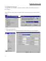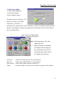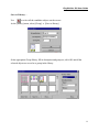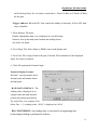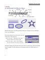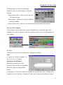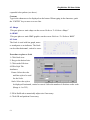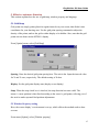
1
EasyView500
32BIT RISC CPU
Professional Human Machine Interface
??MT508S / MT506S / MT506L
User Manual
Weintek Labs., Inc.
EasyBuilder 500 User Guide
1.
STARTUP ................................................................................................................................................ 5
1.1 THE FIRST STEP ........................................................................................................................................5
1.2 EASY BUILDER SCREEN EDITOR FUNCTIONS........................................................................................8
1.3 CREATING A NEW PROJECT ....................................................................................................................10
2.FUNDAMENTALS .....................................................................................................................................20
2.1 ID NUMBERS...........................................................................................................................................21
2.2 A TTACHING A DESCRIPNTION................................................................................................................21
2.3 ENTERING PLC READ/WRITE ADDRESS ...............................................................................................21
2.4 SELECTING A SHAPE...............................................................................................................................23
2.5 SELECTING A BMP.................................................................................................................................24
2.6 CREATING LABELS .................................................................................................................................25
2.7 P ROGRAMMING TASK BUTTONS...........................................................................................................28
2.8 W INDOWS................................................................................................................................................31
2.9 W INDOW SELECTION BAR ....................................................................................................................35
2.10 A DD A SHAPE TO THE LIBRARY ...........................................................................................................36
2.11 A DD BMP TO THE LIBRARY ................................................................................................................37
2.12 GROUP LIBRARIES................................................................................................................................37
3. PARTS ...........................................................................................................................................................40
3.1 BIT LAMP.................................................................................................................................................40
3.2 W ORD LAMP ...........................................................................................................................................41
3.3 SET BIT ....................................................................................................................................................42
3.4 SET W ORD...............................................................................................................................................44
3.5 TOGGLE SWITCH.....................................................................................................................................47
3.6 M ULTI-STATE SWITCH ...........................................................................................................................48
3.7 FUNCTION KEY........................................................................................................................................49
3.7.1 Change Window...........................................................................................................................50
3.7.2 Return to Previous.......................................................................................................................50
3.7.3 Change Common Window ..........................................................................................................50
3.7.4 Character Codes and Creating a Keypad................................................................................50
3.7.5 Move Window ...............................................................................................................................51
1
EasyBuilder 500 User Guide
3.7.6 Minimize Window.........................................................................................................................52
3.7.7 Popup Window..............................................................................................................................52
3.7.8 Close Window...............................................................................................................................52
3.7.9 JOG FS-Window ..........................................................................................................................53
3.7.10 Message Board...........................................................................................................................53
3.8 M OVING SHAPE ......................................................................................................................................54
3.9 A NIMATION..............................................................................................................................................56
3.10 NUMERIC INPUT ...................................................................................................................................58
3.11 NUMERIC DATA ....................................................................................................................................63
3.12 ASCII INPUT .........................................................................................................................................64
3.13 ASCII DATA..........................................................................................................................................66
3.14 BAR GRAPH...........................................................................................................................................67
3.15 M ETER...................................................................................................................................................69
3.16 INDIRECT W INDOW ..............................................................................................................................70
3.17 DIRECT W INDOW .................................................................................................................................72
3.18 A LARM SCAN........................................................................................................................................74
3.19 A LARM DISPLAY...................................................................................................................................75
3.20 TREND DISPLAY ....................................................................................................................................77
3.21 A LARM BAR ..........................................................................................................................................80
3.22 RECIPE TRANSFER................................................................................................................................81
3.23 EVENT DISPLAY....................................................................................................................................83
3.24 DATA TRANSFER...................................................................................................................................85
3.25 EVENT LOG ...........................................................................................................................................87
3.26 PLC CONTROL .....................................................................................................................................89
3.27 SYSTEM MESSAGE ...............................................................................................................................91
4. DRAWING...................................................................................................................................................92
4.1 LINE/RECTANGLE/CIRCLE /ELLIPSE /A RC/POLYGON .........................................................................92
4.2 TEXT.........................................................................................................................................................93
4.3 SHAPE.......................................................................................................................................................94
4.4 BMP.........................................................................................................................................................94
4.5 S CALE.......................................................................................................................................................94
2
EasyBuilder 500 User Guide
5. EFFECTIVE ASSISTANCE FUNCTION..........................................................................................95
5.1 GRID/SNAP ..............................................................................................................................................95
5.2 W INDOW PROPERTY SETTING...............................................................................................................95
5.3 LANGUAGE ..............................................................................................................................................96
5.4 OBJECT ATTRIBUTE................................................................................................................................96
6. EDIT FUNCTIONS ...................................................................................................................................97
6.1 SELECTING OBJECTS..............................................................................................................................97
6.2 M OVE OBJECTS.......................................................................................................................................97
6.3 A LIGN OBJECTS......................................................................................................................................97
6.4 S CALE OBJECTS......................................................................................................................................97
6.5 GROUP /UNGROUP OBJECTS..................................................................................................................98
6.6 BRING TO FRONT / SEND TO BACK .......................................................................................................98
6.7 CHANGE CHARACTER SIZE....................................................................................................................98
6.8 CUT, COPY AND PASTE..........................................................................................................................98
6.9 CHANGING ATTRIBUTES ........................................................................................................................98
6.10 UNDO .....................................................................................................................................................98
6.11 REDO ......................................................................................................................................................98
6.12 RESIZING OBJECTS...............................................................................................................................99
APPENDIX I - PARTS (OBJECTS) SUMMARY...............................................................................100
APPENDIX II – ERROR MESSAGE ....................................................................................................102
3
EasyBuilder 500 User Guide
4
EasyBuilder 500 User Guide
1. Startup
1.1 The First Step
Set up the MT500 with PC and PLC as depicted below.
a) connect PC[RS-232] port of the MT500 to the PC. Since the PC[RS-232] and
PLC[RS-485] share the same D-SUB connector , it is recommend to use MT5_PC to
split it into two separate connectors at debug process.
b) connect either PLC[RS-485] or PLC[RS-232] port of the MT500 to the PLC. (Please
check the PLC signal type and cable listing in the back of this manual to assure proper
port connections.)
MT510
Reset Button
Dip Switch
Reset Button
Contrast
Contrast
Dip Switch
MT506
PLC(RS-485)
PC (RS-232)
PLC(RS-232)
PLC(RS-485)
PC (RS-232)
PLC(RS-232)
PRINTER
MT5_PC cable
PC
To PLC
To PLC
RS-485 Interface
RS-232 Interface
c) Set Dip Switch at all “OFF” position (factory default setting).
5
EasyBuilder 500 User Guide
d) Connect DC 24V power to the power connector. Fail to connect the right pole may
cause fuse in the MT500 burn out.
e) Apply power and calibrate contrast adjust VR to the best viewing performance. (For
MT500S only, not applicable for MT500T)
f) Install EasyBuilder 500 on your PC and enter EasyManager after you finish the
installation process.
The Easy Manager is a software shell program for
EasyBuilder : screen editor to configure EasyView MT5xx
HMI (abbreviated as EB500).
EasyWindow: simulate EasyView on the PC, after the
project is complied by EB500(file with extension *.eob),
the EasyWindow will retrieve the data from PLC through
the EasyView and simulate the operation of EasyView on
the PC screen. Using the Simulator on your debug process
will save on time spent in repeat downloads.
EasyView communicator: download/upload project and
switch operation mode.
Download :Download the project complied by EB500 to the EasyView.
Upload : Upload the project image from EasyView to an object file (*.eob). The
upload file cannot be opened by EB500 but can be transferred to another EasyView.
This is useful for retrieving data from installed units to make a duplicate setup.
Mode Change: The EasyView operates in three modes:
RDS (Remote Debug & Simulation) mode: Used for simulation and
download/upload.
6
EasyBuilder 500 User Guide
Application (On line operation) mode: This is the normal operating mode of the
EasyView, the EasyView will start from the startup window of the project
download.
Touch Adjust (Touch screen calibration) mode: Used to calibrate the touch
screen.
The EasyWindow and EasyView communicator can also be invoked by EasyBuilder,
however the communication setting (between PC and EasyView) is defined on the
EasyManager as follows:
COM Port : selecting the COM port that connected with the EasyView.
Comm. Speed : to determine the communication speed between the PC and the EasyView
during download and upload operations.
Project Download/Upload or Recipe Download/Upload: to determine which data is sent
or retrieved from the EasyView.
Project: All Project related files
Recipe: recipe data
Full or Partial Download/Upload: This is only for project download/upload, “Full”
means project files and application program , “Partial” means project files only.
Now click the EasyBuilder
button. The following popup
dialog appears.
Select the appropriate model
that you are programming .
7
EasyBuilder 500 User Guide
1.2 EasyBuilder Screen Editor Functions
Clicking on the Easy Manager’s [EasyBuilder] button will cause the following screen to
appear. The functions of each screen area are explained below.
a. Title bar
c. Tool bar
b. Menu bar
d. State selector
e. Alignment
f. Object resize
g. Position adjust
h. Group / ungroup
i. Layer control
j. Text size and position
k. Rotate & flip
l. Part tool box
m. Window / Object selection tree
n. Drawing tools
o. Cursor Position
a. Title Bar
Displays the project’s file name, window number and title.
b. Menu Bar
Displays the menu used to select EasyBuilder commands. Selecting one of these causes
the corresponding pull down menu to appear.
c. Tool Bar
Displays the icons corresponding to the File, Edit, Library, Compile, Simulation and
Download command.
8
EasyBuilder 500 User Guide
d. State selector
Clicking on this button toggles all the parts on the screen to a specified state.
e. Alignment
Make all the selected parts line up to the top, bottom, left or right.
f. Object resize
It makes the dimension, width or height of all the selected part to the same size.
g. Position adjust
Adjust the position of selected parts.
h. Group / ungroup
The group function makes a collection of selected parts and drawing elements as one
object.
i. Layer control
Adjust the Layer of selected part – one layer up, one layer down, to top layer and to
bottom layer.
j. Text size & position
Change the font size and alignment of the selected text.
k. Rotate and flip
Allows shapes to be flipped horizontally or vertically and rotated in 90 degree
increments.
l. Parts tool box
Icons representing each part type are shown. Clicking on one of these icons causes that
icon’s dialog box to appear. That part’s attributes can then be set and the part can be
placed on the screen.
m. Window and object selection tree
It provides a convenient way to select a window or a specified project.
n. Drawing tool
Icons representing each drawing tool are shown. Availa ble drawing tools include line,
rectangle, ellipse/circle, arc, polygon, scale, bit map graphics and shape.
o. Cursor position
Shows the current cursor position on the active window.
9
EasyBuilder 500 User Guide
1.3 Creating a new project
A project file ( .epj ) is simply a collection of all the windows and configured objects on
the windows.
In the File menu, select [New] and model of MT touch screen and a new project will be
created.
1) Fill in system parameter
In the Edit menu, select [System Parameter] and the following screen will appear.
10
EasyBuilder 500 User Guide
Within this screen, there are three tabs, [PLC] , [General] and [Indicator]. Choosing [PLC]
tag to setup parameters to link with PLC, choosing [General] tag to setup the system
configuration of the project and choosing [Indicator ] tab to set attribute of system
indicator.
PLC Tab
PLC type : select appropriate PLC type from the available PLC selection menu.
Hardware version: To select the version of the MT touch screen to which the created
project will be downloaded.
Serial port I/F : Select the port connected with PLC, either RS-232 or RS-485 .
Baud rate, Parity, Data bits and Stop bits : Set the communication parameter to match
with PLC.
MT station No. : This is used when multiple MTs can connect to the PLC link, for
example for AB DH485 or Unitelway driver, it is possible to connect multiple to the PLC
link, each MT has to be set different station No. Set it as 0 when not used.
PLC station No. : Used when PLC has a node or station No. Set it as 0 when not used.
Multiple HMI : Allows more than one MT to be connected to one PLC, even PLC has
only one communication port.
Disable : Disable chaining of multiple MT to one PLC
Master : Select this when the MT is the unit connected directly to the PLC
Slave : Select this when the MT connect to the precedence MT.
HMI-HMI line speed : Set appropriate communication speed between master MT and
slave MT, both shall set the same speed.
The EasyView is able to support master - slave communication feature for
every PLC it supports. All the EasyView are connected one by one and the first one
connects with the PLC. The one EasyView which connects directly with PLC is configured
as master. All the other EasyView which connect to preceding EasyView and retrieves PLC
data through preceding HMI are configured as slave. In theory there is no limitation for
number of EasyView on a chain, however response time will gradually decrease when
more than three EasyView are linked together in a chain.
11
EasyBuilder 500 User Guide
Wiring cable between EasyView
SLAVE HMI
PLC[RS-232] D-SUB male
2 TD
3 RD
5 GND
MASTER HMI
PC[RS-232] D-SUB female
8 RD
7 TD
5 GND
Configuration
Multiple HMI : Set “Master” for the MT500 connects with PLC, set “Slave” for
the rest of the MT500.
HMI-HMI line speed : select either 38400 or 115200 .
Note: all the EasyView in the link must set the same link speed. When [multiple HMI] is
set as “slave”, the EasyView will ignore those communication parameters connect
with PLC (serial port I/F, baud rate, ..) . It will always use PLC[RS-232] to retrieve
data from preceding EasyView.
PLC time out constant (sec.) : The parameter determine how long the MT will wait for
the response from the PLC. This setting is required when the PLC is slow in response.
Normal time out constant is set as 3.0 seconds.
PLC block pack : The MT will automatically collect all continuous PLC data and send
read command, it greatly increase efficiency of communication and improve response time.
However if data is not continuous then the MT will read it by separate commands. The
PLC block pack set allowable gap between configured addresses, even two data is not
continuous in address, however if the difference is not greater than PLC block pack then
MT still read pack those data in one command and read it from the PLC.
12
EasyBuilder 500 User Guide
General Tab
Task Button : The Task button is used to pop up the fast display window or display the
icon bar. Minimized window’s icons are put on the icon bar.
Attribute : Enables or disables this feature. If disable the fast window and task bar are
not available at run time.
Background color : select background color of the task bar.
No. of min. windows : Set the number of windows that can be minimized to the task
bar.
Position : determines the position of task button, in left or right.
Text : determines if the text displayed in the minimized window icons is centered or
left adjust.
Alarm Bar : The alarm bar rotate all the alarm message one by one .
Pixels per scroll : set the number of pixels of the alarm message to scroll ( 8, 16, 24 or
32 pixels), the larger the number the faster a given message will be displayed.
13
EasyBuilder 500 User Guide
Scroll speed : set the time interval to scroll, the smaller the number the faster the alarm
message are displayed.
Startup window No. : This is the window displayed on the screen when MT startup.
Backlight saver : The MT turn off back light if there are no touch operations in preset
time ( range 1 to 30 minutes ). Set 0 disables the backlight saver function.
Cursor color : Set the color of cursor when the Numerical Input is activated for data entry.
Buzzer : Disable or enable buzzer operation, the buzzer will activate when the touch
screen is pressed.
Common Window : Common window is a window that overlay to the base window at any
times.
Popup window : set the attribute of popup window registered in the common window,
it can be popped up as normal (i.e. the latest pop up window is always displayed on the
top.) or on the top .
Draw common window : set the common window above or below base window.
Extra. No. of Event : The MT is set to accommodate up to 1000 event. If more than 1000
event are needed, the additional number of event is entered here. For example if 1200
event messages are needed, 200 shall be entered in the Extra No. of event.
RTC source : set the source of time of date when event message is generated. The RTC
data can be retrieved from local word or internal RTC. If local word is selected then it is
necessary to set another DF (Data Transfer ) object to transfer actual RTC data from PLC
to local word periodically. If internal RTC is selected, the optional recipe card must be
installed in the CPU board.
Print: Used to set printer protocol, enable the printing of time tag and sequence number
when event message is printed out.
14
EasyBuilder 500 User Guide
Printer : select the compatible printer driver for your printer.
Print sequence number : enable the printing of a sequence number along with the
event message. The sequence number is incremented each time a new event comes up.
Print time tag: Enable the printing of time of date along with event message.
Error detection : Set to ignore error signals ( such as no paper ) from the printer or
hold transmission of printed data until error signals are cleared.
Indicator Tab
Touch Indicator: The touch indicator changes color when the screen is touched.
Attribute : Enable or disable this feature. If disabled, the touch indicator is not
displayed.
Non-configured area, Active area, Inactive area and Frame : Set color for touch
operations in each area of screen.
CPU indicator: The CPU indicator is a bar graph that shows the percentage of CPU
loading.
Attribute : Enable or disable this feature, if disabled the CPU indicator is not
15
EasyBuilder 500 User Guide
displayed.
Color : Set color of CPU indicator.
Alarm indicator: The alarm indicator is a bar graph that shows the number of alarm
message exists, the bar graph display full scale if number of alarm above ten .
Attribute : Enable or disable this feature, if disabled the CPU indicator is not
displayed.
Color : Set color of CPU indicator.
2) Select BMP and/or Shape Library to attach to the project
In the Library menu, select [Shape, BMP or Group] ? [Call up Library] to call up
library browser.
EB500 provides three types of libraries:
A Bitmap graphics (BMP) is a collection of pixel of data. EB500 supports up to 256
colors Bitmap graphics.
A Shape is a collection of drawing elements, those elements, when put together, will
define a graphic symbol representing a button, lamp, function key etc.
A Group is a collection of objects. (i.e. A keypad would be a group of function
buttons.)
Click select Lib. To
attach an existing library
to the current project
16
EasyBuilder 500 User Guide
A comparison of shape and BMP is illustrated below:
Bit Map Graphics
Shape
Arbitrary Graphic
Good
Memory capacity
Very large
Limited to those graphics can
be designed by basic drawing
elements
Small
Effect of enlarge &
shrink
Display Speed*
Fair to Bad
Good
Good
Good
The MT500’s 32 bit processor allows display speed of both bit map graphics and shapes
to be extremely fast, even during enlarge and shrink operations.
3) Design the windows
Use the parts and drawing elements, virtually any type of window display can be
competed in 10 minutes. “Easy to Use” is the greatest benefit of our EasyBuilder screen
editor software.
4) Save the project
In the File menu, select [Save] or click on icon
to save the project.
5) Compile the project
In the Tool menu, select [Compile] or click on
to compile the project file to the
image file ( .eob FILE )
17
EasyBuilder 500 User Guide
6) Simulate the project
In the Tool menu, select [Simulate] or click on
to start simulation. After the project
is complied by EB500, the Simulator will retrieve the data from PLC through the
MT500 and simulate MT500 operation. By using the Simulator before the project is
completely debugged, a lot of time will be saved by avoiding repeated downloads.
Before simulation, be sure to connect the MT500 and the PLC properly and set the
COM port in the Easy Manager menu. EB500 also supports off line simulation, the off
line simulation will not retrieve data from PLC and therefore all the data on the screen
is static.
18
EasyBuilder 500 User Guide
7) Download the project
In the Tool menu, select [Simulate] or click
to load the image file into MT500.
Before downloading, be sure to set the COM port in the Easy Manager menu.
8) Switch to Application Mode
Go back to Easy Manager, click on [Jump to
Application], the MT will enter online operation
mode and the start up screen will be displayed.
Improper programming: If the MT500 screen is
programmed to access data from an invalid register
or bit adress for the PLC, the unit receives an error
message from the PLC. The unit interprets this as a
loss in communications. Be sure that all data points
registered in the window are valid for the PLC that
is connected.
This ends the Quick Start section. From here it is up to you to make the spectacular
screen displays that will make life easier for your operators.
19
EasyBuilder 500 User Guide
2.Fundamentals
Basically, a screen is composed of a variety of parts such as Switches, Lamps, Numerical
data and Graphics. The procedure to add a part to the screen is just a simple 3 step
procedure.
Procedure to build up a Part.
1. Select a Part by either clicking on a Parts toolbox icon,
or dragging over one of the [Parts] menu’s selections.
2. Once the Parts dialog box appears, set (enter) the
Part’s attribute data, such as PLC read/write address,
shape or BMP, and label as described in this section.
3. After all of a Part’s attributes have been set, simply
click on the Finish button to place it on the current
screen. If desired, use the Part’s sizing handles to
adjust its size, or click on the Part to select it and drag
it anywhere on the screen.
A Bit Lamp
Part’s Dialog Box
20
EasyBuilder 500 User Guide
2.1 ID Numbers
An ID number is a code number that is assigned automatically to a Part. The number
identifies a specific part on the current screen. The programmer cannot change the ID
number.
WL-001
Indicate part is
Word Lamp
Sequence number
for the part
2.2 Attaching a Descripntion
If desired, a comment can be attached to a Part. This is a good practice for future
referencing and useful when deciphering a printout of project files.
2.3 Entering PLC read/write address
The valid device type and address range depends on the individual PLC type. Select
appropriate PLC type in the system parameter menu.
21
EasyBuilder 500 User Guide
The device type field will indicate all possible devices available.
Click icon show all
the possible device
Enter address here
Devices reside in EasyView Internal memory
Type
Bit
Bit
Bit
Bit
Device Name
LB
RBI
RB
Ms_RB
Range
0~9999
0h~4095h
0h~4095h
0h~4095h
Bit
Word
Word
Word
Word
Word
MS_LB
LW
RWI
RW
Ms_RW
MS_LW
0~9999
0~9999
0~4095
0~4095
0~4095
0~9999
Remark
Address of local memory
h=0~F, index address of recipe memory
h=0~F, absolute address of recipe memory
h=0~F, absolute address of Master HMI’s recipe
memory.
Address of Master HMI’s local memory
Address of local memory
index address of recipe memory
absolute address of recipe memory
absolute address of Master HMI’s recipe memory.
Address of Master HMI’s local memory
The RB is mapping to the same area as the RW, for example RB50..RB5F is
mapping to the same location as RW5, while the LB is mapping to the different
area from the LW.
The local memory address above LW9000 is reserved for system use and user shall
not use them as general purpose device.
When the recipe memory is accessed by index address, the index address is offset
from its indicated address by the content of LW9000. For examples if (LW9000)=
50, then an index address RWI 100 physically accesses the data at address RW 150
(100+50).
22
EasyBuilder 500 User Guide
2.4 Selecting a Shape
1. Click on the [Shape] tab
2. Select [Use shape]
Click on [Shape Library].
The shape browser will pop up. The
shapes are stored in a specified
shape library ( SLB file ). A
maximum of 10 shape libraries can be attached to a project. By calling up different shape
libraries, useful shapes for almost any application can be found. Users can also build up
their own shape library.
Select any shape library
attached to this project.
Select the state to view each
shape in the cell.
Each cell can have a maximum
of 32 shapes, the first shape in
the cell represent zero (0), the
second represent one(1) and so
on. Toggle state selector to
Select Lib
New Lib
Delete shape
Export
Attach an existing library to the current project
Attach a new (blank) library to current project
Delete all the shapes from the selected cell
Export the shape to current screen (return to a group of draw objects)
23
EasyBuilder 500 User Guide
2.5 Selecting a BMP
Click on the [Shape] tab
Select [Use BMP]
Click [BMP Library]
The BMP browser will pop up. The
BMP graphics are stored in a
specified BMP library ( BLB file ).
Each project is able to include 10
BMP libraries. By calling up
different BMP library, a useful
Select any Bitmap library
attached to this project.
Select the state to view
each cell’s Bitmap.
Each cell can have a maximum of
32 Bitmap graphics, the first
Bitmap in the cell represents zero
(0), the second represents one (1)
and so on. Toggle the state
selector to view each Bitmaps
BMP library for almost any application can be found. Users can also build up their own
BMP libraries.
Select Lib
New Lib
Export
Add bitmap
Delete bitmap
24
Attach an existing library to the current project
Attach a new (blank) library to current project
Save the BMP to a file with *.bmp format
Add BMP graphics to the specified cell
Delete BMP graphics from the selected cell
EasyBuilder 500 User Guide
2.6 Creating Labels
A label means the text characters shown on the face of the Switch, Lamp or other objects
(Parts).
Adding a label to a Part
1. Click on [Label] tab
2. Select Attributes for the part
3. Select the state to label
Click icon to select each state
Select “Use Label” to enable
label display
4. Type the state’s label in the Content box
State
States are displayed only for those parts with multiple states. The text displayed for each
state can be set independently. Simply select a state in order to set its text, font, color and
alignment.
25
EasyBuilder 500 User Guide
Font
A variety size of font is available – 8, 16, 24, 32, 48, 64, 72 and 96
Alignment (Justification)
When the text input for a Label becomes more than two lines, the alignment can be defined
as left, right or center justification.
Color
A maximum of 32 from 256 colors are available for selection, the “basic” palette includes
the most commonly used colors. The “customized” palette allows the user to customize his
preference color palette.
Select color icon to
customize the palette
There are two color palettes, each consists of 128 colors
Content Box
Type in the characters to be displayed on the button in the Content Box. The “ENTER” key
can be used to move to the next line if desired.
26
EasyBuilder 500 User Guide
Position
Once the Part is placed on the screen, the Label can be moved anywhere within the
boundary of the object. Just click on the label and drag the mouse to move it to the desired
position. Toggle through the state designator to display the predefined label in each state.
Click on
the object
Click on
the label
Drag to
move
27
EasyBuilder 500 User Guide
2.7 Programming Task Buttons
Task Button Overview
The EasyView 500 provides a method to pop up (maximize) or icon-ize (minimize) child
windows and change window displays.
Fast Select
Window
Expands out
Window Bar
Expands out Fast
Select Window
Window Bar
Indicators
If “Task button” is enabled, pressing the right-hand task button will pop up a fast selection
window. The fast selection window can have several function keys (placed on it by the user)
to change to different windows. Since the fast selection window is global to all windows, it
can be called up at any time. To change windows, press the function key that targets the
destination window. This avoids the tedious search and find process. The Window Bar
accommodates up to six window icons. Double -clicking the minimize icon of a window
will icon-ize the corresponding window. Clicking it again will return the window to its
original location and size.
28
EasyBuilder 500 User Guide
Procedure to Setup Task Buttons
1. On [Edit] menu ? Select
[System Parameter]. Set [Task
button] as Enable. Set the
position of the task buttons to the
left or right side of the window.
Note: The task buttons will be visible at run time in the lower right or left corner of the
display. The Task buttons are not visible when editing a window.
2. Click on the General Tab. Select the different drop downs to determine how the task bar
will appear.
Then, in the [Window] menu ? Select [Open Window]
Press [Task button], then press [Window] or [Screen] buttons to customize how the Fast
select button or Window bar button will look.
29
EasyBuilder 500 User Guide
3. Fill in the blanks of the Fast Window and Window Selection dialog
The Fast Window dialog has the settings for the button that controls the bar where
window icons are displayed.
The Window Attribute dialog has the settings for the button that controls the popup
Fast Window.
Style: Set “Fast” or
“Slow” to control the
pop up speed.
Shape: Define the
shape of task button or
window button just as
you would any other
button object.
Label: Place a
customized label on the
task or window button.
30
EasyBuilder 500 User Guide
2.8 Windows
The “Windows” are the basic element of EB500 project. Each screen is composed of a
number of “windows”. When the change screen command is executed, the screen is clean
up and the first window is displayed. The content of the common window will also be
displayed on the screen. The pop-up windows invoked by direct or indirect window
command will not change the original content of screen, it just pastes on the screen.
Create a new window
Every new project begins with a default window, window number 10. Usually more than
one window is needed for a project. There are three types of windows – base, fast selection
and common. Valid window numbers are from 10 to 999.
Procedure to create a new Window
On the [Window] menu select [Open
Window] ? [New Window] ? [Base
Window] or [Fast Selection] or
[Common Window].
Select appropriate window style
Base window : The base window is the normal window
style. When the base window is invoked by a “change
window” command, the screen will be clear up (except
common window and Fast Selection window) and the
window will be displayed on the screen. When the base
window is invoked by a “pop up window” command, the
original information on the screen will preserved and the window will be added to the
screen..
31
EasyBuilder 500 User Guide
Fast Selection window : The fast selection window is the window invoked by task button,
this window will be displayed on the screen unless it is closed by task button.
Common window : The common window will always be displayed on the screen. It is
convenient to register those objects need to be displayed on the screen at all times in the
common window.
Setup the window properties as
follows:
Name: Give each window a unique
name in order to identify it.
Window No: valid window number
from 10 to 999
Start Pos.: When this window is
popped up by the function key with
“window pop up” attribute, the up-right corner of the window will be displayed in this
position.
Size: Set appropriate width and height if it is a pop up window, set full screen size if it is a
base window.
Style: Tracking, Monopoly ,Clipping and Coherence
Those parameters specify the relationship between a window and its calling window. If
a window is marked as monopoly then the calling window will be frozen when it is
popped up. If a window is marked as Clipping then the calling window limits its boundary,
this means the display area outside of the calling window will be cut off. If a window is
marked as tracking , the window will be moved accordingly when its calling window is
moved. If clipping is selected, the tracking must be selected too.
32
EasyBuilder 500 User Guide
In the following both window A and window B is registered in a Base window. In the
normal case if you touch window A it will be positioned to the top. If window A is marked
with “coherence” attribute, the window A will not be positioned to the top even you touch
it.
Base window
Window A
Window B
Base window
Window A
Window B
Frame: A Frame is suggested for popup windows. The width of the frame can be selected
from the drop down (0, 4, 6, 8, 10, 12, 14, 16) if the Frame is not 0, eight colors are
available for the frame.
Background: Select the background color and pattern for the window.
Note: The window number and size is not changeable after window is created.
33
EasyBuilder 500 User Guide
Opening Windows
After a window is created,
with the open window dialog
box select it from the list and
double click it or press [Open]
to open the window. The
windows with an * mark are
already opened.
To edit a window that has
already been opened, just select
[Window] menu then select the window.
Modify Window Properties
On the [Window] menu, select [Open
Window], then select the window from the
list and press [Setting]. The window
properties can now be modified.
Note: The window number and size is not
changeable after window is created.
Delete a Window
On the [Window] menu, select [Open Window], then select the window from the list and
press [Delete].
34
EasyBuilder 500 User Guide
2.9 Window Selection Bar
The window selection bar lists all the windows
available, starting from window number 4,6,10 to
999. Each window is denoted by its window
number and name. If a window number without
window name represents it is an empty window,
you can double click it to create a new window.
You can open a window by double click . If a start
sign “*” before window number means this
window has been opened. To delete or close a
window, click right button to pop up a menu and
chose “delete” or “close” operations.
To hide or display the window selection bar, select
[View] ? [Window No. TreeBar], or use hot key
“Tab” to toggle the status of window selection bar.
35
EasyBuilder 500 User Guide
2.10 Add a shape to the library
Draw the graphics by using the drawing tools in the EB500 program.
For example, the right graphics uses the line and rectangle tools.
Select the whole graphics
On the library menu select [Shape] ? [Save to library]
Select the library
to add the shape
Select cell no.
(Shape no.)
State No. is automatically set
to the first empty location.
Fill in description
Click [OK], the graphics is saved to the
shape library
36
EasyBuilder 500 User Guide
2.11 Add BMP to the library
Click “Add bitmap”, the following dialog box pops up. Fill in cell no. (Bitmap no. to save
imported graphics) assign a name to the bitmap and enter the number of states the bitmap
is to have. Each states must be assigned a bitmap graphics.
Enter the path to the *.BMP file or click the browse button to select it with the familiar file
selection dialog. The graphic importer will guide you through each step to get the BMP
graphic installed.
2.12 Group Libraries
“Libraries” enable multiple objects to be combined and registered, and then called up
whenever necessary. The Group objects registered in these libraries can be viewed and
selected using the Browser function. Since group objects may include parts that refer to
shape or BMP graphics, the related shape libraries and BMP libraries must be attached to
the project before invoking group objects.
Save to library
Call up library
To call up an item from or save an item to a library, either select one of the tool bar’s icons
37
EasyBuilder 500 User Guide
or use the pull down menu’s [library] command.
Call up library –
The library browser will appear
Library name – select the group library from the list.
Including library : specify the related shape and BMP library that group objects refer to.
If the related shape and BMP library is not included with the project, the group objects will
only display boundary of shape or BMP.
Place : select the group objects and place it on the screen.
Select Lib : select a existing group library, after the library is selected you can view the
content of library by click on the library name.
New Lib : Create a new group library
38
EasyBuilder 500 User Guide
Save to Library –
Use
to select all the candidate objects on the screen.
At the [library] menu, select [Group] ? [Save to library].
Seletc appropriate Group library, fill in description and group no, click OK and all the
selected objects are saved as a group in the library.
39
EasyBuilder 500 User Guide
3. Parts
3.1 Bit Lamp
A Bit Lamp displays the ON or OFF status of a
designated PLC bit address.
If the bit status is OFF, the state 0 shape will be displayed. If
the bit status is ON, the state 1 shape will be displayed. The corresponding label will also
be displayed if “Use Label” is enabled.
Procedure to place a Bit Lamp
1.Click Bit Lamp icon
2.Fill in General Tab items:
Description: A reference name (not
displayed) that you assign to the Bit
Lamp
Read Address: Bit in the PLC that controls the
Bit Lamp state, shape and label
Attribute:
-
Normal: Just display state graphic in
steady.
-
Blinking: Display state 0 graphic in
steady when bit status is OFF, display
state 0 or 1 graphic in blinking when bit
status is ON. The blinking period is set by
“break time”.
3. Go to Shape Tab: Select Shape or BMP to
display bit OFF & ON states
4. Go to Label Tab: Fill in text to denote OFF &
ON states
5. Position the bit lamp and resize it if necessary
40
EasyBuilder 500 User Guide
3.2 Word Lamp
A Word Lamp turns to different state according to the value of designated PLC
word address. If the value equals to 0, the first shape will be displayed. If the value
equals to 1, the second shape will be displayed, and so on. The corresponding label will
also be displayed if “Use Label” is enabled.
Read
value= 0
Read
value= 2
Read
value= 1
Procedure to place a Word Lamp
1. Click Word Lamp icon
2. Fill in General Tab Items:
Description: A reference name (not
displayed) that you assign to the
Word Lamp
Read Address: PLC address (word
device) that controls the Word
Lamp state.
Data Format: BCD or Binary
No. of states: Specify total number of state.
3. Go to Shape Tab: Select Shape or BMP to display word states
4. Go to Label Tab: Fill in text to denote each state
5. Click OK then position the Word Lamp and resize it if necessary
Note on Data Format Type s
BIN(binary format)
15
15
0
14
13
12
11
10
9
8
7
6
5
4
3
2
1
0
2 2 2 2 2 2 2 2 2 2 2 2 2 2 2 2
41
EasyBuilder 500 User Guide
BCD(binary coded decimal format)
15
12 11
1 0
3
8 7
1 0
2
4 3
1 0
1
0
1 0
3.3 Set Bit
The Set Bit defines a
0
Y0
Y0
touch area, that when
activated turns a specified bit in
the PLC, ON or OFF.
Procedure to place a Set Bit.
1. Click Set Bit icon
2. Fill in General Tab Items:
Description: A reference name (not
displayed) that you assign to the Set
Bit Part
Write Address: PLC address (Bit
device) that is forced ON or OFF by Set Bit.
Set Style : See table below
3. Go to Shape Tab: Select Shape or BMP to represent the touch area and touch status.
4. Go to Label Tab: Fill in text to denote states
5. Click OK then position the Set Bit and resize it if necessary.
42
EasyBuilder 500 User Guide
Note: Set Style Functions
Set Style
ON
OFF
Toggle
Momentary
Set ON at
window open
Set OFF at
window open
Periodical
toggle
Set ON at
window close
Set OFF at
window close
Set ON at
window Max.
Set OFF at
window Max.
Set ON at
window Min.
Set OFF at
window Min.
Description
When the Set Bit Part is pressed, the designated PLC bit address
is turned ON. The state continues (i.e. remains ON) even after
release.
When the Set Bit Part is pressed, the designated PLC bit address
is turned OFF. The state continues (i.e. remains OFF) even after
release.
Every time the Set Bit Part is pressed, the designated PLC bit is
complemented (ON ? OFF, OFF ? ON)(Toggles).
Only while the Set Bit Part is held down (pressed), is the specified
PLC bit address turned ON. Likewise, when the switch is
released, the specified bit address is turned OFF.
When the window containing this Set Bit Part is opened, the
designated PLC bit address is turned ON.
When the window containing this Set Bit Part is opened, the
designated PLC bit address is turned OFF.
Changes the state of the designated bit at a regular interval as
selected in the Interval dropdown.
When the window containing this Set Bit Part is closed, the
designated PLC bit address is turned ON. This operation is only
applicable for local bit (LW).
When the window containing this Set Bit Part is closed, the
designated PLC bit address is turned OFF. This operation is
only applicable for local bit (LW).
When the window containing this Set Bit Part is maximized, the
designated PLC bit address is turned ON.
When the window containing this Set Bit Part is maximized, the
designated PLC bit address is turned OFF.
When the window containing this Set Bit Part is minimized, the
designated PLC bit address is turned ON.
When the window containing this Set Bit Part is minimized, the
designated PLC bit address is turned OFF.
43
EasyBuilder 500 User Guide
3.4 Set Word
The Set Word defines a touch area
D100=9999
that when activated writes a
predefined value (constant) to the
designated PLC address.
Procedure to place a Set Word.
1. Click Set Word icon
2. Fill in General Tab Items:
Description: A reference name (not
displayed) that you assign to the Set
Word
Write Address: Word in the PLC that
controls the Set Word state, shape
and label. Data in the register may be interpreted as Binary or BCD information (See
note on Word Lamp Part). No. of words is restricted to 1 for this part.
Set Style : See table below
3. Go to Shape Tab: Select Shape or BMP to display word states and represent the touch
area
4. Go to Label Tab: Fill in text to denote states
5. Click OK then position the Set Word and resize it if necessary
44
EasyBuilder 500 User Guide
Note on Set Style Functions
Set Style
Set
Constant
JOG+
JOG-
JOG++
JOG--
Set at
window
open
Description
When the Set Word is pressed,
preset Constant data is written
to the designated PLC word
address.
Every time the Set Word is
pressed, the Inc. value is
added to the current value of
the designated PLC word
address, if the result is not
larger than upper limit.
Every time the Set Word is
pressed, the Dec. value is
subtracted from the current
value of the designated PLC
word address, if the result is
not less than lower limit.
When the Set Word is hold for
a time longer than JOG delay,
the Inc value is added to the
current value of the designated
PLC word address in every
interval. The interval is defined
as JOG speed.
When the Set Word is hold for
a time longer than JOG delay,
the Dec value is subtracted to
the current value of the
designated PLC word address
in every interval. The interval is
defined as JOG speed.
To initialize the designated
PLC Word Address with a
constant value at the time
window open.
Periodical Automatically the Inc value is
JOG++ added to the current value of
the designated PLC word
address in every interval. The
interval is defined as break
time.
Periodical Automatically the Dec value is
JOG-subtracted to the current value
of the designated PLC word
address in every interval. The
interval is defined as break
45
EasyBuilder 500 User Guide
time.
Set Style
Set at
window
close
Periodical
bounce
Step up
Step down
Set at
window
Max.
Set at
window
Min
46
Description
To set designated PLC Word
Address with a constant value
at the time window close. Only
local word is valid for this
operation.
The operation becomes active
when the window is open. The
Inc. Value is added to the value
of the designated word at
regular intervals as specified
by the Break Time until the
Upper Limit is reached. Then
the Inc Value is subtracted
from the designated word until
zero is reached. This cycle is
repeated unconditionally.
The operation becomes active
when the window is open. At
every break time interval the
value in the designated word is
added 1 until high limit reach.
After then the value is reset to
its low limit and start again.
The operation becomes active
when the window is open. At
every break time interval the
value in the designated word is
subtracted 1 until low limit
reach. After then the value is
reset to its high limit and start
again.
To set the designated PLC
Word Address with a constant
value at the time window is
maximized.
To set the designated PLC
Word Address with a constant
value at the time window is
minimized.
EasyBuilder 500 User Guide
3.5 Toggle Switch
The toggle switch is a combination of Bit
Lamp and Set Bit. It represent the
ON/OFF status of a PLC bit address, and defines a
touch area, when activated, it may turn the same or
different specified bit ON or OFF
Procedure to place a Toggle Switch.
1. Click Toggle Switch icon
2. Fill in General Tab Items:
Description: A reference name
(not displayed) that you assign
to the Toggle Switch
Read Address: Bit in the PLC that
controls the Toggle Switch state,
shape and label
Write Address: Bit in the PLC that is
controlled by the Toggle Switch Set Style
Set Style : See table below
3. Go to Shape Tab: Select Shape or BMP to display bit states and represent the touch area
4. Go to Label Tab: Fill in text to denote states
5. Click OK, position the Toggle Switch and resize it if necessary
Note on Set Style Functions
Set Style
ON
description
When the Set Bit Part is pressed, the designated PLC bit address is
turned ON. The state continues (i.e. remains ON) even after released.
OFF
When the Set Bit Part is pressed, the designated PLC bit address is
turned OFF. The state continues (i.e. remains OFF) even after released.
Toggle
Every time the Set Bit is pressed, the designated PLC bit is
complemented (ON ? OFF, OFF ? ON)
Momentary Only while the Set Bit is held down (pressed), is the specified PLC bit
address turned ON. Likewise, when the switch is released, the specified
bit address is turned OFF.
47
EasyBuilder 500 User Guide
3.6 Multi-State Switch
The Multi-State Switch is a
combination of Word Lamp and
Set Word. It displays a different state
depending on the value of the PLC monitor word address. It also defines a touch area that
when activated, writes a specified data to the PLC word address, which may be the same as
the Read address or a different address.
Procedure to place a Multi-State Switch.
1. Click Multi-State Switch icon
2. Fill in General Tab Items:
Description: A reference name (not
displayed) that you assign to the
Multi-State Switch
Read Address: Word in the PLC that
controls the Multi-State Switch state,
shape and label. Data in the
register may be interpreted as Binary
or BCD information (See note on Word Lamp Part).
Write Address: Word in the PLC that is controlled by the Multi-State Switch Set Style.
Data in the register may be interpreted as Binary or BCD information.
No. of words is restricted to 1 for this part.
No. of states: Specify total number of state. The number of states is restricted to a
maximum of 32 states.
3. Go to Shape Tab: Select Shape or BMP to display states and represent the touch area
4. Go to Label Tab: Fill in text to denote states
5. Click OK, position the Multi-State Switch and resize it if necessary
48
EasyBuilder 500 User Guide
Note on Set Style Functions:
Set Style
Description
JOG+
When the Multi-State Switch is pressed, the value in the designated write
address is increased by one. If the result is equals to No. of state a zero(0) is
written to the designated word address.
JOG-
When the Multi-State Switch is pressed, the value in the designated write
address is decreased by one. If the result is equals to zero(0), the value (No.
of state –1) is written to the designated word address.
3.7 Function key
The Function Key can be
used to change screen
display, input digit or ASCII
character, minimize window and
move window.
Procedure to place a Function Key.
1. Click Function Key icon
2. Fill in General Tab Items:
Description: A reference name (not displayed) that you assign to the Multi-State Switch
Character Code: Determines what function will occur when pressed, See options below
3. Go to Shape Tab: Select Shape or BMP to display states and represent the touch area
4. Go to Label Tab: Fill in text to denote states
5. Click OK, position the Function Key and resize it if necessary
49
EasyBuilder 500 User Guide
3.7.1 Change Window
If the “Change Window” option is
selected, when the touch area is pressed (activated), the current screen will be terminated
and it will display the window designated by “Window No.”.
10
Press Change Screen
100
Jump to Screen
3.7.2 Return to Previous
This function terminates the existing
window and recalls the last active
window. For example: If window 21 was replaced by window 32, and window 32
had a function key defined as “Return to Previous”, then, when the function key is
pressed, the screen will be clear and displays window 21.
3.7.3 Change Common Window
If the function key is set as “Change
Common Window”, when the touch
area is pressed (activated), the common window will be replaced by the specified
window as new common window.
3.7.4 Character Codes and Creating a Keypad
A keypad is composed of a variety of
function keys with different ASCII
codes and special keys such as “Enter”, “BS”, and ”ESC” etc. By creating one function
key then duplicating it, changing its character code and arranging the keys in a regular
50
EasyBuilder 500 User Guide
pattern, a keypad can be created. Since any character can be assigned to a function key,
specialized keypads can be made for any application. Keypads are used with the Numeric
Input Parts to change their values.
An ASCII keypad consisting
of A~Z, BS, ESC and ENT.
A Numeric keypad may
consist of 0~9, ‘.’,’-‘,BS,
ESC and ENT
3.7.5 Move Window
A function key defined with
“Window Bar” attribute is used to
move the position of a window on
the screen. A pop up window on the screen, that has a function key inside the window with
the “window bar” attributes, can be moved by touching the function key then touching a
second position, the window is moved to that place.
First touch activate the window
move function
Second touch move the window to
the desired place
51
EasyBuilder 500 User Guide
3.7.6 Minimize Window
If a pop up window on the screen has a
function key with “minimize window” inside it, when the function key is pressed, the
window will be minimized to the window icon on the bottom of the screen. A touch on the
window icon will maximize the window again
Touch
minimize
function
Window
Minimize to
Window icon
3.7.7 Popup Window
If the function key is set as “Popup
Window”, when the touch area is
pressed (activated), the window designated by Window No will be displayed over top of
the base window. The existing window(s) are not terminated.
Window 10
Window 10
Window
100
‘Popup’ Window 100
3.7.8 Close Window
A Close Window function key
terminates the window it is placed in when pressed. In this way, the operator can terminate
Popup Windows.
Note: Closing all windows may leave the operator with no way to proceed! Be sure to have
52
EasyBuilder 500 User Guide
a way for the operator or PLC to call up a window.
3.7.9 JOG FS-Window
This function changes the popup
window that appears when the Fast
Select Task Bar button is pressed. The window specified in this function must be the exact
same size as the original Fast Select window (window number 4).
3.7.10 Message Board
There is one window can be registered as message board, the message board is
used as a scratch area the operator and hand write some notes on the screen. The
message board related function keys include :
Set operation mode : Pen, Brush and Clip
Pen Style : set the width of pen
Pen Color : set the color of pen
Clear : clear the whole area of message board
3.7.11 Printer Function
Printer functions facilitate the printing of screen data.
Data is sent out as a graphic through the parallel printer port.
Use the Print Tab to select the
desired print action.
Note: the “Next Page” Send out a
FF (Form Feed) command to the
printer, the printer will scroll paper to
the next page.
53
EasyBuilder 500 User Guide
3.8 Moving Shape
The Moving Shape tool is used to place an object on the window at a location
specified by the PLC. The state and the absolute location of the shape on the window
depend on current reading value of three continuous PLC registers. Typically, the first
register controls the state of the object. The Second register controls the horizontal position
X & Y position
is controlled by
PLC
(X), and the third register controls the vertical
Procedure to place a Moving Shape.
1. Click Moving Shape icon
2. Fill in General Tab Items:
Description: A reference name
(not displayed) that you assign
to the Moving Shape
Read Address: Word in the PLC
that controls the Moving Shape
state, position and label
Style: See Table below
3. Go to Shape Tab: Select Shape or BMP to move and display states
54
EasyBuilder 500 User Guide
4. Go to Label Tab: Fill in text to denote states, if desired.
5. Click OK, position the Moving Shape to the initial position (when X =0 and Y= 0 ) and
resize it if necessary
Note on Control Style Functions
Up to 32 different states can be assigned to the Part’s shape. Position is controlled
as shown in the table below. Position is relative to the original location of shape.
Contro style
X position
Y position
X & Y position
Read Address
Shape or BMP state
Shape or BMP state
Shape or BMP state
Read Address+1
X position
Y position
X position
Read Address+2
-
-
Y position
When scaling is used, scaling is performed as follows:
Display value = (reading value – Input low) * (Scaling high – Scaling low)
(Input high – Input low)
When reverse scaling is used, scaling is performed as follows:
Display value = (Input high – reading value) * (Scaling high – Scaling low)
(Input high – Input low)
Possible Selections:
55
EasyBuilder 500 User Guide
3.9 Animation
The Animation Part is used to place an object on the window at a specified
location determined by a predefined path and data in the PLC. The state and the
absolute location of the shape on the window depend on current reading value of two
continuous PLC registers. Typically, the first register controls the state of the object, and
the second controls the position along the predefined path. As the PLC position register
changes value the shape or bitmap jumps to the next position along the path.
4
0
Graphics is roaming
on the predefined
track, as depicted
right when (read
addr +1) = 0, 1, 2 ,3
1
Procedure to place an Animation object.
1. Click Animation icon
2. Click on screen to define the path and the stopping
points for the obje ct to travel, then click right to
complete the setup of path.
3. Double click on the animation part,
the dialog box pop up.
4. Fill in General Tab Items:
Description: A reference name (not
displayed) that you assign to the
Animation
Read Address: Word in the PLC that
controls the Animation state,
56
3
2
EasyBuilder 500 User Guide
position and label. Data in the register may be interpreted as Binary or BCD
information (See Note on Word Lamp Part). No. of words is restricted to 2 Words for
this part.
No. of states: Select the total number of states for the object. This determines what shape
or bitmap will be displayed at the stop along the path.
5. Go to Shape Tab: Select Shape or BMP to move and display states
6. Go to Label Tab: Fill in text to denote states, if desired.
7. Go to the Profile tab:
The Profile tab settings are used to
numerically set the following:
Size : The dimensional area on the
screen that the outside edge of the
path occupies.
Position: The location of the upper
left-hand corner of the Animation
area.
Shape Rect. Size: The size of the
shape or bitmap that is used in the Animation.
8. Click OK to complete the setting.
Note on Read Data Assignment:
Read Address
Shape or BMP state
Read Address+1
Position number on the path
57
EasyBuilder 500 User Guide
3.10 Numeric Input
The Numeric Input displays the current value of a PLC register data. If the trig bit
is active, once the area of shape is touched, the Numeric Input will be activated for
data entry. Use the keypad to enter data to the PLC register designated by “read address”.
Display current
reading value
Touch the shape area
to activate the data
entry operation
Enter data by customer
tailed keypad.
Procedure to place a Numeric Input.
1. Click Numeric Input icon
2. Fill in General Tab Items:
Description: A reference name
(not displayed) that you assign
to the Numeric Input
Read Address: Word in the
PLC that is displayed and
modified by the Numeric
Input. Data in the register may be interpreted as Binary or BCD information (See Note
58
EasyBuilder 500 User Guide
on Word Lamp Part). No. of words is restricted to 1 Word (16 Bits) or 2 Words (32 Bits)
for this part.
Trigger Address: Bit in the PLC that control the validity of data entry. If bit is OFF, data
entry is disabled.
3. Fill in Numeric Tab items:
Display: Manipulates data so it is displayed in a useful format
Numeric: Sets up decimal point location and scaling factors
See below for details
4. Go to Shape Tab: Select Shape or BMP to move and display state
5. Go to Font Tab: Assign a label to the part, if desired. Fill in attributes for the displayed
digits. See below for details.
6. Click OK, position the Numeric Input .
Numeric Display Format:
Decimal – specify number above
decimal point and number below
decimal point.
RAW DATA DISPLAY - The
reading value is displayed in its
original value and mark decimal
point in the position specified by
No. below Dec. For example if No.
below Dec. = 2, a reading value “14561” is displayed as 145.61 .
DO CONVERSION - the reading value is converted to its engineering unit
before display.Scaling is performed as follows:
59
EasyBuilder 500 User Guide
conversion value =
(reading value – Input Low) * (Engineering High – Engineering Low)
(Input High – Input Low)
+ Engineering Low
The conversion value will be displayed according to the setting of “No. above decimal
point“ and “No. below decimal point”. For example if conversion value is 123.456 and
the No. below Dec. = 2, No. above Dec. = 3, then the conversion value is displayed as
“123.45”, the last digit is truncated.
Hex – the number is displayed in hex (0~F) format, scaling and decimal point are disabled.
Binary – the number is displayed in binary (0~1) format, scaling and decimal point are
disabled.
Mask – display only “****” and ignore the reading value, this is used for security code
input , scaling and decimal point are disabled.
For Hex and Binary format, the input high and input low is treated as unsigned
binary data.
Single float: Data in the controller is translated from a 32 bit IEEE Floating-Point
format to a decimal number and displayed.
Double float: Data in the controller is translated from a 64 bit IEEE Floating-Point
format to a decimal number and displayed.
At data entry mode, if “r aw data display” is selected the Input Low and Input High limit
the range of valid input data, and Engineering High and Engineering Low limit the range
of valid input data if “do conversion” is selected.
60
EasyBuilder 500 User Guide
If do conversion is selected,
the value written to the PLC =
(input data – Engineering Low) *(Input High – Input Low)
(Engineering High – Engineering Low)
+ Input Low
Single Float format ( 32 bits )
S
31 30
e[30:23]
f[22:0]
23
22
0
Single Float Bit Pattern
0< e < 255
Value
s
e-127
(-1) x 2
x 1.f
s
–126
(-1) x 2
x 0.f
s
(-1) x 0.0
Positive infinity
Negative infinity
Invalid number
e=0 ; f != 0
e=0; f=0
s=0, e=255, f=0
s=1; e=255; f=0
s=0 or 1; e=255; f!=0
Double Float format ( 64 bits )
S
63 62
e[62:52]
f[51:32]
52
51
32
f[31:0]
31
Double Float Bit Pattern
0< e < 2047
e=0 ; f != 0
e=0; f=0
s=0, e=2047, f=0
s=1; e=2047; f=0
s=0 or 1; e=2047; f!=0
0
Value
s
e-1023
(-1) x 2
x 1.f
s
–1022
(-1) x 2
x 0.f
s
(-1) x 0.0
Positive infinity
Negative infinity
Invalid number
The above format is in accord with IEEE standard 754, the arithmetic model
specified by the IEEE standard for Binary Floating Arithmetic.
61
EasyBuilder 500 User Guide
Font Format :
The Font attributes specify the size and
color of display numeric digits.
Available font size include 8. 16, 24,
32, 48, 64, 72 and 96. Align selection
is applicable for decimal format only.
Below is an example of how the
alignment functions.
If a display format is set as “No. above decimal = 5”, “No. below decimal = 0” with
reading value 123, it will be displayed in various formats as follows:
Right adjust
Left adjust
Leading zero
62
1 2 3
1 2 3
0 0 1 2 3
EasyBuilder 500 User Guide
3.11 Numeric Data
A Numeric Data Part displays the current reading of a
designated PLC register data. Data is displayed as text, no
shape or bitmap can be associated with this part.
Procedure to place a Numeric Data.
1. Click Numeric Data icon
2. Fill in General Tab Items:
Description: A reference name (not
displayed) that you assign to the
Numeric Data
Read Address: Word in the PLC that
is displayed and modified by the
Numeric Data. Data in the register
may be interpreted as Binary or
BCD information (See Note on
Word Lamp Part). No. of words is restricted to 1 Word (16 Bits) or 2 Words (32 Bits)
for this part.
3. Fill in Numeric Tab items: See Numeric Input Part for details.
Display: Manipulates data so it is displayed in a useful format
Numeric: Sets up decimal point location and scaling factors
4. Go to Font Tab: Fill in attributes of the displayed digits. See Numeric Input Part for
details.
5. Click OK, position the Numeric Data
63
EasyBuilder 500 User Guide
3.12 ASCII Input
An ASCII Input display current value of the PLC register data as decoded by the
standard ASCII character table. If the trig bit is active, when the shape area is
touched, ASCII Input will be available through an alphanumeric keypad. Entered data is
put into consecutive PLC registers starting with the “Read address”. The ASCII code
stored in the lower byte is displayed at the left and the one stored in the higher byte is
displayed at the right.
1 st
B Y T E
4
2 nd
5
E
Reading value is
decoded in ASCII
code and displayed
Touch the shape
area to activate
input operation
Enter data from
alphanumeric
keypad
64
B Y T E
4
1
A
3 th
B Y T E
5
3
S
4 th
B Y T E
5
9
Y
EasyBuilder 500 User Guide
Procedure to place an ASCII Input.
1. Click ASCII Input icon
2. Fill in General Tab Items:
Description: A reference name (not
displayed) that you assign to the
ASCII Input
Read Address: Word or words (up to
16 words may be addressed in this manner, each word contains 2 ASCII characters) in
the PLC that is displayed and modified by the ASCII Input
Trigger Address: Bit in the PLC that controls the ability to enter data into the Read
Address. If bit is OFF, data entry is disabled.
3. Go to Shape Tab: Select Shape or BMP to move and display state.
4. Go to Font Tab: Fill in attributes of the displayed data. See Numeric Input Part for
details.
5. Click OK, position the ASCII Input .
65
EasyBuilder 500 User Guide
3.13 ASCII Data
An ASCII Data displays the current value of the PLC register data. The data is
decoded by standard ASCII character table. The ASCII code stored in the lower
byte is displayed at the left and the one stored in the higher byte is displayed at the right.
1 st
B Y T E
5
2 nd
6
V
B Y T E
4
9
I
3 th
B Y T E
4
5
E
4 th
B Y T E
5
7
W
Procedure to place an ASCII Data.
1. Click ASCII Data icon
2. Fill in General Tab Items:
Description: A reference name (not
displayed) that you assign to the
ASCII Data
Read Address: Word or words (up to
16 words may be addressed in this
manner, each word contains 2 ASCII
characters) in the PLC that are
displayed.
3. Go to Font Tab: Fill in attributes of the displayed data. See Numeric Input Part- Font
Format for details.
4. Click OK, position the ASCII Data.
66
EasyBuilder 500 User Guide
3.14 Bar Graph
The Bar Graph displays PLC register data as a bar graph in proportion to its value
as defined by the SPAN and ZERO settings.
Procedure to place a Bar Graph
1. Click Bar Graph icon
2. Fill in General Tab Items:
Description: A reference name (not
displayed) that you assign to the Bar
Graph
Read Address: First word of 3 possible
that are used to display a Bar Graph
Data Format: BIN or BCD as described
previously
No. of words : Restricted to 1 or 3. Three words are needed when variable alarm is
selected. The Bar Graph will retrieve three continuous data words, one for data and
two for high and low alarm limits. One word is needed when fixed alarm is selected.
3. Go to Bar Graph Tab: See Below
4. Position the Bar Graph and resize it if necessary
67
EasyBuilder 500 User Guide
Bar Graph Format
Here the direction, fix/variable alarm,
colors and range of bar graph is defined.
Attribute:
Direction: Up, Down, Left and Right.
Fix/Variable alarm: Variable alarm is
Yes: the high and low alarm limit will
be retrieved from PLC data registers
as described below.
Variable Alarm
Read Address
Read Address+1
Read Address+2
YES
Bar graph data
Low alarm
High alarm
NO
Bar graph data
---
No: the high and low alarm limit is set in the “Value” field.
Color: Set bar, background, frame and bar (in alarm) color.
Value: The filled bar percentage is calculated as follows:
Percentage of filled bar = (Reading value – Zero) * 100%
(Span – Zero)
Low/High alarm limit – if “Variable alarm is No”, the high and low alarm limits are
entered here.
68
EasyBuilder 500 User Guide
3.15 Meter
Shap
The Meter displays PLC register
Indicator
data as an angular indicator in
proportion to its value as defined by the
SPAN and ZERO setting.
Scale
A traditional meter may be composed
of three types of parts
Procedure to place a Meter
1. Click Meter icon
2. Fill in General Tab Items:
Description: A reference name
(not displayed) that you assign
to the Meter
Read Address: PLC word that
display its value.
Data Format: BIN or BCD as
described previously
No. of words: One word only.
3. Go to Meter Tab: See Below
4. Position the Meter and resize it
if necessary
Color – set indicator color.
Percentage of angle θ(relative to
180° for Half circle and 360° for Full
circle) =
(Register value – Zero) * 100%
(Span – Zero)
θ
Up half
θ
Full up
Full bottom
3/4 full
69
EasyBuilder 500 User Guide
3.16 Indirect Window
The Indirect Window places a registered window over the current screen. Refer to
section 2.8 for the creation of a new window. Usually the size of windows invoked
by indirect window parts is made smaller than full screen size. The Indirect Window call
up a window that specified by a word address. There is no absolute limitation to the
maximum registered Indirect Windows parts. However, at run time, only six windows at
the most can be displayed simultaneously
Screen 10
Screen 10
Register an Indirect Window
with “Read Address= D100”
D99
D100
D101
21
At on line operation, D100
designate the window number
Window 21 is popped up by
Indirect Window.
Screen 10
D99
D100
D101
20
Window 20 is popped up by
Indirect Window.
70
EasyBuilder 500 User Guide
Procedure to place an Indirect Window
1. Click Indirect Window icon
2. Fill in General Tab Items:
Description: A reference name (not
displayed) that you assign to the
Indirect Window
Read Address: PLC word address
that designate the screen to be
popped up on the window.
3. Click OK, then position the Indirect
Window and resize it if necessary.
The size of the Indirect Window limits the area of popped up window. The area of popped
up window out of the Indirect Window boundary will be truncated. The Function Key can
be assigned to the window to enable repositioning and minimizing features. Refer to
“Window Bar ” and “Minimize Window” in the Function Key Part.
Pop up window
Pop up window : The window is controlled
by a PLC bit (Direct Window) or word
(Indirect Window) device. Once the bit or
word is activated, the window is popped up.
Task Bar : Whenever a window is popped
up, an icon in the task bar will be reserved
for the window. Clicking the window icon in
the task bar will put the corresponding
Task Bar
window on the top layer of the screen.
Double clicking the window’s icon will
minimize the window, click again will restore the window.
71
EasyBuilder 500 User Guide
3.17 Direct Window
The Direct Window places a registered window over the current screen. The
popped up window is displayed in the area of Direct Window. Usually the size of
Indirect Window is set the same as those of popped up window. There is no absolute
limitation for the maximum number of Direct Window. However at run time, up to six
windows can be displayed simultaneously at all times.
Window 10
Window 10
Register a direct window with
“Read Address= M10” and
“Window Number= 100”
At on line operation,
M10=1 pop up window
100.
The keypad is
registered in window
100 .
72
EasyBuilder 500 User Guide
Procedure to place a Direct Window
1. Click Direct Window icon
2. Fill in General Tab Items:
Description: A reference name (not
displayed) that you assign to the
Direct Window
Read Address: Bit in the PLC that
activates the Direct Window
Window No.: Designate the
window to pop up.
3. Click OK, position the Direct Window where you want it to pop up and resize it if
necessary. The size of the window limits the area of display. The area of popped up
window out of the direct window boundary will not be displayed. Function Key parts
can be assigned to the window to enable repositioning and minimizing features.
Refer to “Window Bar ” and “Minimize Window” in the Function Key Part.
73
EasyBuilder 500 User Guide
3.18 Alarm Scan
Message to be displayed on the Alarm Display must be registered in the Alarm
Scan list. A PLC bit device controls each message. If the PLC bit device activates
(either ON or OFF), the corresponding message is displayed on the Alarm Display.
Procedure to add/modify alarm message:
1. Click Alarm Scan icon to
pop up the alarm message
summary screen.
2. Select “Add” button to add
a new message or “Modify”
button to modify an existing
message.
3. Fill in Attributes Dialog:
Read Address: specifies the PLC bit
address to trigger the message.
Alarm –
ON: displays message when bit is ON.
OFF:displays message when bit is OFF.
Print –
On alarm: prints out message when
triggered.
Return to normal: prints out message when the alarm returns to normal state.
Category – alarm category (reserved for future use)
Text - Enter the message Content & Color, the default font size for messages is 16.
4. Click OK, message appears in Alarm Scan Dialog summary box.
In order to take full use of communication bandwidth, it is recommended that a block of
continuous PLC bit devices be used for the Alarm Scan list. For example: Use M100~199
to control the display of all messages. In this case, one read command retrieves M100~199
all instead of one bit at a time.
74
EasyBuilder 500 User Guide
3.19 Alarm Display
The Alarm Display open a window to display all messages registered in Alarm
Scan list with alarm condition.
Example of an Alarm Display:
A Shape (SP_0) is used for the background rectangle. Some TEXT is placed on the Shape
to identify what is being displayed. Two Set Word parts (SW_6, SW_7) are used to
increment and decrement the alarm register. The actual Alarm Display part (AL_0) is
placed on top of the shape. The alarm messages appear in the Alarm Display.
TEXT
SHAPE
SET WORD
To scroll up
SET WORD
To scroll
ALARM
DISPLA
Online
Operation
75
EasyBuilder 500 User Guide
Procedure to add Alarm Display
1. Click Alarm Display icon
2. Fill in General Tab Items:
Description: A reference name (not
displayed) that you assign to the
Alarm Display
Read Address: The Read Address
controls the scrolling, up and down, of the alarm display window. All active alarm
messages are sorted by time, the new alarms are displayed on top and the older ones
are put on the bottom. If the register value is N, then the top N-1 messages will be
ignored and the number N+1 message of the order of arrival is placed on the first line
of the display window.
Data Format : BIN(binary) or BCD(binary coded decimal)
Display line : Specifies the height of the window in lines at one message per line.
Char. length: Specifies the width of the window in characters, extra characters past this
length will be truncated.
3. Click OK, position the Alarm Display where desired.
76
EasyBuilder 500 User Guide
3.20 Trend Display
The Trend Display periodically retrieves a block of PLC data and displays the trend data
over time. As each sampling period elapses, the new data is read from the PLC and
inserted towards the right side of the trend graph, the trend graph, when full is shifted to
the left direction. The Trend Display is retrieved on a real time basis.
Shapes
Scales
Trend Display
The newest data is inserted
into the left side and the
trend graph is shifted right.
An example of a typical trend display is shown as the above. A Shape is used for the
background and Scales are added to show relative information about the trend. The trend
display is then placed on the Shape.
Procedure to add a Single page Trend Display
1. Click Trend
Display icon.
2. Fill in General Tab Items:
Page type : Select Single page. Single
page is a simple trend display. Data is
plotted as described in the above
77
EasyBuilder 500 User Guide
example.
Sampling time : Time between point
plots in seconds.
Plot point: the number of sample points
displayed across the length of the chart.
Read address: Specify the PLC word
address of the first trend data, the
second trend data starts at read address
+ 1, and the third starts at read address +
2, etc.
No. of Channel: The number of PLC data words retrieved is the same as No. of Channel,
one word per channel.
3. Fill in the Trend Tab: Select the “Channel” to view each channel’s settings.
Description: A reference name (not displayed) that you assign to the Trend Display.
Pen attribute: Specify the Trend Color and pen thickness for each channel.
Value: Set the zero and span for each channel.
4. Click OK, position and resize the Trend Display as desired.
Procedure to add a Multiple pages Trend Display
1. Click Trend Display icon.
2. Fill in General Tab Items:
Page type : Select
Multiple pages.
Multiple pages
allows a trend display to be extended.
Data is plotted as before but it is not lost
after it is scrolled off of the trend. The data is held in memory for review up to the number
of pages (31 maximum) specified by the No. of page dropdown.
78
EasyBuilder 500 User Guide
Hold style : Determines how the trend reacts when the
hold bit is activated. Hold trend display simply prevents
further updates until the Hold bit is turned off. Hold trend
display & clear stops the trend update and clears out all pages of the trend.
Attribute: Start from left selects to have the trend pens start from the left and traverse the
display before scrolling begins. Start from the right begins the pens scrolling from right to
left from the first sample onwards.
Sampling time : Time between point plots in seconds.
Plot point: the number of sample points displayed across the length of the chart.
Read address: Specify the PLC word address of the first trend data pen, the second trend
data pen starts at read address + 1, and the third starts at read address + 2, etc.
No. of Channel: The number of PLC data words retrieved is the same as No. of Channel,
one word per channel.
Scroll control: The address of the register that determines which portion of the multiple
page display is being shown on the screen. Each increment of the value in the scroll
register moves the trend display one sample plot to the left.
Hold control: The bit that controls the trend update. See Hold style above.
3. Fill in the Trend Tab: Select the
“Channel” to view each channel’s
settings.
Description: A reference name (not
displayed) that you assign to the Trend
Display.
Pen attribute: Specify the Trend Color
and pen thickness for the channel.
Value: Set the zero and span for each channel.
4. Click OK, position and resize the Trend Display as desired.
79
EasyBuilder 500 User Guide
3.21 Alarm Bar
TEXT
The Alarm Bar sets aside a
SHAPE
window to display messages
registered in the Alarm Scan list via
alarm conditions. The messages are
ALARM
DISPLAY
scrolled from right to left in order of
triggering. Alarms continue to scroll
until they switch to the inactive state.
Example of an Alarm Display:
Display at run time scrolling an alarm.
A Shape (SP_0) is used for the background rectangle. Some TEXT is placed on the Shape
to identify what is being displayed. The actual Alarm Display part is placed on top of the
shape. The alarm messages appear in the Alarm Display.
Procedure to add Alarm Bar
1. Click Alarm Bar icon.
2. Fill in General Tab Items:
Description: A reference name (not
displayed) that you assign to the
Alarm Bar.
Display line : Specifies the height of
the window in lines at one message
per line. Only the top line displays
messages. All messages are displayed in font size according to the setting in
alarm scan.
Char. length: Specifies the width of the window in characters. Due to scrolling
messages are never truncated as in the Alarm Display.
3. Click OK and position the Alarm Bar where desired.
80
EasyBuilder 500 User Guide
3.22 Recipe Transfer
The Recipe Transfer part activates the transfer of a block of contiguous registers
from the EasyView to the PLC or from the PLC to the EasyView. The Recipe Transfer
parts download the recipe data designated by LW9000 to a continuous block of
PLC registers or vice versa. The size of data transferred is configurable.
Procedure to create a Recipe Transfer
Part.
1. Click Recipe Transfer icon.
2. Fill in General Tab Items:
Description: A reference name (not
displayed) that you assign to the Recipe
Transfer.
Write Address: specify the start
address of a continuous block of
PLC registers where recipe data was transferred to or saved from the PLC.
No. of words is how many registers will be transferred.
Attribute: Select Download to move data from the EasyView recipe memory to the
PLC. Select Save to transfer data from the PLC to the EasyView recipe memory.
3. Go to Shape Tab: Select Shape or Bitmap to represent the touch area.
4. Go to Label Tab: Fill in text to denote states, if desired.
5. Click OK, position the part and resize it if necessary.
EasyView Recipe Function (option, recipe memory card is required)
The recipe memory resides in battery backup SRAM and therefore the content of memory
will preserve for at least half year after power off. The battery is recharged whenever
system power up. The total size of recipe memory is 64K words. The recipe memory is
addressed by ‘RW” for absolute address or “RWI” for indexed address.
RW0
RW1
RW2
81
EasyBuilder 500 User Guide
… .
RW65534
RW65535
When the recipe memory is accessed by index address, the index address is offset
from its indicated address by the content of LW9000. For examples if (LW9000)=
50, then an index address RWI 100 physically accesses the data at address RW 150
(100+50).
The following screen illustrates the way to enter the data into recipe memory.
Recipe Name : AD_01 [ RWI 0 ]
Set Time 1 : NI_01 [ RWI 5 ]
Set Temp 1 : NI_05 [ RWI 9 ]
Set Time 2 : NI_02 [ RWI 6 ]
Set Temp 2 : NI_06 [ RWI 10 ]
Set Time 3 : NI_03 [ RWI 7 ]
Set Press. : NI_07 [ RWI 11 ]
Cycle
: NI_04 [ RWI 8 ]
Select Recipe : SW_01 [ LW 9000 ]
Each recipe is composed of 12 words.
Word 0~4 : recipe name ( 10 ASCII characters )
Word 5~11 : recipe data
Where AD_nn designates ASCII data and NI_nn designates Numeric Input, both
use index address ( RWI nn ) to access recipe memory. The SW_01 is Set Word
which step LW9000 to the offset of next receipt data, in this case the increment
value shall be 12. By toggle SW_01, the Numeric Input part NI_01 ~ 07 will access
each recipe and you may input data into recipe memory respectively.
82
EasyBuilder 500 User Guide
3.23 Event Display
The Event Display part opens a window to display messages in prioritized order.
Various formatting features allow the display of event trigger, acknowledge and
return to normal times. The use of the Real Time Clock is required for proper display of the
time.
Procedure to create an Event Display
Part.
1. Click Event Display icon.
2. Fill in General Tab Items:
Description: A reference name (not
displayed) that you assign to the Event
Display.
Read Address: Controls the scrolling, up and down, of the Event display window. All
active messages are sorted by time, the new events are displayed on top and the older
ones are put on the bottom. If the register value is N, the number N message of the order
of arrival is placed on the first line of the display window.
Write Address: A word that receives the write value specified by the triggered event.
The value is set when editing event messages in the Event Log, see “Event Scan” part.
No. of words is fixed at one for both the Read and the Write addresses.
3. Fill in Event Display Tab Items:
Display line : Specifies the height of the
window in lines at one message per line.
Char. length: Specifies the width of the
window in characters, extra characters
past this length will be truncated.
Text space: The number of pixels between
two lines of messages.
Acknowledge style : Click is touch once,
Double click is touch twice quickly. Used to put a select box around the message, write
the preset value to “Write address” and acknowledge the message.
Color: Colors of message text for different states of event messages. The select box is a
83
EasyBuilder 500 User Guide
box composed of a dashed line that indicates which message the user has selected.
Format: The information displayed before the message. Times are displayed in
HH:MM:SS format.
Format Item
Sequence No.
Acknowledge time
Event Trig. time
Return to normal time
Description
The number of the event. Event numbering starts at 0.
The time that the message was acknowledged.
The time that the message was triggered.
The time at which the conditions causing the event returned
to a non-triggering state.
Note: Be sure to allow sufficient character length to accommodate all information. If the
Format information and message text exceeds the Character length the message is
truncated.
5. Click OK and position the part.
Where the time of date retrieved is setting in [RTC source] of General Tab in
[System Parameter]. If RTC source is set as “Internal RTC” then recipe memory
card must be installed since internal RTC is located in the recipe memory. If Local
Word is select then the user must use Data Transfer part to periodically the RTC
data to local word as follows:
address
LW 9010
LW 9011
LW 9012
LW 9013
LW 9014
LW 9015
LW 9016
84
Description
second
minitue
hour
day
month
year
week
NOTE
0 – 59 (BCD format)
0 – 59 (BCD format)
0 –23 (BCD format)
0 –31 (BCD format)
0 — 11 (BCD format)
0-9999 (BCD format)
0-6 (BCD format)
EasyBuilder 500 User Guide
3.24 Data Transfer
This part is used to transfer a block of data from the PLC to EasyView or
from the EasyView to PLC periodically. Data Transfer functions are always
active no matter which window is being displayed on the screen.
Procedure to create a Data
Transfer function.
1. Click Data Transfer icon
to pop up the Data Transfer
summary screen.
2. Click on the Add button to create a new Data Transfer function or click on the
Modify icon to modify an existing Data Transfer function. If you click on the
Delete button, the current highlighted function is deleted.
3. Assign proper options in
the Data Transfer Object
dialog box.
Description: A reference
name (not displayed) that
you assign to the Data
Transfer.
Source address: The
address of the bit or word
that begins the block of
data to transfer.
Destination Address: The address of the bit or word that begins the block that
receives the data.
Attribute: Make a selection in the Address mode to transfer Bit or Word data.
Number of Bits/Words is the number of consecutive bits or words to transfer.
85
EasyBuilder 500 User Guide
The Interval selection is the frequency rate (0.0 to 3.0 seconds) at which the
block transfer is repeated. An Interval of 0.0 transfers the data once at power up.
Click OK when done
4. Click Close when all desired Data Transfer functions have been programmed.
86
EasyBuilder 500 User Guide
3.25 Event Log
Event Log Messages are displayed on the Event Display Part. The message to be
displayed on the Event Display must first be registered in the Event Log list. A
PLC bit or word device controls each message. If the PLC bit or word device activates
(either ON/OFF or value limit), the corresponding message is displayed on the Event
Display.
Procedure to add/modify
Event Log messages.
1. Click Event Log icon to
display the Event Log
message summary screen.
2. Select “Add” button to add
a new message or “Modify”
button to modify an existing
message.
3. Fill in Attributes Dialog:
Address type : Select Bit or
Word address type.
Read Address: specifies
the PLC bit or word
address that triggers the
message.
Attribute:
Event Trig.
Bits: - ON: displays
message when bit is ON.
OFF: displays message
when bit is OFF.
87
EasyBuilder 500 User Guide
Words: Use “<” to trigger when value in word is less than entered value. Use “>” to
trigger when value in word is greater than preset value.
Print - On Trig.: prints out message when event is triggered.
Return to normal: prints out message when the event returns to normal state.
Category – event category (reserved for future use)
Text: Enter the Content , Color and the Font size of messages.
Data from internal memory can be embedded in an Event message. To embed a value
use the following format.
%nnd
Where: “%” is the starting delimiter; “nn” is the internal register (LW) number 00-99;
and “d” is the ending delimiter.
For example: The content is set as "Current temperature value %25d : HIGH ALARM"
If LW25 = 120 then the message will be printed out as "Current temperature value 120 :
HIGH ALARM".
To print out current value of PLC register data, you should first assign a "DF" data
transfer object to move data from the PLC to internal (LW) memory.
Write Value : The value written to the “WRITE ADDRESS” of the Event Display part. It
is quite useful to use the “WRITE ADDRESS” of Event Display to control an Indirect
Window, therefore when operator touch an event log message the corresponding window
will be popped up.
4. Click OK, the message appears in Event log message summary box.
Note: In order to take full use of communication bandwidth, it is recommended that a
block of continuous PLC bit devices be used for the Event Log list. For example: Use
Bits100 to 199 to control the display of all event messages. In this case, one read command
retrieves Bits100 to 199 all at once instead of one bit at a time.
88
EasyBuilder 500 User Guide
3.26 PLC Control
The PLC control activates a specific operation whenever the corresponding control
device is triggered.
Procedure to create a PLC
control function.
1. Click PLC control icon to pop up
the PLC control summary
screen.
2. Click on the Add icon to create a
new PLC control function or
click on the Modify icon to
modify an existing PLC control
function. If you click on the
Delete icon, the current pointed
function is deleted.
3. Assign proper options in the PLC
control function dialog box.
Read Address:
Assign the address of PLC control device, it must be a WORD address.
Attribute:
Assign the operation activated by this function.
Change Window, Back light control, Screen hardcopy and Report printout.
4. Click on the OK button to create the object and exit the PLC control object dialog.
5. Click on the OK button to exit the PLC Control summary.
Change Window This operation use two continuous address. At the time the content of ReadAddr is
changed to a valid window number current screen will terminate and change to display
designated window, then the destination window number will be written to the PLC
address ReadAddr+1.
89
EasyBuilder 500 User Guide
ReadAddr
ReadAddr + 1
Control change window
Destination window number is written
Note on Change window :
At any time, the EasyView will display a window. It is possible to registered several
window pop up parts (see Indirect Window and Direct Window Parts) on a window.
Each window pop up parts, when activated, will display a specified window.
Whenever a function key of "change window" attribute is pressed, current display
will terminate and clear up, then the destination window will be displayed on the
screen.
The function of PLC control with "change window" is similar to the above operation,
except it is triggered by a PLC register instead of a touch operation. When the read
address is changed to a new valid window number, current display will terminate,
clear up and display the window as designated by read address, and the content of
read address will be written to read address+1 by the EasyView. The operation is
triggered only when value of read address changed and it take only one change
screen operation each time value changed.
Back light Control –
This operation use a bit to control the ON/OFF status of backlight, when the bit is
ON the backlight is ON and when the bit is OFF the backlight is OFF too.
Screen Hardcopy This operation use a bit to control the printout of current display screen. If the bit is
triggered from OFF to ON then the current display screen will be printout. The “printer
type” in the General Tab of System Parameter must be set appropriate printer type.
Report Printout –
This operation use a word device to control the printout of a specified window. When
the content of word device is written a valid window number, the content of the window
will be printout. The display of the screen will not be influence in this operation.
90
EasyBuilder 500 User Guide
3.27 System Message
It’s is possible to customize system message as local language.
The “PLC no response” is shown up when EasyView cannot access PLC.
The “PLC response error” is shown up when the reply message from PLC is different from
expectation. The “System severe error” is generated when system run out of memory or
fatal error occur.
Procedure to modify system message
1. Click System Message icon to pop up the
system message dialog box.
2. Fill in appropriate text on the content of each
message to customize it.
3. Press OK to finish the modification.
91
EasyBuilder 500 User Guide
4. Drawing
4.1 Line/Rectangle/Circle/Ellipse/Arc/Polygon
Line
Rectangle
Text
Polygon
Shape
Circle/Ellipse
Arc
Scale
Bit map Graphics
When drawing objects, the following attribute dialog box is displayed for Line, Rectangle,
Circle, Arc and Polygon:
The Frame attributes are used to set how the lines
for the object will be displayed.
Select Line types – Choose one of the eight
selections for the line or frame width.
Select Line colors – Select a color from the
256-color selection (See below) for the line.
The Interior attributes are for objects that can be filled. For objects that cannot be filled this
option is disabled. The filled attributes are not displayed unless the [Filled] check box is
clicked.
92
EasyBuilder 500 User Guide
If [Filled] option is selected, the following
attributes can be set for Rectangle, Circle and
Polygon.
Select Interior colors – Select a color from the
256-color selection
Select pattern – Choose one of the 26 different
patterns available.
Select pattern colors – Select a color from the 256-color selection (See below).
Note on Color Options
Color window pops up when color selection dropdown key is activated. One of the
standard colors may be chosen or click on Customize color to access a full spectrum of
color options.
4.2 Text
Click on the text icon, the text dialog box is displayed as follows:
Font
A variety size of font is available – 8,
16, 24, 32, 48, 64, 72 and 96
Alignment (Justification)
When the text input for a Label
becomes 2 lines or more, the alignment
define left, right or center justified.
Color
A maximum of 32 from 256 colors are available for selection, the “basic” includes most
common use color while the “customized” allow user to choose his preference from an
93
EasyBuilder 500 User Guide
expanded color palette (see above).
Content
Type in the characters to be displayed on the button. When typing in the characters, push
the “ENTER” key to move to a new line.
4.3 Shape
This part places a static shape on the screen. Refer to “2.4 Select a Shape”
4.4 BMP
This part places a static BMP graphics on the screen. Refer to “2.6 Select a BMP”
4.5 Scale
The Scale is used with bar graph, meter
or trend parts as an indicator. The Scale
can be either horizontal, vertical or curve.
Procedure to place a Scale
1. Click Scale icon
2. Drag to the desired size.
3. Click on the Edit icon
4. Fill in Style Tab.
Attributes:
Frame: Select the color
and line style to be used
for the Scale.
Scale: Select the style to
be displayed: horizontal, vertical or curved. Select the number of divisions on the scale
(Range is 1 to 255).
5: Fill in Profile tab to numerically adjust size if necessary.
6. Click OK and position if necessary
94
EasyBuilder 500 User Guide
5. Effective Assistance Function
This section explains how the use of grid/snap, window property and language.
5.1 Grid/Snap
Grid points are simply points placed at regular intervals on your screen, that divide it into
coordinates for your drawing area. Use the grid point spacing command to adjust the
density of the points, and set the grid to either display or be hidden. Also, note that the grid
points are not shown on the MT500’s display.
From [Option] menu, select [Grid/Snap]
Spacing: Enter the desired grid point spacing here. The unit is dot. Input the interval value
for X and Y axes, respectively. The default setting is 20 dots.
Display: Set the grid point display state (display or not display)
Snap: When the snap check box is checked, the snap function becomes valid. The
mouse’s cursor position is then fixed according to the screen’s grid points, relieving you of
the need to make repeated find position adjustments.
5.2 Window Property setting
Here, the screen display’s environment is set up, which effects the method used to draw
screens.
From menu [Option], select [Window property]
95
EasyBuilder 500 User Guide
Grid color : select the grid point color.
Object ID : Designates whether or not Part ID
number are displayed on the screen.
5.3 Language
EasyBuilder support several different languages. To take use of a specific language, the
EasyBuilder must be installed under proper version of Window 95/98. For example, to
support Chinese(Taiwan) EasyBuilder must be installed under Win95/98 Chinese(Taiwan)
version. Also specific font files must be installed separately from the EasyBuilder
installation diskette.
After you complete the above procedure, from [Option] menu click [language] and select
proper language style.
5.4 Object Attribute
EasyBuilder provide a nice feature to view the PLC address of each Parts without opening
the dialog box of each Parts. To take use of this feature, from [View] menu select [Object
Attribute] and the object attribute window will appear, it displays the PLC address of every
Parts on current screen.
To check the address of a specific part,
just click on
and move cursor to the
part and click it, the PLC address will be
highlighted.
96
EasyBuilder 500 User Guide
6. Edit functions
Parts and drawing objects previously placed or drawn (hereafter called “objects”) can be
edited using various functions, such as Move, Copy, Delete and Paste.
Type of Edit functions.
6.1 Selecting Objects
Wen the tool bar’s
icon is clicked on (active) , an object can be selected. To activate
this icon, click on it directly.
Three methods are available for selecting objects: 1) clicking on an object directly, or 2)
dragging the mouse to enclose and select multiple objects, or 3) use pull down menu [Edit]
? [Select all objects] to select all the objects on the screen.
-
Excluding objects from selection
When multiple objects are selected, move the cursor over the object you wish to
de-select , holding down the [Ctrl] key and click the objects.
-
Adding objects to selection
Move cursor over the object you wish to add to the selection, holding down the [Ctrl]
key and click the objects.
6.2 Move Objects
Select the objects and click down, then move the objects to destination location, or use
direction key, or use [Nudge] icon to
move the objects.
6.3 Align Objects
To align several objects, just select the objects and press [alignment] icon .
6.4 Scale Objects
To make several objects the same size in width or height, just select the objects and press
[make same size] ic on.
97
EasyBuilder 500 User Guide
6.5 Group/Ungroup Objects
This function can be used to group multiple objects, causing them to behave like a single
object. To group several objects, select them and click
To ungroup all objects of a group, select it and click
6.6 Bring to Front/ Send to Back
When objects overlap each other, you can change the order of the layers by first selecting it
then clicking
to bring the object to Top layer, Bottom layer, one layer up,
one layer down respectively.
6.7 Change character size
When a text string is selected, you can change the font size or alignment (if more than two
lines of text) by clicking
6.8 Cut, Copy and Paste
When one or several objects are selected, you can cut them to clipboard, copy them
to clipboard or import them from clipboard by clicking
6.9 Changing Attributes
To change the attributes of an objects, just select the object and double clicking, the object
attributes window will pop up.
6.10 Undo
With this function, an operation previously performed can be canceled and screen display
returned to the previous one. When the icon
is clicked on, the previous operations will
be cancelled.
6.11 Redo
With this function, an operation previously undo with the undo operation can be redo, if
performed immediately after the Undo command by clicking
98
EasyBuilder 500 User Guide
6.12 Resizing Objects
Resizing objects is accomplished by clicking on the object to show its “handles”. Handles
are the small rectangles that appear around the object to show it is highlighted. The
rectangles can be dragged to change the size of the object.
Once an object is placed on the screen,
its position can be set to a numerical
position through the profile tab of the
Attributes Dialog for that part
(object).
Change the content of profile then the
corresponding size and position will
be changed accordingly.
99
EasyBuilder 500 User Guide
Appendix I - Parts (Objects) Summary
Icon
Name
Bit Lamp
Function
Set Bit
Displays ON or OFF shape to reflect current bit status
in the PLC.
WL-nnn
Displays a different shape to reflect current register
data in the PLC.
Forces a set or reset of a PLC bit address data (coil). SB-nnn
Set Word
Write specified data to a PLC word address (register).
SW-nnn
Toggle Switch
Combination of bit lamp and set bit parts.
TS-nnn
Word Lamp
Multi-State Switch Combination of word lamp and set word parts.
MS-nnn
Function Key
FK-nnn
Moving Shape
Animation
Numeric Input
Numeric Data
ASCII Input
ASCII Data
Bar Graph
Create a touch area to change screen, input data,
pop up or minimize a window.
Moves a changeable object around the screen.
AN-nnn
Display the PLC register data in ASCII and accept
keypad input.
Display the PLC register data as ASCII characters.
AI-nnn
Direct Window
Alarm Display
Display alarm messages for a preset location.
Indirect Window
Alarm Scan
MV-nnn
Moves a changeable object along predefined points
on the screen.
Display PLC registers data in numeric form and allow
keypad input for changes.
Display the PLC register data in numeric form only.
Display the PLC register data as a bar graph
(horizontal or vertical).
Display an angle indicator to reflect current PLC
register data.
Designate to call a specific pop up window by a PLC
word address.
Control a preset pop up window by a PLC bit address
Meter
Designate a PLC bit address to periodically scan in
the event of change
Trend Display
Periodically retrieve a group of PLC register data and
display as values verses time.
System Message Customize the content of a system generated
message.
Recipe Transfer
Save/Download data to/from recipe memory
Function
100
ID
number
BL-nnn
NI-nnn
ND-nnn
AD-nnn
BG-nnn
MD-nnn
WP-nnn
WC-nnn
AL-nnn
AS-nnn
TD-nnn
SM-nnn
RP-nnn
EasyBuilder 500 User Guide
Event Log
Event Display
Designate a PLC bit address to periodically scan in
the occurrence of an event
Display the event message for a preset location
EL-nnn
ED-nnn
101
EasyBuilder 500 User Guide
Appendix II – Error Message
MT500 Error Message
Message
Attach PLC
Attach Fail Suggest
Reset PLC
Invalid Window Number
<n>
Description
Initate communication with PLC.
Cannot setup communication with PLC, please turn PLC power
off and restart again.
A change screen command issued by either Funkey or PLC
control attemp to switch to an undefined screen, <n> denote
undefined screen number.
PLC Data Block Queue The PLC device on a screen is divided into too many blocks
Full
(more than 100).
BCD Transfer Overflow Attempt to enter an illegal data to a BCD type register , such as
enter 10000 to a 16bit BCD register.
Text Index Out of
The text string contains illegal character that access out of range
Range: Font Style (nn) font table. <nn> denote illegal character code.
MiniSecond Timer Full Run out of system resource – check factory
Second Timer Full
Run out of system resource – check factory
Object Queue Full
Run out of system resource – check factory
PLC no response *
MT500 loss communication with PLC
PLC response error*
PLC reply with an unexpected response message, if may cause
by a read command or write command. check if the configured
PLC device address is available.
System Severe Error* System run out of memory – check factory
* Message can be customized by “System Message Part”.
102