1
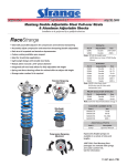
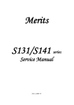
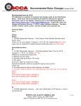
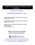
Page 1 of 8 Jul 9, 2013 Installation to be performed by a qualified technician. Front Struts • 11 Performance Settings • Wide dampening range • Ideal for street/strip applications • Steel construction • Easily accessible external knob for adjusting extension dampening • Struts are compatible with S6001 coil-over kit (except 2005 & up) • Fine-tune suspension geometry with Strange Caster Camber Kits (see pg. 3) Part # Year S6001EM 87-93 S6005LM 94-2004 S6009LM 05-2010 S6011LM 11-present Note: S6001EM fits only V8 models rear shocks Part # Year S6000EM 79-93 S6004LM 94-2004 S6008LM 2005 + Note: S6004LM does not fit Cobra with independent rear Caster camber kits SOFTER FIRMER IMPORTANT NOTES • Strange Coil-over kits and caster camber kits must be used in conjunction with one another • Reuse factory compression bumper with all kits • Top strut mount nuts are only provided with the purchase of caster camber kits • Strange caster camber plates are necessary for adjusting suspension alignment if using springs that alter the vehicle’s ride height • A wheel alignment is required after the installation of these components See alignment notes on page 7 • S6001 Coil-over kit sleeve inside diameter is 2.220 • Struts can be stroked by hand to begin proper circulation of the oil After initial strokes the shock may feel firmer DETAIL A SCALE 1 : 1 EXTENSION ADJUSTMENT Part # Year S6002CC79 79-89 S6002CC90 90-93 S6002CC94 94-2004 Note: A coil-over kit and caster camber kit is not available for 2005 + single adjustable struts Additional Parts Part # Description S6001 Coil-over kit S1413 Spanner Wrench Note: Hypercoil & Knight springs are available in a variety of rates and lengths Front Dampening Adjustment Application Knob Position Drag Race 2 or 3 Street 4 or 5 Road Race 7 or 8 • Knob is located at the bottom of the strut/shock Rear Dampening Adjustment • All struts/shocks are shipped at the softest setting or position 1 Application Knob Position • 11 Performance settings (wide range) Drag Race 5 • Full counter-clockwise is position 1 Street 4 or 5 • Full clockwise is position 11 Road Race 7 or 8 • Each position is 1/8 of a turn • Adjusting the extension dampening slightly affects compression • Compression dampening can not be adjusted independently • 3/4” 12-point socket can be used to turn the adjustment knob • Strange Engineering struts and shocks are designed for a variety of unique vehicles and drivers The dampening adjustments listed are starting points to begin fine tuning • The extension adjustment information above applies to both struts and shocks 847-663-1701 A K K AN N A BL BL BL K AN Page 3 of 8 Jul 9, 2013 Caster Camber Kits Stroke Lengths • Teflon lined bearing • Tig welded construction • Stainless steel bushings/spacers • Durable & clean zinc plating finish • Steel plates A Compressed Length B Extended Length + FRONT OF VEHICLE CASTER S6002CC79 - + CAMBER S6002CC90 B B A A - S6002CC94 Front Struts Part # S6001EM S6005LM S6009LM S6011LM A 13.0” 14.4” 15.8” 15.8” B 19.3” 20.7” 22.2” 22.2” Rear Shocks Part # A S6000EM 12.5” S6004LM 14.25” S6008LM 13” B 20.0” 20.25” 20” S6009LM S6011LM 3.5”3.5” 2.0”2.0” ! The teflon lined bearings do NOT need to be lubricated N.V. ADDITIONAL NOTES A S6001EM strut and S6000EM shock can be used on 94-2004 applications if the ride height has been lowered. Referring to the stroke lengths listed, early struts and shocks have lower compression and extension lengths however, total stroke remains about the same. Note: 2005-10 & 2011+ have different rod shoulder to rod end lengths as shown Page 4 of 8 Jul 9, 2013 S6009LM & S6011LM Strut with Factory Strut Mount S6001EM & S6005LM Strut with Factory Strut Mount M14-2mm Lock nut 50 ft-lbs Factory top plate Notch to face outboard Factory M16-2mm nut 50 ft-lbs Factory strut mount 05-2010 2011+ Factory strut dust sleeve Factory dust boot Factory compression bumper Notes: Reuse or replace top mount nuts Reuse all factory components shown Factory spring rubber insulator Notes: S6009LM & S6011LM install identically Ensure both spring ends seat properly against the mount stops. Page 5 of 8 Jul 9, 2013 S6001EM with S6002CC79 & S6002CC90 S6001 COIL-OVER KIT (sold per side) ITEM# PART# QTY 1 2 3 4 5 6 7 S6001A S6001C S6001B S6001D S4000N S4000M S6001E 1 1 1 1 1 2 1 S6002CC79 & S6002CC90 Caster Camber Kit ITEM# PART# QTY 8 9 10 11 12 13 14 15 16 17 18 ----------S2041H 2 2 6 2 2 6 6 4 4 2 2 PART# QTY 19 20 21 22 23 24 25 ------S2041H 2 2 2 4 6 2 2 17 DESCRIPTION Stud Retainer Bracket 14mm ID Flanged Bushing Caster/Camber Plate 3/8” Washer 3/8-”16 Serrated Flange Locknut 3/8” Spacer M16 x 2mm Nylon Locknut Caster/camber plate (item #12) is different for S6002CC79 & S6002CC90 kits. However, both are installed identically. Refer to pg. 3 to identify caster camber plate differences. 16 23 35 ft-lbs 15 22 40 ft-lbs 14 40 ft-lbs 24 25 40 ft-lbs 21 13 12 11 20 10 DESCRIPTION 16mm ID flanged bushing Stud Retainer Bracket 1/4” Bearing Retainer Spacer Bearing Retainer Bracket Caster/Camber Plate 7/16” Washer 7/16”-20 Flanged Nut 3/8” Washer 3/8”-24 Screw 3/8” Spacer M16 x 2mm Nylon Locknut S6002CC94 Caster Camber Kit ITEM# 18 40 ft-lbs DESCRIPTION Coil-Over Tube Ø2.220 I.D. Spring Seat Jam Nut Spring Seat Nut Top Spring Seat Thrust Bearing Thrust Bearing Washer Thrust Bearing Cover S6005LM with S6002CC94 19 5 9 7 4 8 6 6 FACTORY COMPRESSION BUMPER 7 5 VINYL COVER 4 FACTORY COMPRESSION BUMPER VINYL COVER 3 2 3 2 1 1 Page 6 of 8 Jul 9, 2013 The following instructions are guidelines for installing caster camber kits and coil-over kits Refer to the diagram on page 4 if using factory strut mount Note: 1994-04 applications may have the factory top alignment plate or mount riveted to the strut tower. The rivets will need to be removed with a drill for installation of caster camber kits. Installation: Steps 1-8 can be completed with the strut off the vehicle and pertains to all caster camber kits 1. Raise and support front of vehicle on a level surface using suitable equipment. 2. Consult the factory service manual to remove the factory strut. 3. Install the coil-over tube (1) by removing the vinyl cover from the strut and sliding the tube over the strut with the notch facing outboard to clear the strut mounting brackets. Reinstall the vinyl cover. 4. Reuse factory compression bumper. 5. Install the spring jam nut (2) followed by the spring seat nut (3) and spring. 6. Slide the top spring seat (4) over the strut piston rod . 7. Slide the thrust bearing assembly (5,6) over the piston rod followed by the thrust bearing cover (7). 8. Slide the stepped bushing (8/20) over the piston rod. Ensure smaller diameter faces up. Steps 9-12 pertain to S6002CC79 and S6002CC90 kits 9. Place the bearing retainer bracket (11) under the caster/camber plate (12) and secure with the 3/8” screws and washers (15,16). Do not torque the screw. 10. Install the stud retainer bracket (9) on the underside of the strut tower. 11. Slide the 1/4” spacers (10) through the studs and against the top of the strut tower. 12. Slide the caster/camber plate and bearing retainer bracket assembly (11, 12) through the studs and against the spacers. Secure the assembly to the shock tower using the 7/16” nut and washers (13,14). Do not torque the nuts yet. Steps 13-14 pertains to S6002CC94 Kkits 13. Install the stud retainer bracket (19) on the underside of the strut tower. 14. Slide the caster/camber plate (21) through the studs and against the shock tower. Secure the assembly to the shock tower using the 3/8” nut and washers (22,23). Do not torque the nuts yet. The following steps pertain to all kits 15. Install the strut assembly by first installing the lower factory nuts and bolts. Then raise the lower control arm with a jack while aligning the strut shaft with the bearing in the caster/camber plate. Ensure the stepped bushings (8/20) slide into the bearing. 16. Slide the 3/8” thick spacer (17/24) over the strut piston rod and install the strut locknut (18/25). Torque the locknut (1) to 40 ft-lbs. Do not use an impact wrench. Damage to the strut internal components will result. Use a 7/16” wrench on the end of the piston rod to keep it from spinning. 17. A wheel alignment must then be performed to achieve the desired caster, camber, and toe in specifications. Once complete, ensure the final torque specification. Page 7 of 8 Jul 9, 2013 WHEEL ALIGNMENT NOTES A wheel alignment is required after the installation of these components. Alignments are possible to perform at home with proper tools, setup and careful measurements. Generally, the vehicle is set to stock alignment settings and adjustments are made accordingly to driver feedback. If the alignment is performed at a professional shop and any future adjustments to either ride height, camber, caster or toe are made note that these adjustments will effect other alignment settings and therefore it is recommended to get the vehicle re-aligned. Inspect tire wear often to ensure proper alignment. It is suggested to keep records of alignment settings for reference when making future adjustments. The bottom of this page can be used to do so. RIDE HEIGHT ADJUSTMENT • Rotate the spring seat nut to the desired height • Lock the spring seat in position with the jam nut SPRING RATE & SUSPENSION NOTES Spring rates depend drastically on the particular vehicle setup. Below are some general guidelines to follow when choosing a spring rate. Typically, 14” long springs are used with Strange Engineering struts and caster/camber kits. For drag race applications with rear wheel drive soft spring rates are used in the front suspension to encourage weight transfer. A softer spring rate can be compressed more by the constant weight of the vehicle than a stiff spring at identical length. Therefore, a soft spring will have more kinetic energy stored for weight transfer. If the weight transfer is excessive the rear tire sidewall may suffer drastic deformation and unload abruptly to result in tire shake. The front extension dampening adjustment can be increased to prevent this. If there is no weight transfer occurring the front extension dampening adjustment can be decreased or a softer spring rate can be used. For the vehicle to take full advantage of weight transfer a stiff rear spring will resist compression and maintain traction. However, a spring rate which is too stiff and does not compress will transfer the weight to the tire sidewall which will unload quickly and cause uncontrollable driving conditions. The end goal with all combinations of front and rear shock settings along with spring rates is to be able to plant the tires for maximum grip by increasing the footprint. However, increasing the footprint decreases the total diameter of the tire therefore, traveling a shorter distance in a single rotation. Also note that a taller and longer tire foot print is preferable for forward traction compared to merely a wide foot print. Track experience and careful documentation will result in the best combinations of strut and shock adjustment and springs. DF PF Camber Camber Front Spring Rate Toe Toe Front Spring Length Caster Caster DR PR Rear Spring Rate Rear Spring Length Camber Camber Ride Height Toe Toe Notes: Caster Caster Page 8 of 8 Strut & Shock Dyno Graphs: Jul 9, 2013 The following graphs show the average resistance of the shock extension (red) and compression (blue) forces as the shock velocity increases. Note that the adjustment control knob adjusts extension and slightly affects compression. Compression can not be adjusted independently of extension with single adjustable struts and shocks.