1
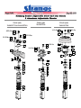
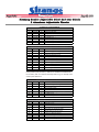
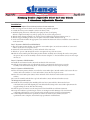
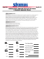
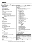
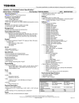
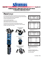
Page 1 of 9 Aug 27, 2013 Installation to be performed by a qualified technician. • Externally accessible adjusters for compression and extension dampening • Accurately adjust compression and extension dampening (double adjustable) • Each strut is inspected and tested on dynamometer • Custom valving available upon request • Ideal for street/strip applications • Light-weight design with durable steel body • Robust 22mm rod and 1.375” piston diameter • Integrated coil-over body allows for fully adjustable ride height • Spring seat thrust bearings allow for minimal effort to adjust ride height • Strange caster camber kit is required Extension Dampening Adjustment SOFTER FIRMER Struts B Part # Adjustability Year S2041 Double 1987-2004 S2043 Double 2005 + Notes: 87-93 V8 models only S2043 does not clear GT500 Shelby Wheels shocks Part # Adjustability Year S5045 Double 64-73 S5046 Double 64-73 S5044 Double 79-93 S5050 Double 94-2004 S5042 Double 2005 + S5242 Single 2005 + Note: S5045 is the front shock 94-04 does not fit Cobra with independent rear Rear Coilover shocks Part # Adjustability Year S5048 Double 79-04 S5248 Single 79-04 Note: Coil-over shock instructions see pg. 9 Caster camber kits Ride Height Adjustment Part # S6002CC79 S6002CC90 S6002CC94 S6002CC05 Year 79-89 90-93 94-2004 2005 + Additional Parts Part # Description S1413 Spanner Wrench Compression Dampening Adjustment FIRMER SOFTER Hypercoil & Knight springs are available in a variety of rates and lengths 1987-2011 Ford Mustang Strut packages are available with springs and caster camber kits. Call for information F F 847-663-1701 K K K AN N N A BL A BL BL Page 2 of 9 Aug 27, 2013 Strange Caster Camber Kits • Teflon lined bearing • Tig welded construction • Stainless steel bushings/spacers • Durable & clean zinc plating finish • Steel plates A Compressed Length B Extended Length FRONT OF VEHICLE CASTER S6002CC79 Stroke Lengths + + CAMBER S6002CC90 B B A A S6002CC94 Shocks Struts S6002CC05 Year 87-2004 05 + A 13.1” 12.9” B 19.1” 20.1” Lengths listed are for Strange struts/shocks ! Year 64-73 (front) 64-73 79-93 94-2004 05 + A 8.50 11.7 12.9” 14.3” 12.9” B 12.9 17.2 20.1” 19.7” 20.1” 94+ applications will have 1” shorter extended and compressed lengths allowing for a lower ride height while maintaining OEM stroke length. 87-93 maintain OEM extended and compressed lengths. N.V. The teflon lined bearings do NOT need to be lubricated Page 3 of 9 Aug 27, 2013 NOTES The front suspension of a drag race vehicle is tuned accordingly to rear tire reaction. When at the track, the sidewall of the rear tire and clearance between tire and fender should be observed. A rapid weight transfer that generally causes the vehicle rear to “bounce” will be evident by a sudden decrease in the tire and fender clearance as well as a sudden decrease in tire sidewall height. A slow weight transfer will generally cause tire spin and will be evident by the tire sidewall and fender to wheel clearance not decreasing significantly. Refer to notes on pg. 7 for further information. Understanding these basic principles will promote a better response to tune vehicle dynamics and suspension for superior car performance. STRUT EXTENSION ADJUSTMENT SHOCK EXTENSION ADJUSTMENT • 3/8 and 7/16 wrenches are used to adjust extension • Hex is located at the top of the piston rod • Full clockwise is the softest position • Full counter-clockwise is the firmest position • 3-1/8 total turns of adjustment • 10 settings • Full clockwise is the firmest position • Full counter-clockwise is the softest position • Shipped at softest settings STRUT COMPRESSION ADJUSTMENT SHOCK COMPRESSION ADJUSTMENT • Hex is located at the bottom of strut body • Full clockwise is the firmest position • Full counter-clockwise is the softest position • 12 clicks • 13 total settings • Compression is adjustable only on double adjustable shocks • 9 compression settings • Full clockwise is the firmest position • Full counter-clockwise is the softest position • “Clicks” 1/8 every turn for fine adjustment Front Extension Dampening Application Adjustment Drag Race 0.5-1.0 turns Street 1.25-1.5 turns Road Race 2.0-2.5 turns Front Compression Dampening Application Adjustment Drag Race 4 or 5 Street 4 or 5 Road Race 7 or 8 Rear Extension Dampening Application Knob Position Drag Race 5 Street 4 or 5 Road Race 7 or 8 Rear Compression Dampening Application Adjustment Drag Race 2 or 3 Street 4 or 5 Road Race 7 or 8 B Extension Dampening Adjustment FIRMER SOFTER B Compression Dampening Adjustment FIRMER DETAIL A SCALE 1 : 2 SOFTER Strange Engineering struts and shocks are designed for a variety of unique vehicles and drivers The dampening adjustments listed are starting points to begin fine tuning Page 4 of 9 Aug 27, 2013 S2041 with S6002CC94 S2041 with S6002CC79 & S6002CC90 S2043 with S6002CC05 17 35 ft-lbs 14 13 34 40 ft-lbs 35 ft-lbs 32 50 ft-lbs 18 33 28 16 22 ft-lbs 15 12 25 50 ft-lbs 24 11 35 ft-lbs 23 22 10 21 31 30 28 27 28 26 9 20 8 6 7 5 4 3 2 1 19 6 7 5 27 7 6 5 4 3 4 3 2 1 2 1 29 28 Page 5 of 9 Aug 27, 2013 COMMON COMPONENTS ITEM# PART# QTY 1 2 3 4 5 6 7 S6001C S6001B S3600W S6001D S4000N S4000M S6001E 1 1 1 1 1 2 1 DESCRIPTION Spring Seat Jam Nut Spring Seat Nut Compression Bumper Top Spring Seat Thrust Bearing Thrust Bearing Washer Thrust Bearing Cover S6002CC79 & S6002CC90 Caster Camber Kit ITEM# PART# QTY 8 9 10 11 12 13 14 15 16 17 18 ----------S2041H 2 2 6 2 2 6 6 4 4 2 2 DESCRIPTION 16mm ID flanged bushing Stud Retainer Bracket 1/4” Bearing Retainer Spacer Bearing Retainer Bracket Caster/Camber Plate S6002CC979/S6002CC90 7/16” Washer 7/16”-20 Flanged Nut 3/8” Washer 3/8”-24 Screw 3/8” Thick Spacer M16 x 2mm Nylon Locknut Caster/camber plate (item #12) is different for S6002CC79 & S6002CC90 kits. However, both are installed identically. Refer to pg. 2 to identify caster camber plate differences. S6002CC94 Caster Camber Kit ITEM# PART# QTY 19 20 21 22 23 24 25 ------S2041H 2 2 2 ITEM# PART# QTY DESCRIPTION 26 27 28 29 30 31 32 33 34 ---- 2 16 32 ----- 2 8 8 2 2 14mm ID spacer 3/8”-16 locknut 3/8” ID x 1/16” thick flat washer Caster plate w/ spherical bearing Camber plate w/ press in studs 3/8” ID x 1/8” thick flat washer 3/8”-16 x 1-1/4” long HHCS 14mm ID flanged bushing M14 x 2mm locknut (factory thread) 6 6 2 2 DESCRIPTION 14mm ID Flanged Bushing Stud Retainer Bracket Caster/Camber Plate 3/8” Washer 3/8”-16 Serrated Flange Hex Locknut 3/8” Thick Spacer M16 x 2mm Nylon Locknut S6002CC05 Caster Camber Kit --- 2 Page 6 of 9 Aug 27, 2013 Installation: Steps 1-6 can be completed off the vehicle and pertains to all caster camber kits 1. Raise and support front of vehicle on a level surface using suitable equipment. 2. Consult the factory service manual to remove the factory strut. . 3. Install the spring lock nut (1) followed by the spring seat nut (2) and spring. Slide the compression bumper (3) and top spring seat (4) over the strut piston rod . 4. Slide the thrust bearing assembly (5,6) over the piston rod followed by the thrust bearing cover (7). 5. Slide the stepped bushing (8/19/26) over the piston rod. Ensure smaller diameter faces up. 6. Set the strut aside and follow the appropriate caster camber kit instructions below to install the caster camber kit on the strut tower. Steps 7-10 pertain to S6002CC79 and S6002CC90 kit 7. Place the bearing retainer bracket (11) under the caster/camber plate (12) and secure with the 3/8” screws and washers (15,16). Do not torque the screws. 8. Position the stud retainer bracket (9) on the underside of the strut tower. 9. Slide the 1/4” spacers (10) through the studs to seat against the top of the strut tower. 10. Slide the caster/camber plate and bearing retainer bracket assembly (11,12) through the studs to seat against the spacers (10). Secure the assembly to the shock tower using the 7/16” nut and washers (14,13). Do not torque the nuts yet. Steps 11-12 pertains to S6002CC94 Kkits 11. Install the stud retainer bracket (20) on the underside of the strut tower. 12. Slide the caster/camber plate (21) through the studs to seat against the shock tower. Secure the assembly to the shock tower using the 3/8” nut and washers (23,22). Do not torque the nuts yet. Steps 13-15 pertains to S6002CC05 Kkits 13. Place the bearing retainer bracket (29) under the caster/camber plate (30) with washers (28) between the two surfaces and secure with the 3/8” screws and washers (27,28). Do not torque the screw. 14. Place the caster/camber plate (30,29) on the underside of the shock tower with washers (31) between the surfaces. 15. Secure the assembly with the three top bolts and washers (28,32) and nut and washers (27,28). The following steps pertain to all kits 16. Install the strut assembly by first installing the lower factory nuts and bolts. Then raise the lower control arm with a jack while aligning the strut shaft with the bearing in the caster/camber plate. Ensure the stepped bushings (8/19/26) slide into the bearing. 17. Slide the spacer (17/24/33) over the strut piston rod and install the strut locknut (18/25/34). 18. Torque the locknuts to specified torque. Do not use an impact wrench. Damage to the strut internal components will result. Use a 7/16” wrench on the end of the piston rod to keep it from spinning. 19. A wheel alignment must then be performed to achieve the desired caster, camber, and toe in specifications. Once complete, ensure final torque specification on all hardware. Page 7 of 9 Aug 27, 2013 WHEEL ALIGNMENT NOTES A wheel alignment is required after the installation of these components. Alignments are possible to perform at home with proper tools, setup and careful measurements. Generally, the vehicle is set to stock alignment settings and adjustments are made accordingly to driver feedback. If the alignment is performed at a professional shop and any future adjustments to either ride height, camber, caster or toe are made note that these adjustments will effect other alignment settings and therefore it is recommended to get the vehicle re-aligned. Inspect tire wear often to ensure proper alignment. It is suggested to keep records of alignment settings for reference when making future adjustments. The bottom of this page can be used to do so. RIDE HEIGHT ADJUSTMENT • Rotate the spring seat nut to the desired height • Lock the spring seat in position with the jam nut SPRING RATE & SUSPENSION NOTES Spring rates depend drastically on the particular vehicle setup. Below are some general guidelines to follow when choosing a spring rate. Typically, 14” long springs are used with Strange Engineering struts and caster/camber kits. For drag race applications with rear wheel drive soft spring rates are used in the front suspension to encourage weight transfer. A softer spring rate can be compressed more by the constant weight of the vehicle than a stiff spring at identical length. Therefore, a soft spring will have more kinetic energy stored for weight transfer. If the weight transfer is excessive the tire sidewall may suffer drastic deformation and unload abruptly to result in tire shake. The front extension dampening adjustment can be increased to prevent this. If there is no weight transfer occurring the front extension dampening adjustment can be decreased or a softer spring rate can be used. For the vehicle to take full advantage of weight transfer a stiff rear spring will resist compression and maintain traction. However, a spring rate which is too stiff and does not compress will transfer the weight to the tire sidewall which will eventually unload and cause uncontrollable driving conditions. The end goal with all combinations of front and rear shock settings along with spring rates is to be able to plant the tires for maximum grip by increasing the footprint. However, increasing the footprint decreases the total diameter of the tire therefore, traveling a shorter distance in a single rotation. Also note that a taller and longer tire foot print is preferable compared to merely a wide foot print. Track experience and careful documentation will result in the best combinations of strut and shock adjustment and springs. DF PF Camber Camber Front Spring Rate Toe Toe Front Spring Length Caster Caster DR PR Rear Spring Rate Rear Spring Length Camber Camber Ride Height Toe Toe Notes: Caster Caster Page 8 of 9 Aug 27, 2013 Strut & Shock Dyno Graphs: The following graphs show the average resistance of the shock extension and compression forces as velocity increases. Mustang Steel Double Adjustable Coil-over Strut Force vs. Velocity 284.9 250 200 Compression Adjustment Range 150 100 Force (lbs) 50 0 -50 -100 Extension Adjustment Range -150 -200 Minimum Adjustment Maximum Adjustment -250 -300 -328.7 0.00 0.5 1.0 1.5 2.0 2.5 3.0 3.5 4.0 4.5 5.0 5.5 Velocity (in/sec) 6.04 Mustang Aluminum Double Adjustable Shocks Force vs. Velocity 350 300 250 Compression Adjustment Range 200 150 Force (lbs) 100 50 0 -50 -100 -150 -200 -250 Extension Adjustment Range Minimum Adjustment Maximum Adjustment -300 -350 -400 -450 -500 -529.4 0.00 0.5 1.0 1.5 2.0 2.5 3.0 3.5 Velocity (in/sec) 4.0 4.5 5.0 5.5 6.03 Page 9 of 9 Aug 27, 2013 Installation: S5048 & S5248 Coilover Shocks 1. Safely raise and support the vehicle off the ground. Remove the factory shock. 2. Attach the shock mount adapter (12) to the factory shock mount location using the one of the 1/2” screws (8). Ensure the mount is perpendicular to housing. 3. Use the upper hole as a template and drill a 1/2” hole through the factory shock mount bracket on the rear end housing. 4. To install the spring onto the shock, screw the jam nut (7) and spring seat nut (6) all the way down to the bottom. Then with the top spring seat (5) removed from the shock, slide the spring over the shock. Using a suitable spring compressor, compress the spring just enough to be able to slide the top spring seat around the piston rod. Release tension on the spring compressor while aligning the spring with the top spring seat and the spring seat adapter. 6. Slide a cushion washer (2) and rubber (3) on the top shock stud. 7. Slide the shock up from the bottom of the car extending the top stud mount through the hole in the body. Slide a rubber cushion (3) and cushion washer (2) over the top stud mount and then install the 3/8”-24 lock nut (1). On the underside of the car, hold the top stud mount across the machined flats using a 3/4” open end wrench. Tighten the 3/8” lock nut until the rubber cushion begins to expand slightly around the cushion washer. After installation, the carpet and interior can be reinstalled. 8. Raise the rear end housing with the jack and position the shock in the lower shock mount and secure with the 1/2” screw and nut (13, 14). Note: For double adjustable shocks position the plastic extension knob towards the rear end housing tube. 9. Single adjustable shocks can be positioned with the extension knob facing either direction. Torque all the hardware to the spec listed in the diagram below. KIT CONTENTS ITEM# PART# QTY 1 2 3 4 5 6 7 8 9 10 11 12 13 14 S5001Y S5001X S5001W S5001M S510V S510S S510T B4160B S5001KB A1026AM H1135C H1114C S5001KB S5001KA 1 2 2 1 1 1 1 2 4 1 1 1 4 2 DESCRIPTION 3/8"-24 Lock nut Cushion washer Shock cushion Spring Seat Adapter Top Spring Seat Spring Seat Nut Spring Seat Jam Nut 1/2"-20 x 1-1/2" HHCS 1/2" washer 1/2"-20 x 2-1/4" HHCS 1/2"-20 Flexlock nut Lower shock mount 1/2" washer 1/2"-20 Lock nut 1 35 ft-lbs 2 3 3 2 4 5 14 75 ft-lbs 13 9 10 8 14 6 13 7 75 ft-lbs 11 12 9 8