1
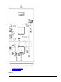
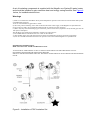
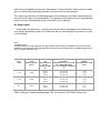
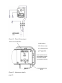
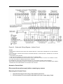
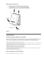
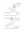
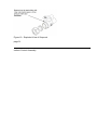
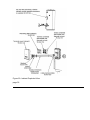
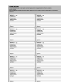
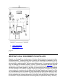
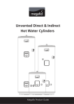
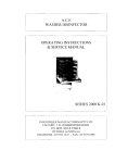
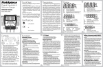
Unvented Indirect SystemFit Hot Water Cylinders Megaflo Product Guide page 1 Contents Product Specification Installation and Commissioning Instructions Maintenance and Servicing User Guide page 2 PRODUCT SPECIFICATIONS Introduction Checklist General Requirements Water Supply Power Supply The Environment Specification and Dimensions page 3 THE BENCHMARKTM SCHEME BenchmarkTM places responsibilities on both manufacturers and installers. The purpose is to ensure that customers are provided with the correct equipment for their needs, that it is installed,commissioned and serviced in accordance with the manufacturer's instruct ions by competent persons and that it meets the requirements of the appropriate Buildi ng Regulations. The BenchmarkTMChecklist can be used to demonstrate compliance wi th Building Regulations and should be provided to the customer for future reference. Ins tallers are required to carry out installation, commissioning andservicing work in accorda nce with the Benchmark Code of Practice which is available from the Heating and Hotw ater Industry Council who manage and promote the scheme. Visit www.centralheating.c o.uk for more information. IMPORTANT NOTE TO USER: PLEASE REFER TO THE USER GUIDE SECTION FO R IMPORTANT INFORMATION WITH RESPECT TO THE BENCHMARK SCHEME Introduction Congratulations on your purchase of a Megaflo eco SystemFit unvented water heater. T he Megaflo eco SystemFit is a factory preplumbed and wired Megaflo eco unvented water heater. The Megaflo ecoSystemFit is m anufactured in the UK from top quality materials and meets all the latest relevant safety and constructional standards. The high grade Duplex stainless steel cylinder offers exce ptionalstrength and corrosion resistance which is backed by a lifetime guarantee (see te rms and conditions). Its performance, control system and insulation levels exceed the la test requirements of BuildingRegulation Part L. The Megaflo eco SystemFit unvented water heater can be fed directly from the cold wat er mains supply to the property without the need for separate feed cisterns or vent pipes . It is supplied fitted with allits necessary inlet and safety controls for compliance with Bu ilding Regulations. Also fitted are a primary circulating pump, automatic bypass valve, a flow balancing valve, 2 x 2 port motorised valves,automatic air vent, primary filling loop and pressure gauge, a cylinder thermostat, thermal cutout and wiring centre. The pump, motorised valves and thermal controls are supplied pr ewired. A heating anddomestic hot water programmer, room temperature sensor, primary expansion vessel and primary expansion relief valve are supplied loose for installation at a convenient position within the property. Anelectric immersion heater is also fitted to enable the unit to be heated should the boiler be turned off. The Megaflo eco SystemFit primary circuit can be connected to a variety of gas or oil fir ed boiler types, either open vented or sealed system. It is not recommended for use wit h "system" boilers as thesealready incorporate their own circulating pump and controls. The Megaflo eco SystemFit requires no separate expansion vessel for the domestic hot water as any expanded water is accommodated within an internal air volume. NOTE: If using a sealed heating system, adequate provision for expansion within the primary circuit MUST be provided by fitting the primary circuit expansion ves sel supplied. Primarycircuit expansion cannot be accommodated within the Mega flo eco SystemFit. Ensure the primary circuit expansion relief valve (supplied) is fi tted to the primary circuit. The safety valves fitted to the Megaflo eco SystemFit protect the water heater onl y. Failure to provide adequate primary system pressure relief when using a seale d heating system willinvalidate the boiler manufacturer's warranty. Consult the bo iler manufacturer's installation instructions for further advice. System type boilers will usually have the primary circulation pump and primary e xpansion vessel fitted within the boiler itself, for this reason these type of boilers are not recommendedfor use with the Megaflo eco Systemfit as these component s are also supplied with the Megaflo eco Systemfit unit. page 4 Component Check List Before commencing installation, check that all components for your Megaflo eco Syste mFit unit are contained in the package. The following components are supplied: Factory Fitted: Immersion heater(s) and thermal controls 8 Bar pressure relief valve (incorporating a check valve) (Figure 5) Temperature / pressure relief valve (set at 90°C / 1 MPa (10bar) Tundish Indirect thermostat and thermal cut-out T&P relief valve insulation set Drain valve Wiring centre 2 x 2-Port motorised valve Primary circulation pump Lock-shield flow balancing valve Differential bypass valve Filling loop, straight Automatic air vent Primary circuit pressure gauge Drain valve (with quarter turn lever) Supplied loose: 3 Bar pressure reducing valve (incorporating strainer) (Figure 3) Stop cock (Figure 4) CD/DHW programmer and room temperature sensor Primary circuit expansion vessel (including wall mounting bracket) Lifting handle Fixing template Primary expansion relief valve page 5 General Requirements Important: Please read and understand this product guide before installing the Megaflo eco SystemFit water heater. Incorrect installation may invalidate the guarantee. This ap pliance is not intended foruse by persons (including children) with reduced physical, sen sory or mental capabilities, or lack of knowledge and experience, unless they have been given supervision or instruction concerning he use ofthe appliance by a person respons ible for their safety. The Megaflo eco SystemFit must be Installed (Section 2), Commissi oned (Section 2) and Maintained (Section 3) by a competent installer inaccordance with Building Regulation G3 (England and Wales), Technical Standard P3 (Scotland) or Buil ding Reulation P5 (Northern Ireland) and the Water Fitting Regulations (England and W ales) orWater Byelaws (Scotland) Following installation and commissioning, the operati on of the heater should be explained to the user (Section 4) and this product guide left with them for future reference. Storage and Handling Please take care when handling a packaged Megaflo eco SystemFit. The unit is heavy and must only be moved manually within safe working practices. If the unit is to be store d before installation, it mustbe placed on a secure, level surface and in a dry, frost free environment. Siting the Megaflo eco SystemFit (See Figure 1 below) The Megaflo eco SystemFit unit must be vertically floor mounted. It can be placed anyw here convenient provided the discharge pipe(s) from its safety valves can be correctly in stalled. Areas that aresubject to freezing must be avoided. Ensure that the floor is of suf ficient strength to support the "full" weight of the unit (refer to Table 3 for unit weights). P ipe runs should be kept as short as possible formaximum economy. Access to associate d controls, immersion heaters and indirect controls should be possible for servicing and maintenance of the system. Please do not install valves or pipework (except discharge pipe) within 50mm (2") of the T&P relief valve to allow your insulation set to be fitted. The insulation set is important t o ensure heat and energyconservation. See section 2 for more information. To aid installation, the Megaflo eco SystemFit is provided with lifting points located in th e base moulding and a lifting handle. The lifting handle should be fully threaded onto the outlet boss before use.Once the Megaflo eco SystemFit is suitably positioned the lifting handle should be removed to allow connection of the outlet pipework. The weight of the units are noted on Table 3. If you choose to install the Megaflo eco SystemFit in the highest point in the property (e. g. loft space), it is advisable to install an additional automatic air vent (AAV, not supplied ) (available as a spare,part number 95 605 050) above the pump to enable air to be remo ved from the system. The addition of the AAV is not required if siting the cylinder in a lo wer position. Figure 1 - Typical Schematic Installation Details page 6 Outlet / Terminal Fittings (Taps, Etc.) The Megaflo eco SystemFit can be used in conjunction with most types of terminal fittin gs. It is advantageous in many mixer showers to have balanced hot and cold water sup plies, in these instances thebalanced cold water supply should be teed off the supply to the Megaflo eco SystemFit immediately after the 3 bar pressure reducing valve (See Fig ure 6). Branches to cold drinking outlets should betaken before the valve. Outlets situated higher than the Megaflo eco SystemFit unit will give outlet pressures lo wer than that at the heater, a 10m height difference will result in a 0.1 MPa (1 bar) press ure reduction at the outletfitting. NOTE: Accessories should have a rated operating pressure of at least 0.8 MPa (8 bar). Limitations The Megaflo eco SystemFit unvented water heater should not be used in any of the follo wing instances: Solid fuel boilers or any other boiler in which the energy input is not under effectiv e thermostatic control unless additional and appropriate safety measures are inst alled. Gravity circulation primaries. Steam heating plant unless additional and appropriate safety devices are installe d. Ascending spray type bidets or any other Class 5 back syphonage risk requiring t hat a Type AA, AB, AD or AG air gap be employed. Water supplies that have either inadequate pressure or where the supply may be intermittent. Situations where it is not possible to safely pipe away any discharge from the saf ety valves. Areas where the water consistently contains a high proportion of solids, e.g. susp ended matter that could block the strainer, unless adequate filtration can be ensu red. The installation must be carried out in accordance with the relevant requirements of: The appropriate Building Regulations: Either The Building Regulations (England), The Building Regulations (Scotland) or Building Regulations (Northern Ireland). The Water Fittings Regulations (England and Wales) or Water Byelaws (Scotland ). Water Supply Bear in mind that the mains water supply to the property will be supplying both the hot a nd cold water requirements simultaneously. It is recommended that the maximum water demand be assessed andthe water supply checked to ensure this demand can be met. NOTE: A high mains water pressure will not always guarantee high flow rates. Wherever possible the main supply pipe should be in 22mm. The minimum mains water supply requirements should be 0.15 MPa (1.5 bar) working pressure and 20 litres per m inute flowrate. At these values outlet flowrates may be poor if several outlets are used simultaneously, the higher the available pressure and flowrate the better the system performance will be . The Megaflo eco SystemFit has an operating pressure of 3 bar which is controlled by th e 3 bar pressure reducing valve. The 3 Bar pressure reducing valve can be connected t o a maximum mains supplypressure of 1.6 MPa (16 bar). The water supply must be of wholesome water quality (Fluid Category 1 as defined by the Water Supply Regulations 1999). The Megaflo eco SystemFit is to be used for the storage of wholesome water (max. 250 mg/l chloride). Electrical Supply WARNING: THIS APPLIANCE MUST BE EARTHED. IT IS SUITABLE FOR A.C. SUP PLY ONLY. ELECTRICAL INSTALLATION MUST BE CARRIED OUT BY A COMPET ENT ELECTRICIAN AND BEIN ACCORDANCE WITH THE LATEST I.E.E. WIRING R EGULATIONS. ENSURE THE ELECTRICAL SUPPLY IS SWITCHED OFF BEFORE MAKING ANY C ONNECTIONS TO THE MEGAFLO ECO SYSTEMFIT The Environment This product is made from many recyclable materials, therefore at the end of its useful li fe it should be disposed of at a Local Authority Recycling Centre in order to realise the f ull environmental benefits.Insulation is by means of an approved HCFC/CFC free polyur ethane foam. page 7 Specifications and Dimensions Outline Specifications Maximum mains water supply pressure (to 3 bar pressure reducing valve) 1.6 MPa (16 bar) Operating pressure (pressure reducing valve set pressure ( non adjustable) 0.3 MPa (3 bar) Expansion relief valve set pressure 0.8 MPa (8 bar) Temperature / pressure relief valve set temp / pressure 90°C / 1MPa (10 bar) Immersion heater rating (a.c. supply only) 3kW @ 240V 50Hz 2.8kW @ 230V 50Hz Outer casing: White textured plastic coated corrosion resistant steel Water container: Duplex stainless steel. 100% pressure tested to 1.5 MPa (15 bar). Thermal insulation: CFC/HCFC free fire retardant expanded polyurethane foam with zero ozone depletion potential. It has a Global Warming Potential (GWP) of 3.1. Nominal thickness 60mm. Pipe connections: All connections accept 22mm outside diameter pipe - compression nuts and olives supplied. Thread rate is 3/4" BSP male parallel to accept standard 3/4" BSP female fittings if required. Safety features: Manually resettable thermal cut-out on heating element Manually resettable thermal cut-out for primary heating. Must be wired in conjunction with 2port motorised valve supplied Factory fitted temperature / pressure relief valve The pace of product development is such that we reserve the right to change product sp ecifications without notice. We do, however, strive to ensure that all information in this p roduct guide is accurate atthe time of publication. STANDING HEAT LOSS NOMINAL CAPACITY (LITRES) PER DAY PER YEAR (kWh/24h) (kWh/24h) 125 1.19 434.35 145 1.32 481.80 170 1.42 518.30 210 1.57 573.05 250 1.67 609.55 300 1.89 689.85 Table 1 - Standing Heat-loss SIZE TYPE DIMENSIONS (mm) INDIRECT A B C D E F 125L i 316 355 794 1102 709 N/A 145L i 316 355 895 1229 810 N/A 170L i 316 355 1020 1384 934 N/A 210L i 316 355 1095 1486 1011 * 250L i 316 355 1323 1738 1238 * 300L i 316 355 1574 2053 1526 * * A SECOND ELEMENT KIT CAN BE PURCHASED, KIT NO 95970554 Table 2 - Dimensions page 8 Figure 2 - Megaflo eco SystemFit Indirect Dimensions (Plan View) Technical Specification SIZE UNIT WEIGHT (kg) COIL SPECIFICATIONS EMPTY FULL SURFACE (SQ/M) HEAT-UP (MINS) RECOVERY (MINS) RATING (kW) 125L 43 183 0.58 23 15 18.3 145L 48 203 0.72 24 17 18.7 170L 52 234 0.79 22 16 24.3 210L 55 254 0.79 28 19 24.3 250L 61 297 0.79 34 23 23.9 300L 69 352 0.79 39 27 24.5 NOTE Coil heating performance based on a primary flow rate of 15L/min at 80°C. Temperature rise is from 15°C to 60°C. Table 3 - Technical Specification page 9 Danfoss TP9000 Programmable Thermostat with timed Domestic Hot Wa ter (DHW) control: Programmer dimensions: 135mm (W) x 88mm (H) x 32mm (D) Room temperature sensor dimensions: 60mm (W) x 45mm (H) x 21mm (D) Power supply: 220V/240V ac, 50Hz Switch action 2 x SPDT, Type 1B. Switch rating 220/240V ac, 50/60Hz, 3(1)A Power reserve: minimum 24 hours Memory back up retained for life of product Enclosure rating: IP30 Control temperature range: selectable 5 to 30°C Holiday mode with room temperature setback Timing accuracy: +/- 1 minute/month Maximum ambient temperature: 45C° Honeywell 2 Port Motorised Valves: Model No.: V4043H Voltage rating: 230V ac, 50HZ Power consumption: 6W Primary water temperature range: 5 to 88°C Maximum ambient temperature: 52°C Automatic Differential By-pass Valve: Model No.: RWC DIFF 200 005 Setting range: 0 to 0.05 MPa (0 to 0.5 bar) differential pressure Maximum primary water temperature: 110°C page 10 Primary Circulating Pump: Model No.: Grundfos UPS15-60 Working pressure: 1 MPa (10 bar) max. Voltage rating: 230V ac, 50Hz Starting capacitor: 2uF Enclosure rating: IP42 Electrical Data SPEED SPEED INPUT FULL LOAD LOCKED ROTOR SETTING R.P.M. POWER (W) CURRENT (A) CURRENT (A) III 1750 95 0.44 0.47 II 1100 65 0.30 0.31 I 750 40 0.17 0.18 Pump Curves page 11 INSTALLATION AND COMMISSIONING INSTRUCTION S General Installation Commissioning page 12 General Installation Pipe Fittings The connection points to the heating system are in 22mm o/dia copper pipe on 125 and 145 litre units. On units 170 litres and above the primary flow connection is 28mm, the fl ow connections to centralheating (CH) zones 28mm and the domestic hot water (DHW) return connection 22mm o/dia copper pipe. The use of appropriately sized COMPRESSI ON FITTINGS is recommended when connecting tothe Megaflo eco SystemFit pipes. S older fittings can be used, but extreme care must be taken to ensure the plastic coating of the unit casing is not damaged by heat. Push fit type fittings can be used forconnectio n to the copper pipes. The inlet connection to the 3 bar pressure reducing valve is 22m m compression. The Megaflo eco SystemFit outlet fitting is suitable for connection to 22 mm o/dia pipe (compression nut and olive supplied). The outlet is also threaded 3/4" BS P male parallel should threaded pipe connections be preferred. Cold Water Supply A 22mm cold water supply is recommended, however, if a 15mm (1/2") supply exists wh ich provides sufficient flow (see Section1 "Water Supply") this may be used. More flow n oise may be experiencedfrom small bore pipes due to the increased water velocity throu gh them. The 3 bar pressure reducing valve supplied with the Megaflo eco SystemFit incorporate s a full flow isolating valve (separate part, See Figure 4) which will enable the Megaflo e co SystemFit to be isolatedfrom the mains supply for maintenance or servicing. To close the valve the blue handle should be turned so that it lies at 90° to the direction of flow. To open, turn the handle so that it lies parallel to thedirection of flow. 3 Bar Pressure Reducing Valve (See Figure 3 below) The 3 bar pressure reducing valve can be connected anywhere on the cold water mains supply prior to the Megaflo eco SystemFit unit. There is no requirement to site it close t o the unit, it can be locatedat a point where the mains supply enters the premises if this is more convenient but you must install a nonreturn valve just after the reducing valve for ease of maintenance. The 3 bar pressure reducing valve can be installed as a complete onepiece unit or incorporating the stopcock (see Fig 4). The valve incorporates a factory set , nonadjustable pressure reducer / strainer.The valve can be fitted in any orientation to suit th e installation, however, ensure that the valve is installed with the direction of flow arrows (stamped on the side of the brass body) pointing towards theMegaflo eco SystemFit he ater. If a balanced pressure cold water supply is required to a thermostatic shower mixer valv e this may be teed off the supply to the Megaflo eco SystemFit immediately after the 3 b ar pressure reducing valve (See Figure 6). Figure 3 - 3 Bar Pressure Reducing Valve page 13 8 bar pressure relief valve (See Figure 5) Should a balanced pressure cold water draw off supply be required for the cold water ou tlets, this should be taken off between the 3 bar pressure reducing valve and 8 bar pres sure relief valve (see Figure 6). Branches to drinking water outlets should be taken before the valve to avoid the possibility of warm expanded water being drawn fro m the tap. 3 Bar Pressure Reducing Valve with Stopcock Stopcock is grouped with the 3 Bar pressure Reducing valve. Make sure the flow is corr ect to the markings on the valve. Figure 4 - 3 Bar Pressure Reducing Valve with Stopcock 8 Bar Pressure Relief Valve Figure 5 - 8 Bar Pressure Relief Valve page 14 Schematic installation diagram using 3 Bar Pressure Reducing Valve in conjuncti on with 8 Bar Pressure Relief Valve Figure 6 Schematic installation diagram using 3 Bar Pressure Reducing Valve in conjunction wit h 8 Bar Pressure Relief Valve page 15 Drain Taps Drain taps are fitted to both the primary system pipework and the cold water inlet to facil itate draining the unit or indirect heating heating circuit for maintenance purposes. It is r ecommended that the outletpoint of the drain pipe work be at least 1 metre below the le vel of the heater (this can be achieved by attaching a hose pipe to the drain tap outlet s pigot). Outlet Pipework Ideally the pipework from the Megaflo eco SystemFit to the outlet fittings should be in 22 mm pipe with short runs of 15mm pipe to showers and basin taps. Small bore pipe can also be used to suit sometaps, but runs should be of minimum length. Pipe sizes may v ary due to system design. Secondary Circulation If a secondary circulation system is required it is recommended that it be connected to t he Megaflo eco SystemFit as shown in Figure 7 below. The secondary return pipe shoul d be in 15mm pipe andincorporate a check valve to prevent backflow. A suitable WRAS approved bronze circulation pump will be required. On large systems, due to the increas e in system water content, it may be necessary tofit additional expansion volume to the system by fitting an external expansion vessel to the secondary circuit. This should be d one if the capacity of the secondary circuit exceeds 10 litres. Pipe Capacities (copper) 15mm o/d = 0.13 litres per metre run (10 litres = 77m) 22mm o/d = 0.38 litres per metre run (10 litres = 26m) 28mm o/d = 0.55 litres per metre run (10 litres = 18m) Secondary Circulation Connection Figure 7 - Secondary Circulation Connection page 16 T&P Relief Valve Insulation A set of insulating components is supplied with the Megaflo eco SystemFit water heater and should be installed to gain maximum heat and energy saving benefits. See Figure 8 below, for installationinstructions. Warnings i) Under no circumstances should the factory fitted temperature /pressure relief valve be removed other than by auth orised Heateam personnel. To do so will invalidate any guarantee or claim. ii) The 3 bar pressure reducing valve must be fitted to the mains water supply to the Megaflo eco SystemFit unit. iii) No control or safety valves should be tampered with or used for any other purposes. iv) Water may drip from the discharge pipe of the 8 bar pressure relief valve (expansion valve) and this pipe must be left open to atmosphere. The discharge pipe should not be blocked or used for any other purpose. v) The tundish must be installed so that it is visible to the end user. vi) The tundish, drain valve and motorised valves must be installed away from any electrical components. vii) No valve should be fitted between the 8 bar pressure relief valve and the Megaflo eco SystemFit unit. IMPORTANT INFORMATION: HOW TO INSULATE YOUR T&P RELIEF VALVE TO SAVE HEAT AND ENERGY A SET OF INSULATING PARTS FOR THE T&P RELIEF VALVE HAVE BEEN SUPPLIED WITH THIS WATER HEATER. INSTALL THE HEATER FIRST THEN FIT THE INSULATING PARTS BY FOLLOWING THE DIAGRAMS B ELOW. Figure 8 - Installation of T&P Insulation Set page 17 The following extract is taken from the latest G3 Regulations Discharge pipes from safety devices Discharge pipe D1 3 Safety devices such as temperature relief valves or combined temperature and pressure and pressure relief valves . (see paragraphs 3.13 or 3.18) should discharge either directly or by way of amanifold via a short length of metal 5 pipe (D1) to a tundish. 0 3 The diameter of discharge pipe (D1) should be not less than the nominal outlet size of the temperature relief valv . e. 5 1 3 Where a manifold is used it should be sized to accept and discharge the total discharge form the discharge pipes c . onnected to it. 5 2 3 Where valves other than the temperature and pressure relief valve from a single unvented hot water system discha . rge by way of the same manifold that is used by the safety devices, themanifold should be factory fitted as part of 5 the hot water storage system unit or package. 3 Tundish 3. The tundish should be vertical, located in the same space as the unvented hot water storage system and be fitted a 5 s close as possible to, and lower than, the valve, with no more than 600mm ofpipe between the valve outlet and t 4 he tundish (see Diagram 1). N To comply with the Water Supply (Water Fittings) Regulations, the tundish should incorporate a suitable air gap. o te : 3 Any discharge should be visible at the tundish. In addition, where discharges from safety devices may not be app .5 arent, e.g. in dwellings occupied by people with impaired vision or mobility,consideration should be given to the 5 installation of a suitable safety device to warn when discharge takes place, e.g. electronically operated. Discharge pipe D2 3 . 5 6 The discharge pipe (D2) from the tundish should: (a) have a vertical section of pipe at least 300mm long below the tundish before any elbows or bends in the pipew ork (see Diagram 1); and (b) be installed with a continuous fall thereafter of at least 1 in 200. 3 . 5 7 The discharge pipe (D2) should be made of: (a) metal; or (b) other material that has been demonstrated to be capable of safely withstanding temperatures of the water disch arged and is clearly and permanently marked to identify the product andperformance standard (e.g. as specified in the relevant part of BS 7291). 3 . 5 8 The discharge pipe (D2) should be at least one pipe size larger than the nominal outlet size of the safety device un less its total equivalent hydraulic resistance exceeds that of a straight pipe 9mlong, i.e. for discharge pipes betwee n 9m and 18m the equivalent resistance length should be at least two sizes larger than the nominal outlet size of t he safety device; between 18 and 27m atleast 3 sizes larger, and so on; bends must be taken into account in calcul ating the flow resistance. See Diagram 1, Table 1 and the worked example. N An alternative approach for sizing discharge pipes would be to follow Annex D, section D.2 of BS 6700:2006 Sp o ecification for design, installation, testing and maintenance of services supplyingwater for domestic use within bu t ildings and their curtilages. e : 3 Where a single common discharge pipe serves more than one system, it should be at least one pipe size larger tha . n the largest individual discharge pipe (D2) to be connected. 5 9 3 . 6 0 The discharge pipe should not be connected to a soil discharge stack unless it can be demonstrated that that the so il discharge stack is capable of safely withstanding temperatures of the waterdischarged, in which case, it should: (a) contain a mechanical seal, not incorporating a water trap, which allows water into the branch pipe without allo wing foul air from the drain to be ventilated through the tundish; (b) be a separate branch pipe with no sanitary appliances connected to it; (c) if plastic pipes are used as branch pipes carrying discharge from a safety device they should be either polybuta lene (PB) to Class S of BS 7291-2:2006 or cross linked polyethylene (PE-X) toClass S of BS 7291-3:2006; and (d) be continuously marked with a warning that no sanitary appliances should be connected to the pipe. N o t e : 1. Plastic pipes should be joined and assembled with fittings appropriate to the circumstances in which they are us ed as set out in BS EN ISO 1043-1. 2. Where pipes cannot be connected to the stack it may be possible to route a dedicated pipe alongside or in close proximity to the discharge stack. Termination of discharge pipe 3 The discharge pipe (D2) from the tundish should terminate in a safe place where there is no risk to persons in the . vicinity of the discharge. 6 1 3 . 6 2 Examples of acceptable discharge arrangements are: (b) to a trapped gully with the end of the pipe below a fixed grating and above the water seal; (c) downward discharges at low level; i.e. up to 100mm above external surfaces such as car parks, hard standings, grassed areas etc. are acceptable providing that a wire cage or similar guard ispositioned to prevent contact, whils t maintaining visibility; and (d) discharges at high level: e.g. into a metal hopper and metal downpipe with the end of the discharge pipe clearl y visible or onto a roof capable of withstanding high temperature discharges ofwater and 3m from any plastic gutt ering system that would collect such discharges. 3 The discharge would consist of high temperature water and steam. Asphalt, roofing felt and non. metallic rainwater goods may be damaged by such discharges. 6 3 page 18 Discharge Pipework It is a requirement of Building Regulations that any discharge from an unvented system i s conveyed to where it is visible, but will not cause danger to persons in or about the bui lding. The tundish anddischarge pipes should be fitted in accordance with the requireme nts and guidance notes of Building Regulations. Building Regulation G3 Requirements a nd Guidance section 2 are reproduced in thefollowing sections. For discharge pipe arrangements not covered by G3 Guidance advice should be sought from your local Building Control Officer. Any discharge pipe connected to the pressure r elief devices (ExpansionValve and Temperature / Pressure Relief Valve) must be install ed in a continuously downward direction and in a frost free environment. The water may drip from the discharge pipe of the pressure relief device and that this pi pe must be left open to the atmosphere. The pressure relief device is to be operated reg ularly to remove limedeposits and to verify that it is not blocked. G3 Requirement "...there shall be precautions...to ensure that the hot water discharged from safety devic es is safely conveyed to where it is visible but will not cause danger to persons in or abo ut the building". Notes: 1) Discharge pipework D2 can now be a plastic pipe but only pipes that have been tested to a minimum 110°C must be used. 2) Discharge pipe D2 can now be plumbed in the soil stack but only soil stacks that can handle temperatures o f 99°C or greater should be used. VALVE OUT MINIMUM SIZ MINIMUM SIZE MAXIMUM RESISTANCE A RESISTANCE CREA LET E OF OF LLOWED, TED BY SIZE DISCHARGE PI DISCHARGE PI EXPRESSED AS A LENGTH EACH ELBOW OR B PE D1 PE D2 OF STRAIGHT PIPE END FROM TUNDIS (I.E. NO ELBOWS OR BEND H S G 1/2 15mm 22mm 28mm 35mm UP TO 9m UP TO 18m UP TO 27m 0.8m 1.0m 1.4m G 3/4 22mm 28mm 35mm 42mm UP TO 9m UP TO 18m UP TO 27m 1.0m 1.4m 1.7m G1 28mm 35mm 42mm 54mm UP TO 9m UP TO 18m UP TO 27m 1.4m 1.7m 2.3m Table 4 Sizing of copper discharge pipe "D2" for common T&P Relief Valve sizes. Figure 9 - Schematic discharge pipe arrangement page 19 Worked example of discharge pipe sizing The example on page 18 is for a G 1/2 temperature relief valve with a discharge pipe (D 2) having 4 No. elbows and length of 7m from the tundish to the point of discharge. From Table 4: Maximum resistance allowed for a straight length of 22mm copper discharge pipe (D2) from a G 1/2 temperature rel ief valve is 9m. Subtract the resistance for 4 No. 22mm elbows at 0.8m each = 3.2m Therefore the permitted length equates to: 5.8m 5.8m is less than the actual length of 7m therefore calculate the next largest size. Maximum resistance allowed for a straight length of 28mm pipe (D2) from a G /12 temperature relief valve equates to 18m. Subtract the resistance of 4 No. 28mm elbows at 1m each = 4m Therefore the maximum permitted length equates to: 14m As the actual length is 7m, a 28mm (D2) copper pipe will be satisfactory. Installation-Primary Circuit Boiler Selection The Megaflo eco SystemFit models are suitable for use with most gas or oil fired boilers compatible with unvented systems i.e. fitted with a temperature control thermostat and t hermal cutout. If in doubtconsult the boiler manufacturer. Solid fuel boilers or any other boiler in wh ich the energy input is not under effective thermostatic control, unless additional and ap propriate safety measures are installed,SHOULD NOT be used. The boiler used can eit her be a sealed system or open vented type, maximum primary circuit pressure 3 bar. T he primary flow from the boiler MUST be pumped. Gravity circulationwill not work due to the special design of the primary heat exchanger. It is recommended that an air bleed p oint or automatic air vent is incorporated in the primary return pipework close to the Meg aflo ecoSystemFit unit. The boiler flow temperature should usually be set to 82°C (maxi mum flow temperature to primary heat exchanger 89°C). The boiler cannot be vented th rough the Megaflo eco SystemFit unit. Indirect Thermal Cut-Out And 2-Port Motorised Valve To comply with Building Regulations, and to prevent the Megaflo eco SystemFit from ov erheating the 2port motorised valve supplied MUST be fitted to the primary flow to the indirect coil. This valve isfactory wired in series with the indirect thermal cutout such that the primary flow to the heating coil is interrupted should the Megaflo eco S ystemFit unit overheat. Figure 10 - Primary connections to SystemFit units page 20 Wiring All electrical wiring should be carried out by a competent electrician and be in accordan ce with the latest I.E.E. Wiring Regulations. The Megaflo eco SystemFit combined thermostat and thermal cutout, primary circulating pump and motorised valves are factory prewired. Further wiring will be required between the wiring cetre, theprogrammer, room te mperature sensor and the boiler (see Figure 14). Additional controls and wiring will be r equired if a second CH zone is to be fitted to the installation. The indirect thermal cutoutMUST NOT be bypassed. Heating System Controls The controls provided with the Megaflo eco SystemFit will ensure the safe operation of t he unit within a central heating system. Connection to the various system components i s made via the wiring centrefitted to the front of the Megaflo eco SystemFit (see Figure 14) and the terminal identification labels within the wiring centre to aid in connecting the various external system components such as the mainssupply, programmer and boiler. The wiring to the external components is made using flexible cable, this should be secur ed using the integral cable grips located in the wiring centre. Provision is made for the connection of a second CH zone (connection pipe supplied bla nked off). Additional controls will be necessary to control the operation of the second C H zone, usually a second28mm CH zone valve and a programmable room thermostat. Connection terminals are provided and identified in the wiring centre to enable any wirin g to be connected to the same central position. The mains supply must be via a double pole isolating switch with a contact separation of at least 3mm in both poles. The supply must be fused 3Amp. A supply cable of 1.0 to 1. 5mm cross sectional areashould be used. Immersion Heater(s) The Megaflo eco SystemFit unit is supplied with a factory fitted immersion heater which can be used as an alternative heat source should the boiler supply need to be isolated fr om the Megaflo ecoSystemFit unit. The immersion heater is located within the controls housing. Refer to Section 2, Figure 11 "Wiring and Operation" for details of wiring and o peration of the immersion heater, 210 litremodels and above are supplied with a second blanked off boss which can be used for the connection of a second immersion heater, s hould this be required. To remove the blanking plug: Isolate the cylinder from the electrical supply and ensure the cylinder is drained of water . Open the cover to the upper immersion heater boss. Unscrew the brass backnut using the key spanner providedwith the unit. Remove the blanking plate and sealing gasket fr om the boss. Fitting additional immersion heater: Insert the immersion heater and sealing gasket into the upper boss. Ensure that the sea ling gasket is not displaced when inserting. It may be helpful to support the immersion h eater using a round shaftedscrewdriver inserted into one of the thermostat pockets. Han d tighten the brass backnut. Secure the immersion heater in position by tightening with t he key spanner provided. If an additional immersionheater and thermostat assembly is r equired, order part no. 95:970:554. PROGRAMMER AND ROOM TEMPERATURE SENSOR The programmer and room temperature sensor are supplied loose such that they can b e installed at a convenient location within the property. These items are supplied with th eir own installation and userinstruction leaflet which should be referred to for details of mounting, wiring and programming. NOTE the room sensor is wired directly to the progr ammer, not to the wiring centre. Temperature setting ofthe room temperature is also do ne at the programmer, there is no adjustment at the room temperature sensor. Tempera ture setting of the stored water in the Megaflo eco SystemFit is done at the indirectther mostat housed within the indirect terminal housing on the front of the Megaflo eco Syste mFit unit (see Figure 13). Basic Programmer features: 24 hour or 5/2 day operation Room temperature setting at programmer Set temperature over-ride facility 1 hour hot water boost facility Battery back up retains programmed information in the event of a power interrupti on Low temperature set back option for periods when the property is unoccupied, eg . holiday periods Independent time control of central heating and domestic hot water (Building Reg ulation Part L1 compliant) NOTE: The programmer supplied will only provide control for one CH zone. Shoul d a second CH zone be required, additional controls will be needed (not supplied) to fulfill therequirements of Building Regulation Part L1. page 21 Control Housing Details Figure 11 - Indirect Wiring Layout Figure 12 - Direct Wiring Layout Figure 13 - Adjustment details page 22 Figure 14 - Schematic Wiring Diagram - Indirect Circuit NOTES 1. ALL EARTH CONNECTIONS MUST BE LINKED BACK TO THE EARTH TERMINALS IN THE WIRING CENTRE 2. ALL NEUTRAL CONNECTIONS MUST BE LINKED BACK TO THE NEUTRAL TERMINALS IN THE WI RING CENTRE 3. ASSUMES BASIC BOILER 4. THE 22mm MOTORISED VALVES DO NOT HAVE A WHITE WIRE 5. THE ABOVE DIAGRAM IS FOR GUIDANCE ONLY, HEATRAE SADIA ACCEPT NO LIABILITY FOR A NY LOSS OR DAMAGE ARISING FROM ANY ERRORS OR OMISSIONS THAT MAY BE INADVERTENTLY CONTAINED WITHIN THIS DIAGRAM. THE VARIOUS EQUIPMENT MANUFACTURERS SHOULD BE CONSULTED TO CONFIRM THE CORREC T OPERATION OF THEIR PRODUCTS WITHIN THE SYSTEM Access to Control Unit: Disconnect from mains supply before removing any covers. Removing the Control Cover: Unscrew the large screw using a flat ended screw driver. Lift from bottom of cover at point indicated until cover comes away freely Replacing the Control Cover: Tilt and align the top 2 lugs in the holes indicated Firmly press the cover until it "snaps" back in place. Tighten the large screw ( DO NOT OVER TIGHTEN ). page 23 Commissioning Filling and flushing the Megaflo eco SystemFit Ensure that all fittings and immersion heaters are correctly fitted and tightened. An imm ersion heater key spanner is provided to aid in tightening the immersion heater(s). i) Open a hot tap furthest from the Megaflo eco SystemFit. ii) Open the isolating valve on the 3 bar pressure reducing valve by turning the blue handle on the stop cock (if fitted in this position) so that it lies parallel to the direction of flow. Open the mains stop cock to fill the unit. When water discharges from the tap, allow to run for a few minutes to thor oughly flush through any residue, dirt or swarf, then close tap. iii) Open successive hot taps to purge any air from the system. iv) Check all connections for leaks and rectify as necessary. v)The strainer housed within the 3 bar pressure reducing valve should be cleaned to remove any debris that may hav e been flushed through the main supply pipe. Refer to Section 3 for instructions on how to do this. Check the operation of the Safety Valves i) Slowly, manually open (turn black knob on end counter- clockwise), for a few seconds, the temperature and pressure relief valve (T&P valve) situated on the Megaflo eco Sy stemFit unit (see Figure 1). Check water discharged runs freely away through the tundish and discharge pipework. Close valve, ensure water flo w stops and valve reseats correctly. ii) Repeat for the 8 bar pressure relief valve (see Figure 5). Direct Heatingg SSwitch on the electrical supply to the immersion heater(s) and allow the unit to heat up . Check that the thermostat operates correctly. A storage temperature of approx. 60°C is recommended. Ifnecessary the temperature can be adjusted by inserting a flat bladed s crewdriver in the adjustment knob on top of the immersion heater thermostat and rotatin g clockwise (see Figure 13). The fulladjustment represents a temperature range of betw een 12° and 68°C. Check that no water is discharged from either the expansion valve or temperature and pressure relief valve during the heating cycle. Indirect (Primary) Circuit Fill the indirect primary circuit following the boiler manufacturer's commissioning instruct ions. Ensure the filling loop hose is connected at both ends and is tight. Open the isolati ng valves at either end ofthe filling loop and allow to fill from the mains inlet supply. To e nsure the primary heating system is correctly filled the 2port motorised valves should be manually opened by moving the lever on the motorhou sings to the MAN OPEN setting. Air can be vented from the primary heating coil by unsc rewing the small dust cap on the auto air vent by half a turn. The primary system should be pressurised to theminimum pressure required by the boiler (usually 1 bar), the press ure gauge fitted should be used to ensure the correct system pressure is set. When full and pressurised, the filling loop isolating valvesshould be closed and the levers on the motorised valves returned to the AUTO position. Vent any trapped air, NOTE the radiators and boiler should be separately vented, the au to air vent will not vent all air at commissioning. Check the primary system for leaks and rectify as necessary. Flushthe primary system in accordance with the boiler manufactur ers instructions and add a suitable inhibitor when refilling. Repeat above process whenever refilling. Switch on the electrical supply to theM egaflo eco SystemFit indirect controls and the boiler. Programme the Megaflo eco Syste mFit controller as detailed in the fitting and user instruction leaflet supplied with the cont roller. Set the controllerfor hot water operation only (the +1HR ON hot water override button can be used if the time is during a Hot Water OFF period). Check that the he ating 2-port motorised valve is closed and that the hotwater 2Port motorised valve opens. The pump should run and the boiler fire (tap symbol appear s in controller display). The primary flow to the Megaflo eco SystemFit should become h ot, if it does not,check for a wiring or piping error. Allow the Megaflo eco unit to heat up and checko that the hot water thermostat and 2Port motorised valve operate correctly. A storage temperature of approx. 60°C isrecom mended (see Figure 13 for appoximate setting of 60°C). If necessary the temperature c an be adjusted by inserting a flat bladed screwdriver in the adjustment knob (located on the front of thethermostat mounting bracket, see Figure 13) and rotating. The minimum thermostat setting is 12°C. Select the heating only function on the controll er. NOTE: The room temperature is set at the controller, no adjustment is possible at th e room sensor unit. Checkthat the heating 2port motorised valve opens and that the hot water 2- port motorised valve is closed. The pump should run and the boiler fire (a flame symbol appears in the controller display). The primaryflow to the Megaflo eco SystemFit and the radiator circuit should become hot, If a second CH zone is fitted, adjust the programma ble room thermostat so that it is calling for heat. Check that the secondCH zone valve o pens. The pump should run and the boiler fire. The primary flow to the second CH zone should become hot, if it does not, check for a wiring or piping error. Select the heating a nd hot watercontrol function on the controller. Check that the heating 2port motorised valve and the hot water 2port motorised valve open. NOTE: It may be necessary to cool the Megaflo eco System Fit down to allowthe indirect thermostat to call for heat, it may also be necessary to incr ease the required room temperature setting if the room temperature has already reache d that programmed. The pump should run andthe boiler fire (both a tap symbol and a fla me symbol should appear in the controller display). The primary flow to the Megaflo eco SystemFit and the radiator circuit should become hot, if it does not checkfor a wiring or piping error. Megaflo eco SystemFit unit (See Maintenance and Servicing). page 24 AUTOMATIC SYSTEM BY-PASS An automatic differential bypass valve is fitted to the Megaflo eco SystemFit. This has b een factory set to an optimum position for most domestic heating systems. However, in some systems, it mayrequire further adjustment. To do this: Rotate the adjustment spin dle fully clockwise such that the 0.5 marking is level with the top of the valve body. Turn on the system and set the controller to heatingonly. Balance the system in the normal m anner. With the boiler firing and the pump running, slowly turn the adjustment spindle an ticlockwise until hot water can be felt on the outlet side of the bypassvalve. Turn the adju stment spindle clockwise by half a turn. Benchmarktm Log Book On completion of the installation and commissioning procedures detailed in this manual, the BenchmarkTM "Installation, Commissioning and Service Record Log" should be com pleted and signed off bythe competent installer or commissioning engineer in the releva nt sections. The various system features, location of system controls, user instructions a nd what to do in the event of a system failureshould be explained to the TM customer. T he customer should then countersign the Benchmark commissioning checklist to accept completion. The Service Record should be filled in when anysubsequent service or mai ntenance operation is carried out on the product. page 25 page 26 MAINTENANCE AND SERVICING Maintenance Fault Finding Servicing Spares Benchmark page 27 Maintenance Maintenance requirements To ensure the continued optimum performance of the Megaflo eco SystemFit it should b e regularly maintained. This is of particular importance in hard water areas or where the water supply containsparticulate matter. Maintenance should be carried out by a compet ent person and any replacement parts used should be authorised Megaflo eco spare pa rts. It is recommended that maintenance iscarried out every 12 months and includes the checks detailed below. In hard water areas consideration should be given to periodically descaling the immersi on heater elements. To do this the Megaflo eco SystemFit unit will need to be drained, d etails below list how to drainthe unit and remove the immersion heater(s). Check operation of Safety Valves Slowly open the temperature and pressure relief valve by twisting its cap for a few seco nds. Check water is discharged and that it flows freely through the tundish and discharg e pipework. Check valvereseats correctly when released. NOTE: The water discharged may be very hot. Repeat the procedure for the 8 bar pressure relief valve. Clean the strainer The strainer is incorporated within the pressure reducing valve housing of the cold water combination valve (see Figure 17). To inspect and clean the strainer: i) Turn off the isolating valve on the 3 bar pressure reducing valve by turning the blue handle (if fitted in the positio n) so it lies 90° to the direction of flow. ii) Open the lowest hot tap in the system to relieve the system pressure. iii) Using a spanner unscrew the pressure reducing cartridge and remove the moulded housing. The strainer will be r emoved with the cartridge. iv) Wash any particulate matter from the strainer under clean running water. v) Replace the strainer and screw the pressure reducing valve cartridge into the moulded housing. vi) Close hot tap, turn on isolating valve by turning handle so it lies parallel to the direction of flow. Check for leaks. Draining the Megaflo eco SystemFit unit Switch off the electrical supply to the immersion heater(s) and shut down the boil er on indirect units. Turn off the mains water supply to the Megaflo eco SystemFit unit. Attach a hosepipe to thedrain cock having sufficient length to take water to a suitable di scharge point below the level of the unit, at least one metre below the unit is recommen ded. Open hot water tap nearest to the Megaflo ecoSystemFit to relieve the system pres sure. Open drain cock. If water fails to drain from the Megaflo eco SystemFit, vent the u nit by manually opening the temperature / pressure relief valve. Descaling immersion heater(s) Switch off the electrical supply to the immersion heater(s) and shut down the boiler on in direct units. Turn off the mains water supply to the Megaflo eco SystemFit unit. Open th e cover to the immersionheater housing and disconnect wiring from immersion heater. Remove the thermostat capillaries (4). Unscrew immersion heater backnut and remove i mmersion heater from the unit. A key spanner issupplied with the Megaflo eco SystemFi t unit for easy removal / tightening of the immersion heater. Over time, the immersion he ater gasket may become stuck to the mating surface. To break the sealinsert a round sh afted screwdriver into one of the pockets on the immersion heater and gently lever up a nd down. Carefully remove any scale from the surface of the element. DO NOT use a sharp imple ment as damage to the element surface could be caused. Ensure sealing surfaces are c lean and seals areundamaged, if in doubt fit a new gasket (95:611:822) to the immersio n plate. Replace immersion heater ensuring the right angled element hangs vertically downward s towards the base of the unit. It may be helpful to support the immersion heater using a round shafted screwdriverinserted into one of the thermostat pockets whilst the backnut is tightened. Replace the thermostat by carefully connecting the thermostat wire. Rewire the immersion heater(s) in accordance with Figure 11 or Figure 12 if an addition al immersion is fitted. Close and secure terminal cover(s). Refilling system DO NOT switch on the immersion heater(s) or boiler until the system has been complet ely refilled. Close the drain tap. With the hot tap open, turn on mains water supply. When water flow s from the hot tap allow to flow for a short while to purge air and to flush through any dis turbed particles. Close hottap and then open successive hot taps in system to purge an y air. The electrical supply can now be switched on. BenchmarkTM On completion of any maintenance or service of the Megaflo eco SystemFit, the Bench mark TM "Installation, Commissioning and Service Record" should be filled in to record t he actions taken and thedate the work was undertaken. page 28 Fault finding The Fault Finding chart (Table 6 below) will enable operational faults to be identified an d their possible causes rectified. Any work carried out on the Megaflo eco SystemFit un vented water heater and itsassociated controls MUST be carried out by a competent ins taller for unvented water heating systems. In case of doubt contact the Megaflo eco Sys temFit Service Department, Section 4. FAULT No hot water flow POSSIBLE CAUSE REMEDY 1. Mains water supply off. 1. Check and open stop cock. 2. Strainer blocked. 2. Turn off water supply. Remove strainer and clean (see HERE). 3. Cold water combination valve incor 3. Check and refit as required. rectly fitted. 1. BACK UP immersion heater not swi 1. Check and switch on. tched on. 2. BACK UP immersion heater therma 2. Check. Reset by pushing button. (Figure 13) l cut-out has operated. 3. INDIRECT programmer set to centr 3. Check. Set to a domestic hot water programme. Water from hot taps is al heating only. cold 4. Check boiler operation. If fault is suspected cons 4. INDIRECT boiler not working. ult boiler manufacturer's instructions. 5. INDIRECT thermal cutout has operated. 5. Check. Reset by pushing button on cutout . Chec k operation of indirect thermostat (Figure13). 6. INDIRECT motorised valve not con 6. Check wiring and/or plumbing connections to mo nected correctly. torised valve (see Fig 14). 1. INTERMITTENTLY 1. See (Operational Faults section for re-charging) Air volume in Megaflo eco has reduce d. Water discharges fro m ExpansionValve 2a. CONTINUALLY. 3 bar pressure r educing valve not workingcorrectly 2a. Check pressure from 3 bar presssure reducing v alve. If greater than 3 bar, replace pressure reducer cartri dge. 2b. Expansion valve seat damaged. 2b. Remove expansion relief cartridge from 8 bar pr essure relief valve and check seating. If necessary fit new cartridge. Water discharges fro m T& P Relief Valve Switch off power to immersion heater(s) and shut d Thermal control failure NOTE water w own boiler. ill be very hot. DO NOT turn off water supply. When discharge st ops check all thermal controls, replace iffaulty. Milky water Oxygenated water. Water from a pressurised system releases oxygen b ubbles when flowing. The milkiness will disappear after a short while. Table 6 - Fault Finding Chart page 29 Servicing Important i) Servicing should only be carried by authorised Heateam engineers or agents or by installers competent in the insta llation and maintenance of unvented water heating systems. ii) Any spare parts used MUST be authorised Megaflo eco parts. iii) Disconnect the electrical supply before removing any electrical equipment covers. iv) NEVER bypass any thermal controls or operate system without the necessary safety valves. v) Water contained in the Megaflo eco SystemFit unit may be very hot, especially following a thermal control failur e. Caution must be taken when drawing water from the unit. Spares Spare parts A full range of spare parts are available for the Megaflo eco SystemFit range. Refer to t he Technical Data label on the unit to identify the model installed and ensure the correct part is ordered. Description Part no. Cold Water Inlet Control Kit - Complete 95:605:894 3 Bar Pressure Reducing Valve - Complete 95:605:886 8 Bar Pressure Relief Valve - Complete 95:605:893 Stopcock 95:605:885 Immersion Heater Backnut 95:607:940 Immersion Heater Gasket 95:611:822 Immersion Heater Key 95:607:861 Immersion Heater Blanking Plug 95:605:881 Titanium Immersion Heater - Upper 95:606:989 Direct Combined Thermostat / Thermal Cut-Out 95:612:717 Tundish 95:605:838 Insulation Set ( T & P Relief Valve ) 95:607:922 Mounting Plate (Indirect) 95:607:931 Indirect Control Cover 95:614:118 6 way Terminal Block 95:607:933 2 Port Motorised Valve (22mm Connections ) 95:605:819 Incoloy Immersion Heater - Lower 95:606:984 Indirect Combined Thermostat and Cut-out 95:612:716 Temperature / Pressure Relief Valve 95:605:810 Set of Compression Nuts and Olives 95:607:838 Drain Valve 1/4 Turn 95:605:051 Wiring Centre 95:612:702 TP9000 Programmer 95:607:903 TP1 Room Temperature Sensor 95:607:904 Automatic differential bypass valve (straight) 95:607:692 2 Port Motorised Valve (28mm connections) 95:605:884 Pressure Gauge 95:607:065 Automatic Air vent 95:605:050 12 Litre Primary expansion Vessel 95:607:066 Expansion vessel Hose 95:607:067 Circulating Pump 95:605:840 Expansion Relief Valve ( 3 Bar Primary Circuit) 95:607:095 Filling Loop and Connection page 30 95:607:096 Figure 17 - Exploded view of 3 Bar Inlet Control Valve Figure 18 - Exploded View of 8 Bar Pressure Relief Valve Figure 19 - Exploded View of Stopcock page 31 Indirect Control Assembly Figure 20: Indirect Exploded View page 32 Figure 21: Systemfit Exploded View page 33 MAINS HOT WATER STORAGE SYSTEM COMMISSIO NING CHECKLIST page 34 SERVICE RECORD page 35 Spares Stockists Electric Water Heating Co. 2 Horsecroft Place Pinnacles Harlow Essex CM19 5BT E-Mail: [email protected] SPD Special Product Division Units 9 & 10 Hexagon Business Centre Springfield Road Hayes Middlesex UB40 0TY Parts Center Network 65 Business Park Bentley Wood Way Burnley Lancashire BB11 5ST Tel: 01282 834403 www.partscenter.co.uk Newey & Eyre Specialist Products Division Please Contact your Local Branch UK Spares Ltd Unit 1155 Aztec West Almonsbury Bristol BS32 4TF Tel: 01454 620 500 William Wilson Ltd Unit 3A 780 South Street Whiteinch Glasgow G14 0SY Tel: 0141 434 1530 page 36 User Instructions Guarantee Customer Service page 37 IMPORTANT LEGAL REQUIREMENT FOR INSTALLERS Megaflo eco SystemFit is a trading name of Heatrae Sadia Heating, a licensed member of the BenchmarkTM Scheme which aims to improve the standards of installation and co mmissioning of domesticheating and hot water systems in the UK and to encourage reg ular servicing to optimise safety, efficiency and performance. It is managed and promote d by the Heating and Hotwater Industry Council. Formore information visit www.centralh eating.co.uk. Please ensure that the installer has fully completed the Checklist of this m anual and that you have signed it to say that you have received a full and clearexplanati on of its operation. The installer is legally required to complete a commissioning checkli st as a means of complying with the appropriate Building Regulations (England and Wal es). Allinstallations must be notified to Local Area Building Control either directly or thro ugh a Competent Persons Scheme. A Building Regulations Compliance Certificate will t hen be issued to the customer whoshould, on receipt, write the Notification Number on t he Checklist. This product should be serviced regularly to optimise its safety, efficiency and performance. The service engineer should complete therelevant Service Record on the Checklist after each service. The Checklist may be required in the event of any warr anty work. User Instructions Warnings IF WATER ISSUES FROM THE TEMPERATURE / PRESSURE RELIEF VALVE ON T HE MEGAFLO ECO SYSTEMFIT UNIT, REFER TO TABLE 6 FIRST FOR GUIDANCE . IF THIS DOES NOTRECTIFY THE FAULT SWITCH OFF ELECTRICAL SUPPLY TO THE IMMERSION HEATER(S) OR SHUT DOWN THE BOILER DO NOT TURN OFF THE WATER SUPPLY. CONTACT A COMPETENT INSTALLER FOR UNVENTED WATER HEATERS TO CHECK THE SYSTEM. DO NOT TAMPER WITH ANY OF THE SAFETY VALVES FITTED TO THE MEGAFL O ECO SYSTEMFIT. IF A FAULT IS SUSPECTED, CONTACT A COMPETENT INST ALLER. Immersion Heaters A combined thermostat and thermal cutout is provided for each immersion heater. The thermostat is factory set to give a water storage temperature of approx. 60°C, however it can be set to controlbetween 12°C and 68°C. This will usually have been done during installation. Adjustments can only be ma de by opening the terminal cover(s). DO NOT remove the cover(s) without first switc hing offthe electrical supply. The temperature adjustment is made by inserting a flat b laded screwdriver in the slot in the disc on top of the thermostat and rotating (see Figure 13). If in any doubt consult a competent electrician. Indirect units are fitted with an indirect thermostat which controls a 2port motorised valve and hence the temperature of the water in the Megaflo eco System Fit unit. The thermostat is factory set to give awater storage temperature of approx. 60° C, however it can be set to control between 12°C and 68°C. This will usually have been done during installation. Adjustments can only be made by opening theterminal cover. D O NOT REMOVE THE COVER WITHOUT FIRST SWITCHING OFF THE ELECTRICA L SUPPLY. Temperature adjustment is made by inserting a flat bladed screwdriver in th e adjustmentknob located on the front of the thermostat mounting bracket (see Figure 1 3) and rotating. At the minimum position the temperature will be approx. 12°C. If in any doubt consult a competent electrician. Flow Performance When initially opening hot outlets, a small surge in flow may be noticed as pressures sta bilise. This is quite normal with unvented systems and does not indicate a fault. In some areas, a cloudiness maybe noticed in the hot water. This is due to aeration of the water, is quite normal and will quickly clear. page 38 Operational Faults Operational faults and their possible causes are detailed in Table 6. It is recommended t hat faults should be checked by a competent installer. The air volume within the Megaflo eco SystemFit unit will periodically require recharging to ensure any expanded water is accommodated within the cylinder. A discharge of wat er INTERMITTENTLY fromthe expansion relief valve will indicate the air volume has red uced to a point where it can no longer accommodate the water expansion. To recharge the air volume:i) Turn off the heat source to the cylinder via programmers / immersion isolation switch(es). ii) Turn off the water supply to the Megaflo eco SystemFit unit by turning off the isolating valve on the 3 bar pressur e reducing valve if fitted at this point or at the 8 bar pressure relief valve if fitted there. Turn the blue handle so that it lies at 90° to the direction of flow (see Figures 4 and 5 for options on valve set) . iii) Open the lowest hot tap supplied by the Megaflo eco SystemFit. iv) Hold open the temperature / pressure relief valve until water ceases to run from the tap and gurgling noise at the valve stops. v) Close the temperature / pressure relief valve. vi) Turn on the isolating valve at the cold water combination valve by turning the blue handle so it lies parallel to the direction of flow, when water flows from the hot tap, close tap. vii) The air volume will be automatically recharged as the unit refills. If after following the above actions water still discharges from the expansion relief valve, further advice should be sought from a competent installer or the Megaflo eco Service Department. Lifetime Guarantee Terms and Conditions WARNING: Should the factory fitted temperature and pressure relief valve be tam pered with or removed your guarantee will be invalidated. Neither the distributor nor manufacturershall be responsible for any consequential damage howsoever c aused. Guarantee Terms Megaflo guarantees the Megaflo eco SystemFit against faulty manufacture or mat erials for a period of two years from the date of purchase including parts and labo ur. This two yearguarantee is extended to five years for the cold water control val ve and to lifetime* for the stainless steel inner vessel in domestic properties and t o 30 years for the stainless steel innervessel in commercial buildings. These guarantees are valid provided that: The Megaflo eco SystemFit has been installed by a competent installer and as per the i nstructions contained in the installation manual and all relevant Codes of Practice and R egulations in force at thetime of installation. Any disinfection has been carried out in accordance with BS 6700. The Megaflo eco SystemFit has not been modified in any way other than by Heateam a pproved engineers. The Megaflo eco SystemFit has only been used for the storage of wholesome water (m ax. 250mg/l chloride). The Megaflo eco SystemFit has not been subjected to frost, nor has it been tampered w ith or been subjected to misuse or neglect. No factory fitted parts have been removed for unauthorised repair or replacement. The BenchmarkTM Commissioning Checklist and Service Record included in this produc t guide has been completed. Regular maintenance has been carried out by a competent person in accordance with t he requirements set out in the maintenance section of the installation manual and any r eplacement parts usedshould be authorised Megaflo spare parts. Annual services are a vailable from Heateam, the service division of Megaflo. Please contact Heateam on Tel: 0844 871 1535 for further details. page 39 Customer service Telephone: 0844 8711535 Facsimile: 0844 8711528 E-mail: [email protected] Megaflo Hurricane Way Norwich Norfolk NR6 6EA 36006064 _issue_4 page 40