1
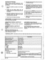
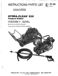
OWNER’S MANUAL
This manualcontains Important
Warnings and Instructions.Read the
manual and keepi!for reference.
/?>
“.?I
..........
:,’<...
..
{, .: I
:
,
.L
...
820-180 Rev A
j
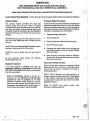
9 HP ENGINE
Model 2800 PRESSURE WASHER
PIN 820-175, Series A
28OOpsi’(lQBbar) OPERATING PRESSURE
3200 psi (224 bar) MAXIMUM WORKING PRESSURE
TABLE OF CONTENTS
......................... 2
5
startup.. .........................
6.
Shutdown, Flushing and Storage.... 8
Maintenance ......................
8
Troubleshooting Chart ...... .I.. ... 9
PartsDrawing8Lists ............. 10
Pump Sewice ....................
14
Accessories .....................
15
Technical Data ................... 15
Warranty ................ Back Cover
Warnings
. Installation .......................
\
v. ....
........
\
.
F
”
The SHERWIN-WILLIAMS COMPANY, CLEVELAND,OHIO 441 15
HIGH PRESSURE SPRAY CANCAUSE SERIOUS INJURY.
FOR PROFESSIONAL USE ONLY OBSERVE ALL WARNINGS.
..
.
Read and understandall instruction manuals before operating equipment.
,
FLUID lNJECTlON HAZARD
~
,
..
.~,
,
-
.
..
~.,.. ;., ~ "&
$ ~ p ~ q %%
;q y :
&A"YAr&.?
Pressure Relief Procedure
General Safety
To reduce the risk of serious bodily injury, including fluid
This pressure washer generates very
high fluid
injection and splashing
in the eyes or on the skin, always
pressure. Spray from the gun, leaks or ruptured
components can inject fluid through your skin and intofollow this procedure whenever you stop spraying for
more than 10 minutes, whenshutting down, and before
your body, and cause extremely serious bodily injuq
including the need for amputation. Also, fluid injected orchecking.or repairing any part of the system.
splashed into the eyes or on the can
skincause serious
1. Engage the trigger safety latch.
damage.
off.
2. .Turn the sprayer
N N E R point the spray gun or wand at-anyone or at any
part of the body.N W f R put hand or fingers over the
3. Remove theignition cable from the spark plug.
spray tip.
4. Shut off the water supply.
ALWAYS follow the Pressure Relief Procedure,before
cleaning or selvicing any part
of the sprayer.
5. Disengage the trigger safety latch and trigger the
gun to relieve pressure, and then engage the trigger
safety latch again.
NEVER try to stop or deflect leaks with yourharid.or
body.
6. Before long-term (overnight) storage or transporting of the unit, disconnect the water supply and turn
Be sure equipment safety devices are operating
off
the fuel supply valve.
properly before each use.
Spray Gun Safety Devices
Medical Treatment
Be sure all gun safety devices are operating properly
If any fluid appears to penetrate your skin, get
before eachuse. Do not remove or modify any part of
EMERGENCY MEDICAL TREATMENT AT ONCE.DO
the gun; this can cause a malfunction and result in
NOT TREAT ASA SIMPLE CUT. Tell the doctor exactly serious bodily injury.
what fluid was injected.
SAFETY LATCH: Whenever you stop spraying for a
NOTE TO PHYSICIAN: lnjection in the skin is a
moment, always set the gun safety latch
in the engaged
traumatic injuv. It is important to treat the injury
or "safe" position, making the gun inoperative. Failure
surgically as soon as possible. Do not delay
in accidental
to properly set the safety latch can result
treatment to research toxicify roxicify is a concern
triggering of the gun.
with some exotic coatingsinjected directly intothe
bloodstream. Consultation with a plastic surgeon or SPRAY TIP SAFETY: Use extreme caution when
cleaning or changing spray tips.
reconstnrctive hand surgeon may
be advisable.
_ . ?
2
.
..
i
'.
.
.
820- 180
EQUIPMENT MISUSEHAZARD
General Safety
System Pressure
. .
Any misuse of the pressure wisher or accesw)ries,
such Bs overpressu~~n~,
modifying using This sprayer can develop
high operating pressures.Be
sure that all spray equipment and accessories are rated
incompatible chemicals and fluids, or using or
to withstand the maximum working pressure of this
damaged parts, can
them to
and
exceed the working
in fluid injection, splashing in the eyes or on the skin, or sprayer.
other serious bodily injury, fire, explosion or property Pressure
of any component or accessory usedin the
damage. system.
Do
'
.
NEVER alter or modw any part of this equipment; doing
so could cause it to malfunction.
CHECK all spray equipment regularly and repair or
replace worn or damaged
p m immediately.
Chemical Compatibility
BESURE that all chemicals usedin the chemical injector
ALWAYS wear protective eyewear and appropriate are compatible with the wetted parts
of the hose, gun,
clothing. If using a chemical injector, read and follow the wand and tip, as given
inthe Technical Data (inside back
chemical manufacturer's literature for recommenda- cover). Always read the chemical manufacturer's
tions on additional protective equipment, such as a.
literature before using any chemicalin this pressure
respirator.
. .
washer.
HOSE SAFETY
'
p
J
\i...
(..?*,
.<+>?
-ui.
High pressurefluid in the hoses can be very dangerous. NEVER use a damaged hose. Before eachuse, check
entire hose for cuts;leaks, abrasion, bulging cover, or
If the hose develops a leak, split or rupture due
to any
If any of
damage or movement of the hose couplings.
kind of wear, damage or misuse, the high pressure
these conditions exist, replace the hose immediately.
spray emittedfrom it can causea fluid injection injury
or
DO NOT try to recouple high pressure hose or mend
it
other serious bodily injury or property damage.
with tape or any other device.A repaired hose cannot
contain the high pressure fluid.
A U FLUID HOSESMUST HAVE STRAIN RELIEFS ON
BOTH ENDS. The strain reliefs help protect the hose
from kinks or bends at or close to the coupling, which,
HANDLEAND ROUTE HOSES CAREFULLY Do not pull
can resultin hose rupture.
on hoses to move the pressure washer. Do not use
TlGHTENall fluid connections securely before each use. chemicals which are not compatible with the inner tube
and cover of the hose.
DO NOT expose Graco hoselo
coupling or
High pressure fluid can dislodge loose
a
temperatures above 200°F (93°C)or below -4OaF
allow high pressure spray to be emitted from the
(-40°C).
coupling.
FUEL ANDEMISSION HAZARDS
NEVER fill the fuel tank while the unit
is running or hot. odorless, invisible gas which can cause serious injury or
The fuel used in this unit is combustible and when death
if inhaled.
spilled on a hot surface can ignite and cause a fire.
ALWAYSfill tank slowly to avoid spilling.
NW€R alter the throttle setting, which is factory set.
NNER operate the unit in a closed building. The Tampering with this adjustment can damage the
exhaust contains carbon monoxide, a poisonous, pressure washer and will void the warranty.
820-180
3
MOVING PARTS HAZARD
Moving parts can pinch or amputate fingers or other and interiocks installed and functioning. Follow the
body parts.K€€P CLEAR of moving parts when starting Pressure Relief Procedure before checking or
to prevent discharging
or operating the pressure washer. servicing the pressure washer
high
pressure
fluid
from
the
gun.
NNER operate the pressure washer without all guards
TERMS
WARNING: Alerts user to avoid or correct conditions
that could cause bodily injuty.
.. .
NOTE Identifies helpful procedures and information.
CAUTION Alerts user to avoid or correct conditions
to the equipment.
that could cause damage
IMPORTANT
United States Government safely standards have been adopted under the Occupational Safety and Act.
Health
These
standardsparticularly the General Standards, Part 1910, and the Construction Standards, Part 1926-should be
consulted.
4
820 - 180
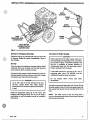
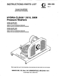
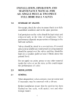
INSTALLATION
COUPLER
PRESSURE HOSE
CONNECTION
Figure 1
INLET WATER
CONNECTION 314"
GARDEN HOSE
Check for Shipping Damage
Connect to Water Supply
Check the unit for any damage that may have occurred
CAUTION
In shipping. Notify the carrier immediately if there is
Before attaching to the water supply, check your
any damage.
local plumbing code regarding cross- connection
to the water supply. A backflow preventer, P/N
Set Up
801-133, is available to prevent backflow 'of
contaminated
water into the fresh water supply.
If youare using a downstream chemical injector, install
Install
it
upstream
from the pump.
it between the pump unloader and the high pressure
hose, using the quick couplers provided.
If inlet water pressure is over60 psi (4.1 bar) a
Connect the high pressure hose between the pump (or regulating water valve, P/N 800-258,must be
installed at the garden hose connection.
chemical injector) outlet and the gun inlet. of
Both
these
connections are made with quick couplers.
Do not exceed 160°F (70°C) inlet water
temperature.
CAUTION
Up to 100 ft (30 m) of high pressure hose may
be used. Longer hoses may affect sprayer
3/4ainch (19 mm) ID from
Connect a hose with at least
performance, and chemical injector performance,
the water supplyto the unit's314 inch garden hose inlet.
t';:J
fi.!?.!,
2
The supply hose should not be more than
50 ff (15 m)
long.
Install the appropriate spray tip on the wand. See
Installing and Changing Spray Tips. If you are using aNOTE: The water source at the unit must have a
sandblaster kit, seeits separate manual for installation
minimum flow rate equal
to that of the unit(see Technical
instructions.
Data, inside back cover).
820- 180
5
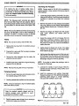
STARTUP
Always usethis startup procedureto ensure that the unit
is started safelyand properly.
1. Check oil levels.
Engine: Add SAE30 or low30weight detergent oil as
necessary.
Pump: Add SAE 20 or 30 weight non-detergent oil as
necessary.
NOTE This unitis equipped with a low-oil sensor that
shuts the engineoff if the oil level falls below a certain
level. If the unit stops unexpectedly, check both the oil
and the fuel levels. Check oil
the
level each time the una
is refueled.
2. Check fuel level.
WARNING
DO NOT refuel a hot engine. Refueling a hot
engine could cause a fire.Use only fresh, clean
regular or unleaded gasoline. Close the fuel
shutoff valve during refueling.
If the engineis cold, completely close the engine choke.
Grasp the starter rope, brace one foot
on the pressure
washer chassis and pull rope rapidly and firmly.
Continue holding the rope
as it returns. Pull and return
the rope until the enginestarts. In cool weather, the
choke may haveto be kept closed for10 to 30 seconds
before opening it to keep the engine running.
Otherwise, open the choke as soon as the engine
starts.
ifthe engine is warm, leave the choke open, or just partly
close Start the engine as describedin the preceding
paragraph. When it starts, be sure to open the choke
completely.
it.
CAUTION
On recoil start engines, never let the starter rope
return by itself.It could jam the recoil system.
7. ALWAYS engage the gun's trigger safety latch
whenever you stop spraying, even for a moment,
to
reduce the risk offluid injectionor splashing in the
eyes oron the skinif the gun is bumped or triggered
accidentally.
8. ALWAYS observe the following CAUTIONS to avoid
costly damageto the pressure washer.
completely
turned
on sure
before
I will
Cresult.AAlways
U be
T the
Ioperating.
water
O supply
N is 1
CAUTION
DOfiOTallowthe pressure washertoidleformore
than 10 minutes. Doing so may cause the
recirculating water to overheat and seriously
damage the pump. Turnoff the pressure washer
if it will not be spraying or cleaning least
at every
10 minutes. If heated inlet water is used, reduce
this time further.
4. Trigger the gun until water sprays from the tip
indicating that the airis purged from the system.
DO NOT run the pump dry, which will quickly
damage the pump. Be sure the water supply
is
fully turned on before starting the pump.
3. Turn on thewater supply.
Never run the unit dry. Costly damage to the pump
5. Open the fuel shutoff valve. Be sure the spark plug
ignition cableis pushed fiirmly onto the spark plug.
On those units equipped with an ignition shutoff
switch, put the switch in the "on" position and put
the throttlein the "run" position.
6. Start the engine.
DO NOT operate the pressure washer with the
inlet water screen removed. This screen helps
keep abrasive sediment out of the pump, which
could clog or scratch the pump. Keep this screen
clean.
DO NOT pump caustic materials; such materials
may corrode the pump components.
....
NOTE For easier starting, have one person start the 9. See the chemical injector or sandblaster kit manual
pressure washer while another person triggers the
for detailed cleaning informationif these accessospray gun.
ries are used.
6
820-180
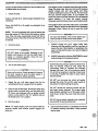
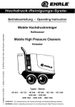
installing and Changing Spray Tips
Trigger Safety Latch
WARNING
To reduce the risk of serious bodily injuly,
including fluidinjection, splashing in the eyes or
on the skin, ALWAYS engage the trigger safety
latch whenever spraying stops, even for a
moment.
,
I
WARNING
To reduce the risk of serious bodily injury,
including fluid injection
or splashingin the eyes or
onto the skin, use extreme caution when
changing spray tips. ALWAYS follow the procedure below.
1
.
In the engaged position, the trigger safety latch
prevents the gun from being triggered accidentally by hand iforit is dropped or bumped.Be sure
the latch is pushed fully down
when engagingit or
1 cannot prevent the gunfrom being triggered.
. . .
See Figure 2.
1. Follow the Pressure
Relief Procedure:
2. Point the gun and wand away from yourself and
anyone else.
3. Without holding your hahd over the spray
tip (A),
pull back the quick coupler ring
(B). Remove the old
tip andlor install a new
one, and thenrelease the
ring. See Figure 3.
4. Be sure the tip is secure before starting to spray
again.
5. Tip holding holes are provided in the chassis.
CAUTION
To avoid blowing the o-ring out of the quick
coupler, due to the high pressurein the system,
TRIGGER SAFETY LATCH SHOWN ENGAGED
TRIGGER SAFEPT LATCHSHOGN
DISENGAGED
Figure 2
020 -100
Figure 3
7
MAINTENANCE
SHUTDOWN, FLUSHING
AND STORAGE , .
Observing regular maintenance intervals helps ensure
that you get maximum petformance and life fromthe
pressure washer.
WARNING
Pressure Relief Procedure
There is a break-in period for the engine and pump.
After changing the oil in these components following
their respective break-in periods, the interval between
required changesis longer.
To reduce the' risk of serious bodily injury,
including fluid injection and splashing
inthe eyes,
or on the skin, always follow this procedure
whenever you stop spraying for more than10
minutes, when shutting down, and before
checking or repairing any part of the system.
1. Engage the trigger safety latch.
If the unit is operating in dusty conditions,. these
maintenance checks should be made more often.
"
1
2. Turn the sprayeroff.
3. Remove the ignition cable from the spark
Plug.
4. Shut off the water supply.
-.
...i
..
WARNING
I
To reduce the risk of serious bodily injury,
including fluid injection, splashing
in the eyes or
on the skin or injuty from moving palts, always
follow the Pressure Relief Procedure Warning
before proceeding.
I
I
5. Disengage the trigger safety latch and trigger
Interval
6. Before long-term (overnight) storage or
Daily Clean water inlet screen and
filter. Check engine and pump
oil levels. Fillas necessaty.
Check gasoline level. Fill
as
necessary.
the gun to relieve pressure, and then engage
the trigger safety latch again.
transporting of unit, disconnect the water
supply, andturn off the fuel supply valve.
1. If the pressure washerwill be exposed to freezing
temperatures, drain all water outof the pump. If it
must be stored in freezing temperatures, flush the
unit with a 50% anti-freeze solution. Relieve
pressure. Flush the pressure washer before using
it again to remove the anti-freeze.
NOTE An anti-freeze flush kit,P/N 802-327,is available
to make flushing easier.
CAUTION
If water does freezein the pressure washer, thaw
it in a warm room before trying to startDO
it. NOT
pour hot water on or into the pump;
it may crack
2. After each use, wipe all surfaces of the pressure
washer with a clean, damp cloth.
3. Perform the appropriate maintenance. See maintenance chart.
After first 5
hours of
operation
What to do
Change engine break-in oil.
Drain oil when warm.Use SAE
30 or l o w 3 0 detergent oil.
Each 25 hours Clean and remove air cleaner
of operation foam. Wash with water and
detergent. Dry thoroughly. Rub
with oil and squeezeto
distribute oil.
After first50
hours of
operation
Change pump break-in oil. Use
SAE 20 or 30 non-detergent oil.
Each 100.
Clean or replace paper air
cleaner cartridge. Tap gentlyto
remove dirt. Change engine oil.
Use SAE30 or IOW-30
detergent oil.
Each 500
hours of
operation
Dr 6 months
SAE 20
Change pump oil. Use
or 30 non-detergent oil.
hours of
operation
or 3 months
820- 180
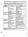
TROUBLESHOOTING CHART
/.m
.~&,.
,$,j,:,f;)
,.,.
,., ,,. .I
,. .
WARNING
1
To reduce the risk of serious bodily injury, including fluid injection, splashing in the eyes or on the skin or injury
from moving parts, always follow the Pressure Relief Procedure Warning before proceeding.
..
PROBLEM
CAUSE
Engine willnot stat?or No gasolinein fuel tank or carburetor.
is hard to start
Low oil
StarVstOp switch in Stop position.
Water in gasoline orold fuel.
.
"<.
Choked improperly.Floodedengine.
Dirty air cleaner filter. '.
Spark plug dirty, wronggap
type.
. . or wrong
Spray gun closed.
SOLUTION
Fill thetank with gasoline, openfuel shut offvalve.
Check fuel line and carburetor.
Add to proper level.
Move switchto Start position.
Drain fuel tank and carburetor. Use new fuel and dry
spark plug.
to clear
Open choke and crank engine several times
out gas.
Remove and clean.
Clean, adjust thegap or replace.
Trigger spraygun.
Engine missesor lacks Partially plugged air cleaner filter.
Remove and clean.
power
Spark plug dirty, wrong gapor wrong type. Clean, adjust thegap orreplace.
Low pressure andlor Worn or wrong size tip.
pump NnS rough
Inlet filter clogged.
Wornpackings.abrasivesinwaterornatura1
wear.
Inadequate water supply.
Fouledordirtyinletordischargevalves.Even
asmall particle can cause thevahre
l o stick.
Restricted inlet.
Worn inlet or discharge valves.
Leaking high pressure hose.
Water leakage from
underpumpmanifold
Water in pump
Worn packings,
Replace withtip of proper size.
Clean. Check more frequently,
Check filter. Replace packings. See PUMP SERVICE.
Check water flow rateto pump.
Clean inlet and discharge valve assemblies. Check
filter. See PUMP SERVICE.
Check garden hose, may
be collapsed or kinked.
Replace worn valves. See PUMP SERVICE.
Replace high pressure hose.
Install new packings. See PUMP SERVICE.
Humid air condensing inside crankcase. Change pump oil.
Worn packings.
Install new packings. See PUMP SERVICE.
Dil seals leaking.
Install new oil seals. See PUMP SERVICE.
Frequent or premature Scored, damagedor worn plungers.
hilure ofthe packings 4brasive materialin the fluid being pumped.
nlet water temperature too high.
3verpressurizing pump.
Install new plungers. See PUMP SERVICE.
nstall proper filtration
on pump inlet plumbing.
:heck water temperature; may not exceed 16OOF.
30 not modify any factory-set adjustments. See
EQUIPMENT MISUSEHAZARD.
5cessivepressureduetopartiallypluggedor :lean or replace tip. See Installing and Changing
iamaged tip.
spray lips.
lump running too long without spraying. W e r run pump more than 10 minutes without
;praying.
iunnina aumo d~~
10not run pump without
water.
jtrong, surging at the 'oreign particles in the inlet or discharge :lean or replacevalves. See PUMP SERVICE.
nletandlowpressureon 'dve or worn inlet andlor discharge valves.
he discharge side
~
~~~
~
9
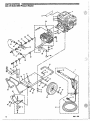
PARTS DRAWING
820-175 Model 2800 Pressure Washer
!.
!.
PARTS LIST
820-175 Model 2800 Pressure Washer
REF
PART
NO. NO.
DESCRIPTION
GUNB~WhJDASSEMBLY
1
800-392
2
3,
4
5
6
7
8
801-504
181-867
802-363
801-1 11
179-885
803-900
802-127
91
10
11
12
13
14
15
16
17
18
820-137
100-527
804-391
801-539
801-568
802-579
801-569
111-040
803350
801-941
19
20
21
801-009
154-636
101-545
800-743
23
24
25
803-740 WHEEL 8 TIRE ASSEMBLY
803-741 AXLE
801-546 SCREW, Cap, hex hd.
318-16 X 1.25
100.023 WASHER, Flat, 3/8
154-494 O-RING, Quick Coupler,1/4
(not shown)
156-082 O-RING, Quick Coupler,3/8
(not shown)
1
22
26
27
28
.
820- 180
lincl. 17. 191
BUMPER,'Rubber
LABEL, Warning
LABEL. Caution
NUT, Garden Hose
LABEL, Wamin
ENGINE, 9 hp, ondaOHV
SCREW, Cap, hex hd..
5/16-18~1.75
LABEL, ID .
WASHER, Flat;5/16
LABEL, Model2800
BUMPER
QUICK COUPLER,3/8 Male
HOSE, High Pressure,3/8 x 50'
COUPLING
NUT. Nylon Lock,5/16-16 10
GUN, Spray (see308-511)
SCREW, Cap. hex hd.
5/16-18 x 1
QUICK COUPLER. 114 Female
WASHER, Flat,;5/8
COlTER
PUMP- PIN
~
"
1
1
1
1
1
.31
~
'
~
32 101-566
33 m
1
34 801-012
35 801-367
4
36 804-398
1 37 804-051
14
38 803-083
1 40 801-1 10
1 41 800-124
42 800-125
2
1
43 800-126
1
44 800-127
45
801-907
46 801-905
47 156-849
4
48
801-709
49 800-745
4
50 802-627
2
1
51
803-869
52
801-523
2
53
8ol~ios
'
"
1
2A
lincl. 13. 14.15)
54 804-397
55
.~ 801-090
56
801-599
57 801-600
58
801-601
59 801-602
N a Nylon LOck,'3/&16
CHASSIS
GROMMET, Rubber
BUMPER, Rubber
BRACKn, Pump Support
FILTEiUSTRAINER
LABEL, Kee From Freezing
ADAPTER, garden Hose
RP ASSEMBLY, 0004
TIP ASSEMBLY, 1504
TIP ASSEMBLY, 2504
TIP ASSEMBLY, 4004
WASHER, Flat
ADAPTER
NIPPLE, Hex. 3/8 NPT
. PLUG
UNLOADER. Preset.2800 DSi
NIPPLE, Hex,
318 NPT x 114 NPT
HOSE, Bypa&
NIPPLE. 112 NPTT.EE,l/2NpT-~
QTY
1
1
1
4
1
4
2
.1
1
1
1
1
1
1
1
1
1
2
1
1
1
THERMAL RELIEFVALVE
QUICK COUPLER. 1/4 Male
Bare, 0004-~~'
TIF: Bare, 1504
TIP Bare.2504
TI+ Bare; 4004
e
i
4
8
AR
AR
DESCRIPTION
HANDLE
FRONT
LEG ASSEMBLY
.
800-377 Hs""'.
SEA SEMBLY
I
,
~
29 803-925
30 .800-641
.
..
~~
1
'
~
PART
NO. NO.
2
a
'
REF
ON
'
11
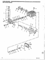
PARTS DRAWING
800-743 Pump Asse
I
I
,'
I
81
82
/
,/
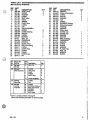
PARTS LIST
800-743 Pump Assembly
REF PART
NO. NO.
1
804-405
2 801-651
3 801-652
4
KIT123
5
KIT123
6 KIT 123
7
KIT123
8
KIT123
9 KIT 124
10 KIT124
11
KIT123
12 803-265
13 803-266
14 804406
15 803-268
16 804407
17 KIT23
18
804408
19 801459
22 804-409
23
804410
24 804-411
25 804-412
26
803-273
27 801-488
28 801-753
29
804413
DESCRIPTION
HEAD, Pump
SCREW
WASHER
O-RING
SEAT, Valve
VALVE
SPRING
CAGE, Valve
O-RING
CAP
VALVE ASSEMBLY
SCREW
COVER, Bearing
SPACER
O-RING
BEARING . 5
SEAL, Oil
CRANKCASE
DIPSTICK
GUIDE, Piston
ROD, Connecting
O-RING
COVER, Rear
SCREW
O-RING
SCREW, Cap
PIN
Klt
Repalr KR
Part No. No.
23
801458
Oil Seal
123 804-402
17
SEAL.Oil
4
O-RING
SEAT, Valve
VALVE
SPRING
CAGE, Valve
7
8
124 804-403
Valve Cap
130 804404
Packing
Assembly
.
DESCRIPTION
WASHER
RING, Anti-Extrusion
O-RING
PISTON
WASHER
NUT
O-RING
RETAINER, Packing
RING, Intermediate
PACKING
PACKING
RING, Head
SCREW, Cap
SCREW, Cap
WASHER.
WASHER
RING, Retaining
CRANKSHAFT
BEARiNG
O-RING
SCREW
WASHER
FLANGE, Gas
SEAL,Oil
WASHER
SCREW
QN
3
3
3
3
3
3
1
1
1
1
1
1
1
1
4
4
1
1
4
4
Ref.
No. Descrlpthx
Valve Assembly 5
6
I I
REF PART
NO. NO.
1
30
804414
8
31 803-919
8
32 803-918
33
804415
34 803-921
35 803-920
40 KIT130
41 KIT 130
42 KIT 130
43
KIT130
44
KIT130
45 KIT 130
8
2
48
801484
1
47
801482
1
48
801485
2
49 801-483
75
804416
1
76
804417
1
77 804-418
3
7a 804-419
3
79
804420
1
80 801-469
1
81
804421
5
82 804-422
1
83 803-278
1 84 803-292
3
OM
I:!* I
VALVE ASSEMBLY
9
10
40
41
42
43
44
45
O-RING
CAP
O-RING
OW._
3
6
6
6
6
6'
I I
6
6
6
1
RETAINER, Packing 1
RING, Intermediate 1
PACKING
1
PACKING
2
RING, Head
2
-
Item 11 consistsof items 4 through 8.
See Pump Assemblyillustration on previous page.
820- 180
13
-~
PUMP SERVICE
WARNING
To reduce the risk of serious bodily injury,
including fluid injection, splashing In the
eyes or
on the skin, orinjury from moving parts, always
follow the Pressure Relief Procedure Warning
before proceeding.
Servicing the Plungers
NOTE: Plunger repair kt, P/N 801-474 is available to
replace retainers, O-rings. washers and backup rings for
three cylinders.
1. Loosen the plunger retaining screw five
to six turns,
using an MlOwrench. Push the plungertowards the
crankcase to separate the plunger and retaining
screw.
NOTE The following metric wrenches are needed:
M10, M13 and M30. Repair k B are available. Refer to
the individual repair sections and the pump parts page 2. Remove the screw from the plunger and examine
the O-ring. backupring and copper
bearing/gasket
for more details. For the best results, use all parts in the
washer. Replace these parts,if necessary, usingkit
kits.
801474.
NOTE There aretwo different tool kits
to aid in servicing
the pump. P/N 800-298is used to ease installation of
packings. P/N 800-271' includes the itemsin 800-298
and tools to aid in the removal of packing retainers.
Valves
NOTE For a set of six valves, order P/N8011172.
1. Remove the hex plug from the manifold using an
M30'wrench.
plug and replace
2. Examine the O-ring under the hex
it if it is cut or distorted.
.. ... -
3. Remove the valve assembly from the cavity; the
assembly may come apart.
3. Remove the plunger and flinger from the plunger
shaft. Clean, examine and replace parts as
necessary.
4. Inspect the plunger shaft foroil leakage from the
crankcase. If leaking is obvious, replace the oil
seals. Otherwise, DO NOT remove these sealsas
they cannot be reused. An
oil seal kitis available to
replace the seals.
5. tightly grease the flinger and oil seal,if it is being
replaced, and replace themon the plunger shaft.
Then install the plunger.
the~outerend
6. Lightly grease the retaining screw and
of the plunger.Place the washer, O-ringand backup
ring around the screw and install the screw through
the plunger. Torqueto 14.4 ft-lb (19.5Nm).
4. Install the new valve. Install the O-ring and hex plug; NOTE If you.plan to replace the packings, referto
Servicing the V-Packings.
torque to75 ft-lb (103 Nm).
NOTE Retorque theplug after 5 hours of operation.
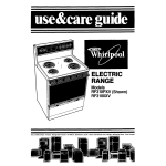
Pumping Section
1.
Remove the eight capscrews and lockwashers from
the manifold using an
M13 wrench.
7. Lubricate the outside of each plunger. Slide the
to
manifold onto the crankcase, being careful not
damage the seals.
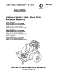
8. Install the capscrews and washers finger-tight.
Torque the screwsto 21.7 ft-lb (29 Nm) following the
tightening pattern (Figure 4). Uneven tightening
2. Carefully separate the manifold from the crankcase.
may cause the manifold
to bind or jam.
NOTE It may be necessaryto tap the manifold lightly
to loosen.
with a soft mallet
I
1
I
C
Keep the manifold properly aligned with the
to avoid
ceramic plungers when removing
damage to the plunger or seals.
3. Carefully examine each plunger for any scoring or
Figure 4
cracking and replaceas necessary.
14
820- 180
Servicing the V-Packings
NOTE: There are two types of packing kits: oneis
packings only, the other includes the packings, rings
and retainers.
1. Remove the manifold as outlined in the Pumping
Section.
2.
manifold. &amine the o-ring-and replaceit fi it is cut
or damaged.
3. Remove the v-packing and head ring. Pull
out the
intermediate retainer ring. Remove the second
v-packing and second head ring.
5. Thoroughly cleanthe packing cavitiesand examine
for debris and damage.
6. Lightly grease the packing cavities and then replace
the packings in the following order: head ring,
v-packing, intermediate ring, head ring, v-packing
and packing retainer with the
O-ring installed in the
retainer groove.
II
correct direction. Improperly installedparts will
cause a malfunction.
~
~
~~
~~
~
..
7. Reassemble the manifold as instructed
in Servicing
4. Inspect all parts and replace
as necessaty. the Plungers.
ACCESSORIES
(Must be purchased separately)
DOWNSTREAM CHEMICAL INJECTOR KIT ANTI-FREEZE FLUSH KIT 802-327
For flushing system with
50% anti-freeze solution prior
800-1 17
For injecting harsh cleaning chemicals downstream to transporting or storing pressure washer in below
from the pump. freezing temperatures.
UPSTREAM CHEMICAL INJECTOR KIT
800-257
For injecting mild cleaning chemicals upstream the
into
pump.
INLET PRESSURE REGULATOR 800-258
Regulates inlet water pressure to 60 psi (4 bar)
maximum.
BACKFLOW PREVENTOR 801-133
Prevent back-up of contaminated water into fresh
supply. Install upstream of pump.
TECHNICAL DATA
Engine (air-cooled,4 cycle)
9 hp Honda OHV
Gasoline Tank Capacity
6.2 quarts (6 liters)
Model 800-638
Water Pump Maximum Working Pressure 2800 psi (196 bar)
Water PumD Maximum Flow
3.5 aDm
-. 113.2
. Ium)
. .
Inlet Hose Connection
3/4" garden hose (f)
Weight
125 Ib (57 kg)
Dimensions
Length
Width
Height
Maximum Inlet Water Temperature 160-F
Wetted Parts
High Pressure Hose
Bypass Hose
Pressure Washer (including fittings)
820- 180
36" (914mm)
21 " (533mm)
23.5" (597mm)
(70°C)
Acrylonitrile and Buna-N cover and tube
Synthetic yam and EPDM
Anodized aluminum, Aluminumor bronze alloys, Brass Copper, Nylon-PTFE
composite, Ceramic, Buna-N
on phenolic,
303, 304,and 316 Stainless steel,
Polymide-12 thermoplastic, PTFE Carbon steel. Zinc plate,
with or withoutyellow
chromate
PTFE isa registered bademarkof the DuPont Cornpaw.
15
THE SHERWIN-WILLIAMS WARRANTYAND DISCLAIMERS
WARRANTY
Graco warrantsall equipment manufactured by
it and bearingits name to be free from defectsin materiil and workmanship on ths
date of sale by an authorized
Gram distributor to the original purchaseruse.
forAs purchaser's sole remedy for breach of this,,!;,,;:?
)
ranty, Graco will, for
a period of
twenty four months fmm the date of sale, repair or replace
pad
any
of the equipment proven
de;S:?:',- I
tiie. This warranty appliesonlywhen the equipmentis installed, operated and maintained
in accordance with Graco's written
me
;',
ommendations.
!,,
This warranty does not cover, and Graco shall be
notliablefor, any malfunction, damage or wear causedfaulty
by installation, mis;!
application, abrasion, corrosion, inadequate or improper maintenance, negligence, accident, tampering,
or substitution of non\.
...
Graco component parts. Nor shall Graco
be liable for malfunction. damage or wear caused by the incompatibility Graw
with
equipment of structures,' accessories. equipment or materials not supplied by Graco, or the improper design, manufacture, installation. operation or maintenance of structures, accessories. equipment or materials not supplied by Graco.
,, .,
,.
This warranty is conditioned upon the prepaid return of the equipment claimed
to be defectiveto an authorizedGram distributor
.'
for verification of the claim. If the claimed defect
is verified, Gracowill repair or replace freeof charge any defective parts. The
If inspection of the equipment does not disclose
any
equipment wilt be returned to the original purchaser transportation prepaid.
defect in material or workmanship. repairs
wil be made ata reasonable charge, which charges may include the
costs of pam,
!.
labor and transportation.
.>.
I,
i;,
fs
I
t..,
. .
DISCLAIMERS AND LIMITATIONS
The t e n s ofthis warrantyconstlute purchaser's sole and exclusive remedy and
& in lieu of any other warranties (express or
implied), lncludlng warranty of merchantablllty or warranty of fitness for a partlcular purpose, and of any non-contractual
liabilities, including product liabilities, based on negligence
or strict liability. Everyform of liabilityfor direct, special
or consequential
damages or lossis expressly excluded and denied. In no case shall Graco's
liabilityexceed the amount of the purchase price.
Any
action for breachof warranty mustbe brought within
two (2) years of the dateof. sale.
.
! ..
~
...
[i
;::
1'
EQUIPMENT NOT COVERED BY GRACO WARRANTY
Graco makesno warranty, and disclaimsall implied warrantiesof merchantablllty and fitness for a partlcular purpose, with
respect to accessories, equipment, materials, or components sold but not manufactured
Gram.
by These items sold. but not
if any, of their manufacturer. Gracowill provide
manufactured by Graco (such as engines, pumps, etc.) are subject to the warranty,
purchaser with reasonable assistance in making any claim for breach of these warranties.
.;:,>,
"
.,..
I;!.
/.:L
."
' I
l
i
c:'.
I
i;
,
.:
,,..
,. ,..
i.,
.
1
.;,:
,,
,,
The SHERWIN-WILLIAMS COMPANY, CLEVELAND,OHIO 44115
PRIMEDIN USA. 820-180
2-93
Revlsed2-93