1
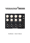
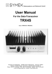
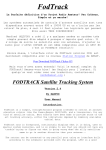
Modification of TS790E/A for UO-12 operation
Instructions for use of the IFD demodulator
Printed: 08.09.2006 16:40:00
Uplink (TX): any frequency (144-146 MHz, 430-440 MHz etc.), FSK-modulation 4800 up to 19200 kBaud,
Downlink (RX): 430-440 MHz, 38400/76800 Baud FSK (153 kBaud with wider filters (optional)).
Material required:
• SYMEK IFD-B-amplifier-mixer-demodulator board option 'TS790'
• two 1:3 rf micro-transformers, 2x30cm thin coax cable, wire, shielded audio cable and other hardware,
heatshrink tube and other parts as needed. The transformers are marked "7003* NEOSID". The both 50 Ω
pins are located at the side with the dot and the '7003' text, the 450 Ω pins at the side with 'NEOSID' text on
the upper side. In other words: If the pin marked with the dot is assumed pin 1 and the pins are counted
counter-clockwise (as usual with IC), the 50 Ω input is pin1+2 and the output is pin 3+4. However, the text
would be bottom up if you have pin1 (dot) oriented to the left. The transformer has a winding ratio of 1:3,
which results in a impedance ratio of the square, which is 1:9. With 50 Ω at pin 1+2, the impedance at the
pins 3+4 is 450 Ω to match the filter.
1. Transmitter (modulation):
The TS790 can be simply modulated with up to 19200 Baud if the following modifications are made:
Open carefully the transceiver case (bottom). Locate the connector 31 (FMD=frequency modulation).
The crystal oscillator 10.605 MHz) is located nearby. The connector is at the rear left side of the large
IF-board.
Solder a 10 kOhm resistor to the white wire which goes to the signal pin of connector 31. The other end
of the resistor is soldered to the inner connector of a 30cm shielded audio cable. The shield is connected
to ground (e.g. at connector 31, black wire).
For acessing this signal, ACC4 pin 3 could be used. This pin is not used with the original transceiver.
2. PTT (transmitter keying):
Pin 8 of the ACC4 connector is already available as PTT connection for keying the transmitter.
3. Demodulator output:
Open the top cover of the transceiver (front towards you). Locate the RF 430 MHz unit: it is found at
the right side below the power amplifier unit. To access the RF 430 unit, you have to remove all screws
around the cast aluminium assembly, including two screws at the rear panel. The RF430 unit is fixed at
the same cast aluminium part as the power amplifier but bottom-up. The aluminium part can be turned
with the plastic hinges so that the RF430 unit becomes easily accessible.
The total RF 430 unit is shielded with a tin cover. Remove this cover (many screws) first and totally
remove the printed circuit board. (some of the cables have to be plugged-out). You will have to make
changes at the solder side of this board:
Locate the dual gate FET mixer Q 203. (see photo, under L208). The drain of Q 203 goes originally
only to a tap of L 208. You have to carefully cut this trace between Q203 and L208.
Printed 8. Sep. 06
Installation manual for SYMEK IFD wideband receiver: Kenwood TS790 A/E
Page 1/6
TS790, case opened, RF-unit with added coax cables shown.
IFD-Input <--> Mixer out
IFD Output <--> Filter input
Solder side of RF 430 unit with the added transformers.
You can see where to cut the trace (3 blue lines, center)
Note: the SMD-type transformes are connected with short 0.3 mm copper enamelled wires
Remove parts of the green solder resist to solder the ground connection
Top side of the transceivers case,where the IFD can be installed bottom-up.
Printed 8. Sep. 06
Installation manual for SYMEK IFD wideband receiver: Kenwood TS790 A/E
Page 2/6
Connection to mixer output:
Use a 3:1 step down transformer. Connect one of the 450 ohm input pins to the drain of Q 203, where
the tap of L208 was connected before. The other 450 Ohm pin is soldered to the joint of R213 (56 Ohm)
/ C218 and L208. Connect the 50 ohm side of the transformer to a thin 50 ohm coax cable. Cable shield
is soldered to ground. So, the FET is supplied via the 450 Ohm winding with power.
Feed the cable marked "mixer" below the fan motor to the bottom compartment of the transceiver.
Version with 1:3 transformers 50:450 Ohm
Note: with the SMD-transformers, the input and output is not dc-coupled. The 50 Ohm in and out is
just the 50 Ohm winding of the transformers. The 50 Ohm side of both transformers go to the input and
output of the IFD via a thin 50 Ohm coax cable. The other pin of the 50 Ohm windings are connected to
ground.
Connection to filter input
Use a 1:3 step up transformer. Solder the 450 ohm output to the tap of L208 (where the Q 203 mixer
was connected before), the other pin to the joint of R213 (56 Ohm) / C218 and L208. Connect the 50
ohm input of the transformer to a thin 50 ohm coax cable. Cable shield is soldered to ground.
Feed this cable, marked "filter" below the fan motor to the bottom compartment of the transceiver.
Carefully reinstall the RF 430 MHz board. Use insulating tape to avoid short circuits and damage of the
transformers at the solder side of the board.
Important: Due to the differences in impedance, L208 needs to be readjusted now. Receive a weak
signal and carefully turn the core of L208 to maximum S-meter reading if the transceiver.
to IFD RF-IN (Mixer)
to IFD RF-OUT (Filter) (Mixer)
Installation of the IFD board
Printed 8. Sep. 06
Installation manual for SYMEK IFD wideband receiver: Kenwood TS790 A/E
Page 3/6
There is a corner at the bottom compartment of the TS790, where you can easily install the little IFD
circuit board: Find the unused hole with a M 2.5 thread in the frame of the transceiver. It is in the front
left corner (transceiver bottom up). You can directly fix the IFD to the spare thread using a single M 2.5
x 6 screw. As the IFD is mounted top-down, you have to solder all connections before:
1. solder the coax cable "mixer" to the RF-IN (terminal M1) (shield to M2)
2. solder the coax cable "filter" to the RF-OUT (terminal M11) (shield to M12)
3. solder a 30 cm red wire to terminal M90 (+12V). The other end of this wire is soldered to Pin 7 of the
ACC4 connector at the rear side of transceiver. (permanent 12Volt connection)
4. The demodulator output (terminal M63, data out) goes to ACC 4 Pin 5 (originally unused) via a thin
shielded audio cable.
5. Ground connection for power supply is not necessary (cable shields are already grounded).
4. Connection of the packet-radio-controller (TNC):
You need a 3 wire + screen cable from the TS790 to the packet controller. When using the 8 pin DIN
Type H (pins not arranged in a circle, pin 6+7 are nearer to circumference) connector ACC 4 connector
as described above, you only need an apropriate cable between the ACC 4 connector and TNC:
Pin 2: Ground (connect to TNC pin 2 GND
Pin 8: (center pin) PTT (connect to TNC pin 3: PTT)
Pin 3: Modulation (connect to TNC pin 1: Mod)
Pin 7: 12,5 Volt supply (not used)
Pin 5: data output (connect to TNC pin 4: Demod)
(RSSI output may be connected elsewhere if necessary)
5. Setup and test:
Before reinstalling all covers, check if the transceiver works exactly as before. For best RX sensitivity,
the resonant circuit L 208 needs to be readjusted: Apply a 1 to 10 microvolt signal and tune L 208 to
maximum S-meter reading. Because of the additional IF amplifier, the s-meter may show few dB
difference.
In the Kenwood service manual 430 Mhz receive system sensitivity adjustment is as follows:
1. apply 3.2-100 uV FM signal, 1 Khz modulation, 5 Khz deviation (I used 3 uV at 440 Mhz).
2. Tune, in sequence, L214, L215, L210 for maximum S-meter reading, then repeat
3. Tune, in sequence, L211, TC203, L208, L209 for maximum S-meter reading, then repeat
It requires this full series for me to get the sensitivity back up. Just adjusting L208 only helps a very
little. TC203 was a big help! These really are easy adjustments. Only L209 is a little "touchy", the
others are broader at the peak. Although the service manual is quite specific about signal level,
Printed 8. Sep. 06
Installation manual for SYMEK IFD wideband receiver: Kenwood TS790 A/E
Page 4/6
deviation, etc. I suspect the average ham could do this with any weak, constant strength signal source in
the 435 Mhz band.
Adjust the output level of the TNC to get the desired frequency deviation / modulation index. Do not
overmodulate as the transceiver will totally switch off the modulator. The modulator should work
perfectly for all FSK baudrates from 9600 to 19200 baud. Note: the input voltage determines the
bandwidth of the transmit signal. You will need more signal amplitude for higher baudrates.
The RSSI output should be near zero volts (<0.1 µV signal) and go up to 4 volts (1 mV rf input)
When receiving a 19200, 38400 or 76800 baud signal, there will be a perfect eye at the data output. The
output voltage at 38400 Baud is typically 0.5 volt pp.
6. Questions and Answers:
Q: why is the IF signal fed through the IFD? Wouldn't it be easier to connect the IFD in parallel to the
mixer output?
A: directly after the mixer, the signal passes a quartz filter. As with every filter, the input impedance
varies significantly with frequency: within the passband, the filter is matched, outside the passband, the
filter reflects the signal. The amplitude spectrum at the filter input shows a sharp notch at the passband.
Attaching a parallel demodulator here would cause severe distortions due to the varying load. So, the
signal after the mixer has to be buffered. The amplified signal is attenuated again to get the same (or a
few dB more) signal level as without amplifier.
Q: is a AFC output available?
A: There is an unconnected pair of pins on the printed circuit board (M60/M61). These pins can be
connected to the joint of R52/C52 (DET out) via a 100 kΩ resistor to pin M60. The voltage measured at
this pin will depend on the center frequency of the received FM signal.
Q: how do I decode a fast packet-radio signal of 38kBaud or more?
A: The TNC2 with the Z80 processor cannot decode signals beyond 19200 Baud. The newer TNC3 or
TNC31 series is capable of receive and transmit baudrates up to 1 Mbit/s. There are modems with all
common baudrates (9600, 19200, 38400, 76800, 153600 and above). Special modems with different RX
and TX speed (e.g. TX 9600 / RX 38400 for UO-12) are also available. When using WISP software
with a TNC3 packet controller, you may use the modem 2 for receiving and modem 1 for transmitting.
As WISP uses kiss-mode, both modems are received simultaneously, the data will be transmitted via the
default port 1.
Options and Jumper assignments:
J80:
Close if fundamental quartz oscillator is used. L80 is NOT used in this case.
Open if overtone crystal oscillator mode is used. L80 must be installed.
J82+84 Close to enable internal local oscillator.
Open if external oscillator is used. X80, L80 may be omitted.
J85:
Close if external local oscillator is to be used.
Open if internal local (crystal) ostillator is used.
J91:
Close if the supply voltages is to be derived from the IF input or IF output pin. (e.g. FT736). L1/L16
installed.
Open if the IFD is to be supplied via the 12V in pin. L1/L16 must be removed for IC821 operation!.
J92:
Close if the internal voltage regulator is used
Open if the IFD is supplied from an external regulated 5V source.
R74:
Offset adjust. Adjust for 0.1 Volt RSSI output with no input signal
R76:
Gain adjust: Adjust for 4 Volt RSSI at -50 dBm input signal level. R76 and R74 habe to be adjusted 2-3
times for best result.
The IF output before the limiting amplifier is available at pin 'IF out'. To use this feature, install U100 and L100.
For best symmetry, apply a wideband modulated FSK signal to the IF input and adjust L44 to maximum af
signal (1 Vpp) at data out.
L12 and L13 can be readjusted for maximum signal (measure RSSI signal) with a weak (-90 dBm) input signal.
With the input open, there should be approx. 2 V peak-peak noise at the data output.
For applications, where larger input signals are present, the input attenuator R1, R2, R3 may be used. Normally,
a capacitor is used for R2 and R1/R3 are open.
The oscillator components depend on the quartz frequency and fundamental/overtone mode.
The values of L12, L13, C10 to C15 depend on the desired IF input frequency.
The filters F20 and F30 are selected according to the desired IF bandwidth:
Printed 8. Sep. 06
Installation manual for SYMEK IFD wideband receiver: Kenwood TS790 A/E
Page 5/6
Modifications IFD option TS790: Oscillator: quartz TQ730518 / 65,225 MHz for IF 75,925 MHz (standard), R80: 560Ohm, L80: 0,33 uH, C80: 22pF, C81: 33pF, C82: 33pF.
Values for the band filter: C10: 68pF, C11: 12pF, L12: 0,33uH, C12: 2.2pF, (C13: 2,7pF), L13: 0,33uH, C14: 22pF, C15: 22pF.
Between joint U1 Pin 3 / R10 and the joint C11 / C10 a 22 Ohm resistor was added to reduce influence of the filter input impedance on amplifier gain.
Typical voltages (measured wit dc voltmeter):
U1 (ERA-3 Amplifier) Pin 1: 2.6 V
U1 (ERA-3 Amplifier) Pin 3: 3.5 V
Q 80 (Oscillator) Base 3.2 V
Q 80 (Oscillator) Emitter 2.8 V
Printed
8.
Sep.
06
U2 (IF-IC) Pin 1: 1.1 V
U2 (IF-IC) Pin 4: 4.2 V
U2 (IF-IC) Pin 8: 4.6 V
U2 (IF-IC) Pin 20: 2.6 V
Installation
manual
for
U2 (IF-IC) Pin 18: 1.3 V
U2 (IF-IC) Pin 16: 1.3 V
U2 (IF-IC) Pin 14: 1.3 V
U2 (IF-IC) Pin 11: 1.5 V
SYMEK
IFD
wideband
receiver:
Kenwood
TS790
A/E
Page
6/6