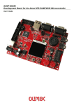
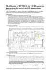
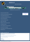
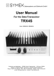
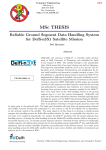
1
Datensysteme und Elektronik GmbH
Hardware-User-Manual for the 16 bit
High Speed Packet-Radio-Controller
TNC3S
Printed: 09.11.02 17:40 (T3HARD-G)
SYMEK Datensysteme u. Elektronik GmbH, Ulf Kumm, DK9SJ, D-70597 Stuttgart, Joh.-Krämer-Str. 34
Phone: +49 711-76 78 923, Fax: -76 78 924, Hotline: -76 54 911, http://symek.com, [email protected]
Table of contents
PREFACE ............................................................................................................. 2
TECHNICAL DATA TNC3S.................................................................................. 2
GETTING STARTED............................................................................................. 3
CONNECTING OF TNC3S TO IBM-COMPATIBLES (PC) .............................................................. 4
Interface cable TNC-PC ................................................................................................. 4
Interface-setting .............................................................................................................. 4
TOTAL RESET WITH TNC3S ................................................................................................... 5
POWER SUPPLY OF TNC3 ..................................................................................................... 5
CONNECTING THE RADIO TO TNC3................................................................. 5
INSTALLATION OF A MODEM BOARD ............................................................. 5
MODEM INTERFACE, CONNECTION OF OTHER MODEMS ............................................................. 6
Digital Interface, (Modem-Disconnect-Connector)........................................................ 6
Pin Assignment Modem-Disconnect ............................................................................... 6
NRZ and NRZI-Coding ................................................................................................... 6
SPECIAL INTERFACES + MODEMS ........................................................................................... 7
MEANING OF DIP-SWITCHES AND LIGHT EMITTING DIODES ....................................................... 7
Light emitting Diodes (LEDs): ....................................................................................... 7
Setting of the 8 DIP-Switches ......................................................................................... 7
JUMPERS IN TNC3, MODIFICATIONS ....................................................................................... 8
Jumpers J2, J3, J5 and J6: 'EPROM size' ...................................................................... 9
Jumper J1, J4, J7, J8 and J9: 'RAM size' ....................................................................... 9
Pins for special applications........................................................................................... 9
Other Jumpers and special parts .................................................................................. 10
Set-up for combined 1200/9600 Baud-Digipeater....................................................... 10
Grounding the TNC3 Case ........................................................................................... 10
RF-Interference?........................................................................................................... 10
UPDATES, NEW EPROMS ................................................................................................... 11
SCHEMATICS TNC3-K (DIGITAL PART) .................................................................................. 12
SCHEMATICS TNC3S-K (MODEM-INTERFACE)....................................................................... 13
SCHEMATICS TNC3S-K (CLOCK, BATTERY, ADDRESS-DECODER) .......................................... 14
COMPONENT LOCATION TNC3S-K ...................................................................................... 15
COPYRIGHT ON TNC HARD AND SOFTWARE ............................................. 16
ADDRESSES AND LITERATURE ..................................................................... 16
INDEX.................................................................................................................. 17
PREFACE
The expression 'packet-radio' appeared first in 1982. From the first experiments, a world-wide data net for
amateur radio has been developed.
Meanwhile, packet-radio has become one of the most important operating modes. The reason therefore
is that packet radio is not only used by amateurs with a special interest on digital operating modes, but
also by a increasing number of amateurs who prefer packet-radio as a very useful tool for information
interchange and spreading all kinds of news regarding all fields of the hobby.
To be up to date as a radio-amateur, it is important to read the mailboxes occasionally. To write a short
memo to a friend, there is nothing better as to write a mail via packet-radio. While lying in wait for a rare
short-wave dx-station, it is necessary to have access to a packet-dx-cluster.
Until 1992, the TNC2-series of packet-radio-controllers with the 8 bit Z80 processor had been standard.
The demand for higher speed and smarter software lead to the development of the TNC3S by the students Joachim Scherer, DL1GJI and Roland Alber, DG8GAD. The final layout for series production and
the modem design was added by Ulf Kumm, DK9SJ with the SYMEK company.
With the TNC3S, you own a device which represents the top of today's packet-radio technology. It is
suited for operating a user's standard packet station as well as for special applications as digipeater,
mailbox-tnc, high-speed-controller etc.
The manual will help you to use the hardware of TNC3S. About connecting the radio, please refer to the
manuals supplied with the modems, for information on the software, please use the software manual
supplied with the TNC or with the updates. If there are problems to set up and operate the TNC3 please
read this manual carefully. If your problem cannot be solved with the manual, ask your dealer for help.
This hardware manual supplied with your TNC remains valid, even when the software has been changed.
So keep it and replace only the software-manual when updating the programs in Flash-EPROM.
18. Aug 2000 Ulf Kumm, DK9SJ
Important: The information in this manual is valid only for printed circuit board version K.
TECHNICAL DATA TNC3S
(VALID FOR PCB VERSION K, MANUFACTURED FROM MID 1997)
Power Supply:
12 v DC (min. 8,0 V, max. 30 V), typ. 65 mA (Values without modems, at 12 v).
Internal supply voltage: 5 v. switchmode regulator: MAX831.
Dimensions: ca. B=175, T=130, H=42 mm, masse ca. 600 gram
Computer Interface:
RS232 (+/- 10 v signals), 25-pin Sub-D female connector.
Baud rate: 1200; 2400; 4800; 9600 Baud; 19,2; 38,4; 57,6; 115,2 kbaud (230,2 kbaud)
Parity: none , word length 8 Bit (may be altered by software settings),
Output: Data out (Pin 3), Input: Data in (Pin 2), no hardware-handshake.
Modem Interface 1+2: (optional 3 interfaces if RS232 is omitted)
CMOS -level 5 volt. TXData, TXClock, RXData, RXClock, RTS CTS, DCD, + 5 volt,
reset, ground. The TNC3 is able to deliver up to 350mA supply current for both modems.
Connection to the TNC3 motherboard via 20 pin connectors and a 20 wire ribbon cable.
2 modem boards (120x80mm each) may be built-in.
Bus-Interface: (optional)
The processor data bus (D0 to D7) and the address A1 to A4 and a programmable chip select
are available on separate solder pins for special extensions.
LED-Display:
Power (5 Volt), STA 1, CON 1, STA 2, CON 2 + Modem-LEDs
Microprocessor:
CPU Motorola MC 68302-15 MHz, in 132-pin SMD-case with microprogrammable on-chip RISC ProcesTNC3S Hardware
Page 2
sor for data communication, internal data bus, 6 DMA-channels, programmable chip-select outputs,
24 Bit address, 16 Bit data bus
Program memory (Flash-EPROM):
16 Bit wide, Standard: 256 Kbytes Flash-EPROM, (256 kByte UV-EPROMs can be used as well)
Data memory (CMOS-RAM): (battery buffered)
16 Bit wide, 64 Kbytes up to 2 Mbytes (standard: 64 Kbytes, recommended: min 256 Kbytes)
RTC real time clock:
Battery buffered (year, month, day, hour, minute, second).
DIP-switches:
8-pins for selection of software-options (Autostart) and baud rate
Reset and Watchdog: MAX 818 supervisory circuit with software-trigged watchdog
Battery: 3 v lithium-battery with automatic switchover by MAX818
GETTING STARTED
You are already familiar with TNC and packet-radio? This page will give you all necessary information to
start using your TNC3.
Power Supply:
12 volt (8-30 volt), max. ca. 150 mA. Connector 5 mm. Positive inner, negative outer contact.
Computer connection, Interface
RS232 via a standard serial cable 1:1. . 25-pin male connector to TNC, 25 or 9 pin female connector to
PC. Baud rate can be pre-set with dip-switches 1, 2 and 3.
SW 1 SW 2 SW 3
Baud
SW 1 SW 2 SW 3 kBaud
230400*
19,2
⇓
⇓
⇓
⇑
⇓
⇓
2400
38,4
⇓
⇓
⇑
⇑
⇓
⇑
4800
57,6
⇓
⇑
⇓
⇑
⇑
⇓
9600
115,2
⇓
⇑
⇑
⇑
⇑
⇑
Other baudrates may be set with the command ‘rsconf’. See software-manual.
*: only with special RS232 driver IC installed
Software selection (DIP-Switches 4-8)
SW 4 SW 5 SW 6 SW 7 SW 8 Autostart-Software
(16)
(8)
(4)
(2)
(1)
(binary value of DIP-switch)
DIP 0: TNC3S-operating system
⇓
⇓
⇓
⇓
⇓
DIP 1: Turbo-Firmware
⇓
⇓
⇓
⇓
⇑
DIP 6: SYSTEST (German)
⇓
⇓
⇑
⇑
⇓
DIP 7: SYSTESTG (English)
⇓
⇓
⇑
⇑
⇑
DIP 8: RSKISS (Kissmode)
⇓
⇑
⇓
⇓
⇓
DIP 9: TNC3BOX (English)
⇓
⇑
⇓
⇓
⇑
DIP 10: TNC3-mailbox (German)
⇓
⇑
⇓
⇑
⇓
DIP 11: TurboFirmware Hayes-Mode
⇓
⇑
⇓
⇑
⇑
DIP 31: total reset. erase RAM
⇑
⇑
⇑
⇑
⇑
The list may vary, depending on the programs used. See software-manual.
Connection of the Radio
Connection identical to other TNC with a 5 pin DIN connector. See the specific modem manuals.
Pin
1
2
3
4
Name
MIC
GND
PTT
SPKR
Function (radio connection pin)
microphone, modulator, output of the TNC (audio)
ground, 0 volt, screen.
push-to-talk key, , closes to ground when transmitting.
loudspeaker, demodulator, audio input of TNC.
Start
Connect everything (radio, computer, power) - start PC-program - ready.
TNC3S Hardware
Page 3
Note: All timer settings are given in ms (milliseconds) with TNC3, e.g. TX-Delay = 250 ms!
Problems?
Normally there should be no problem so far. If anything does not run as expected, you should go on
reading the manuals for specific information on TNC3 operation.
Connecting of TNC3S to IBM-compatibles (PC)
Interface cable TNC-PC
The PC are available with a 25 pin male connector (standard for COM2) or with 9 pin male connectors
(COM 1 and most modern PC after 1998) You need a 25-pin or 9-pin sub-d female connector for the
computer and a 25 pin male sub-d connector for the TNC.
Many PC use a 9 pin connector as COM1 for the mouse connection and a 25 pin for COM2.
The TNC3 uses in normal operation only the signals TxD and RxD (pins 2 and 3). With some PC it can be
necessary (depending on software) to wire the hardware-handshake: connect pin 4 + 5 and the pins 6, 8
+ 20. This is required e.g. when the TNC is to be addressed as a modem using Windows 95.
Here the circuit for a serial cable with 25-pin or 9-pin female connector. (Pins for 9-pin connectors in
brackets)
Connections in parenthesis may be omitted
male cont.(PC)-female(cable)---male (cable) - female (TNC)
( Pin 8
[Pin 1] >-------(pink)--------> Pin 8 )
Pin 3
[Pin 2] >-------(brown)-------> Pin 3
Pin 2
[Pin 3] >-------(green)-------> Pin 2
( Pin 20
[Pin 4] >-------(grey)--------> Pin 20)
Pin 7
[Pin 5] >-------(white)-------> Pin 7
( Pin 6
[Pin 6] >-------(blue)--------> Pin 6 )
[Pin 7] >-------(yellow)-- ----> Pin 4 )
( Pin 4
( Pin 5
[Pin 8] >-------(red)---------> Pin 5 )
Interface-setting
The TNC normally uses the following settings:
Baudrate:
19200
Parity:
N
(none)
Bits/character: 8
Stop bits
1
How to define these settings depends on your specific PC-software. Normally, the parameters are filled-in
in a menu or configuration file and set automatically at restart of the program.
TNC3S with modems, without case
Total reset with TNC3S
If absolutely all data has to be erased from CMOS-RAM of TNC3, set the DIP-switches to "31" and connect supply power for some seconds. After that, all data is erased and you can go back to normal DIPswitch setting. As long as the switches are on "31", there is no normal operation possible. The 'HALT'LED inside the TNC will blink with every reset.
If you have updated the TNC3 software or if you cannot access the TNC3, a reset is necessary.
TNC3S Hardware
Page 4
1
2
3
4
5
6
7
8
Switch
×
×
×
⇑
⇑
⇑
⇑
⇑
DIP 31: Reset-routine
you should back-up the data stored in RAM on a disc before erasing. So, you may restore it later.
Power Supply of TNC3
The TNC3S is supplied with direct current (DC). The current drain is about 75 to 200 mA at 13 Volt, the
TNC needs a supply voltage in the range of 8 Volt but not exceeding 30 Volt. Simple power supply jacks
may be sufficient but make sure that the No-load voltage is always less than 30 Volt.
The best is to supply the TNC3 from a regulated 12 or 13,5 Volt supply as used for radio transmitters etc.
In most cases, such a supply is available in every amateur station.
If the supply voltage is too low, the microprocessor will not start properly.
Check the supply voltage to make sure it is within the limits.
The power drain depends on the supply voltage. The higher the voltage,
the lower the current! But the power consumption of the TNC depends also
on the software which runs on the processor. The e.g. Turbo-Firmware
utilises the low-power-mode of the 68302 microprocessor and saves a lot
of current. The built-in modems consume a significant part of the total supply current. (see the data of the modems)
The MAX831 switch mode regulator may be replaced by a serial regulator Microprocessor of TNC3S
type like LM7805, which is cooled by fixing it to the right side of the aluminium case.
CONNECTING THE RADIO TO TNC3
The connection of the receiver and transmitter is explained in detail in the manuals of the modems. In
general, the radio is connected by a 5 pin DIN-connector with the following pinning:
Pin 1: MIC
af input of radio, output of TNC
Pin 2: GND
Ground
Pin 3: PTT
ptt, transmit-switch, closed to ground
Pin 4: SPK
af-output of the radio receiver
Pin 5:
not used, see modem-manual
(View to solder side of plug)
4
1
2
5
3
Important: the five pins are not numerated in row.
You find tiny figures on the black insulating body of the plug.
INSTALLATION OF A MODEM BOARD
First read the manual which is supplied with the modem. There are sometimes configurations necessary
which can be done only before the modem is installed and all parts of the modem are accessible.
Disconnect the TNC3 from the supply. Remove the TNC3 front panel (4 screws) and pull the top panel
fully towards you. After installing the 20-pin ribbon connector to the modem correctly, fasten the modem
top side down on the 4 (or only 2) hex bolt spacers with M3 screws. The DIN receptacle and the controls
(trimmers, switches) must appear exactly behind the access holes in the rear panel. Now close the TNC3
case again. Make sure, that the LED's fit exactly in the front panel holes.
With the system test program you should check if the TNC recognises the built-in modem properly. If all is
ok, connect the radio to the modem.
Note: As the modems are built-in top side down, the DIP-switches are enumerated in the opposite way to
the DIP-switches of the TNC3 main board.
Modem Interface, Connection of other Modems
Digital Interface, (Modem-Disconnect-Connector)
The Modems are connected to the TNC3S main board with a 20 wire ribbon cable. The cables are supplied with the main boards, not with the modems.
TNC3S Hardware
Page 5
If you intend to connect another modem with an HDLC-interface (e.g. Vanessa-board, RMNC or special
modems), a longer cable may be used and the modem may be mounted externally. The cable length is
not critical, but the radio interference (EMI) may become worse when using longer, unshielded connections.
The pin assignment of the modem disconnect cable is the same as recommended by DF9IC high-speedmodems. All even numbered pins are connected to ground, which gives a good shielding effect. The
digital signals use CMOS-TTL-levels (0 / 5 Volt), the modems are supplied with 5 V DC via the 20 pin
connection. (rating max 300 mA for both modems)
Pin Assignment Modem-Disconnect
Pin
1
3
5
Signal
+ 5 Volt
+ 5 Volt
Reset
Function
Power Supply of the modems by the TNC
Power Supply of the modems by the TNC
Reset-from / to TNC
(both directions,
low=reset)
7
DCD
AF carrier detect (from Modem to TNC)
9
CTS
Transmitter clear to send (from modem to
TNC)
11
PTT
Transmitter keying (from TNC to modem)
13
TxD
Transmit Data (from TNC to modem)
15
RxD*
Receive Data (from modem to TNC)
17
TXC
Transmitter Clock (from modem to TNC)
19
RXC*
Receiver Clock (from modem to TNC)
*: RxD and TxD are NRZI-coded !
Pin
2
4
6
Signal
Ground
Ground
Ground
8
10
Ground
Ground
12
14
16
18
20
Ground
Ground
Ground
Ground
Ground
NRZ and NRZI-Coding
The AFSK-modem e.g. transmits one of two possible sine wave tones. With packet-radio, the changing of
one tone to the other represents the transmission of a logical "1" (HI). If a "0" (LO) is to be transmitted,
the tone remains unchanged. With this way of encoding (NRZI) it makes no difference which tone is
transmitted. Important is only the fact, that the tones changes.
The former TNC2 however, generates at its modem-interface not this NRZI-Signal, but the digital data
stream itself. So, all TNC2 modems have a flip-flop for transmitter and receiver which take care of this
NRZ/NRZI-translation.
The TNC3 generates already the NRZI-signals, there is no need to make any NRZ-NRZI translation
within the modem circuit. In simple (e.g. AFSK-) modems, you may feed the data signal before or behind
the corresponding flip-flop, generally, a 74HC107 is used for that. With DF9IC-derived FSK (G3RUH)
modems, the NRZ-NRZI translation is done by the T and R GALs. Whether these modems generate / use
NRZ or NRZI data depends only on the contents of these two GALs.
Special Interfaces + Modems
For modem development, a breadboard PCB is available (80 x 120
mm), which fits exactly in the TNC3 modem slot.
Meaning of DIP-Switches and Light Emitting
Diodes
On the front panel, there are 5 LED's, on the rear panel, you find 8
DIP-switches on the TNC3S main board (this is the lower board) for programming the terminal baud rate
and selecting the software options.
Light emitting Diodes (LEDs):
The PWR-LED (yellow)
This LED is operated by the regulated 5 V of the TNC, whenever the supply voltage is connected.
The CON-LED (Channel 1 and 2) (green)
This LED is controlled by software and may have different meanings, dependant of the selected software.
When using Turbo-Firmware or TF, it means: there is a connect at the selected radio channel.
The STA-LED (Channel 1 and 2) (red)
TNC3S Hardware
Page 6
This LED is controlled by software and may have different meanings, dependent on the selected software. When using Turbo-Firmware or TF it means: the TNC has data in its receive buffers, which has not
been transferred to the computer. With the TNC3BOX software, flashing STA-LEDs mean: Mail for the
box-operator arrived. To cancel flashing: read and erase the mail.
The DCD-LED of the Modems (yellow)
This LED will light whenever the modem recognises the radio channel busy. (see also the modem manual)
The PTT-LED of the Modems (red)
This LED shows if the transmitter is keyed. (see also the modem manual)
Setting of the 8 DIP-Switches
The levers of the DIP-switches may be switched by a pointed object (do not use pencil or ball pen) off
(lever up) or on (lever down). As these switches close to ground, a open switch means a logic "1) (HI),
closed switches represent a "0" (LO). In the following list, the levers are represented by arrows:
⇑
Switch up = open = logic "1"
⇓
Switch down = closed = logic "0"
×
don't care
Switches 1, 2 and 3 : Terminal Baudrate
with these switches, the baud-rate for the communication between TNC and computer may be selected.
4
5
6
7
1
2
3
⇓
⇓
⇓
×
×
×
×
⇓
⇓
⇑
×
×
×
×
⇓
⇑
⇓
×
×
×
×
⇓
⇑
⇑
×
×
×
×
⇑
⇓
⇓
×
×
×
×
⇑
⇓
⇑
×
×
×
×
⇑
⇑
⇓
×
×
×
×
⇑
⇑
⇑
×
×
×
×
The factory setting is 19,2 kBaud.
TNC3S Hardware
8
×
×
×
×
×
×
×
×
terminal-baud rate
terminal baud-rate 230400 Baud (with MAX221)
terminal baud-rate 2400 Baud
terminal baud-rate 4800 Baud
terminal baud-rate 9600 Baud
terminal baud-rate 19,2 kBaud (default)
terminal baud-rate 38,4 kBaud
terminal baud-rate 57,6 kBaud
terminal baud-rate 115,2 kBaud
Page 7
Switches 4 to 8 : Autostart-Program
With these switches you may select the software (in EPROM or RAM), which is started automatically at
power-on:
1 2 3 4 5 6 7 8
Autostart-Software
× × × ⇓ ⇓ ⇓ ⇓ ⇓ DIP 0: MC68K operation and development system
× × × ⇓ ⇓ ⇓ ⇓ ⇑ DIP 1: Turbo-Firmware (Default)
× × × ⇓ ⇓ ⇓ ⇑ ⇓ DIP 2: × × × ⇓ ⇓ ⇓ ⇑ ⇑ DIP 3: × × × ⇓ ⇓ ⇑ ⇓ ⇓ DIP 4: × × × ⇓ ⇓ ⇑ ⇓ ⇑ DIP 5: × × × ⇓ ⇓ ⇑ ⇑ ⇓ DIP 6: SYSTEST system- and modem test program
× × × ⇓ ⇓ ⇑ ⇑ ⇑ DIP 7: HSKISS-Mode for high-speed-bus
× × × ⇓ ⇑ ⇓ ⇓ ⇓ DIP 8: RSKISS + SMACK, max. 2 kB Packets (RS232-KISS)
× × × ⇓ ⇑ ⇓ ⇓ ⇑ DIP 9: TNC3-Box (English)
× × × ⇓ ⇑ ⇓ ⇑ ⇓ DIP 10: TNC3-Box (German)
× × × ⇓ ⇑ ⇓ ⇑ ⇑ DIP 11: free for start of TF in Hayes-Mode (AT)
× × × ⇓ ⇑ ⇑ ⇓ ⇓ DIP 12: SixPack
× × × ⇓ ⇑ ⇑ ⇓ ⇑ DIP 13: × × × ⇓ ⇑ ⇑ ⇑ ⇓ DIP 14: × × × ⇓ ⇑ ⇑ ⇑ ⇑ DIP 15: ... to DIP 29 free for download-programs
× × ×
× × × ⇑ ⇑ ⇑ ⇑ ⇓ DIP 30: reserved for development system
× × × ⇑ ⇑ ⇑ ⇑ ⇑ DIP 31: total reset, erase all RAM data
Positions of the switches 5...8 for programs DIP 16 to DIP 31 correspond to DIP 0 to 15 but with switch 4
pointing up.
Jumpers in TNC3, Modifications
The solder jumpers for selecting the different memory options can be found at the front edge right of the
'Power' LED before the Lower EPROM socket. Open the case by removing the front completely. The
jumpers are 9 pairs of solder eyes, which can be closed easily by soldering the two halves together with a
tiny drop of solder. To open the connection, it is best to turn the board upside down and let the solder flow
on the soldering iron tip. Vacuum desoldering equipment or other unsoldering methods may be used as
well. If you are not familiar with such, you should consult a specialist for help. All normal precautions,
which are usual when working with electronic circuits like the TNC3, should be observed carefully. (valid
for printed circuit board revision TNC3S-K)
Location of the programming jumpers J1 to J9 for configuration of memory / Memory chips and modules
Jumpers J2, J3, J5 and J6: 'EPROM size'
Different sizes of EPROM may be used with TNC3, but the 27C010 EPROMs are standard. The Jumpers
are factory-set for these types (1 M Bit = 128 k Byte per Chip = 256 k Byte for a pair of EPROM) and for
the matching Flash-EPROMs of the same size (AMD 29F010).
For use of other EPROM sizes, the copper traces of J5 and J2 have to be cut and the Jumpers have to
be set according the following table:
TNC3S Hardware
Page 8
EPROM-type
size
J2
J3
J5
J6
Remarks
27 C 256
64 kByte
x
=
27 C 512
128 kByte
=
x
27 C 1001
256 kByte
=
x
AM 29 F 010
256 kByte
=
x
27 C 2001
512 kByte
=
x
27 C 4001
1 MByte
=
x
= : jumper installed, x : no jumper installed
x
x
=
=
=
=
=
=
x
x
x
x
very small memory
standard size, default
Flash-EPROM
maximum EPROM-size
Jumper J1, J4, J7, J8 and J9: 'RAM size'
Different sizes of CMOS-RAM types may be used with TNC3S. Depending on the size, the jumpers have
to be set.
The sockets for the RAM-IC have 32-pins. Smaller RAMs however have 28 pins only. Insert the IC in a
way, that pin 16 of the socket (pointing in direction of the processor) matches pin 14 of the ICs. Socket
pins 1, 2, 31 and 32 (pointing towards edge) remain free.
There have been memory modules on the market which had the same pinning and function as 4 M Bit
CMOS RAMs but contain four 1 M Bit chips on a carrier board. It is recommended to use the modern
monolithic IC now because of the larger height of the older modules and the higher standby current,
which reduces the life of the Li-battery.
RAMs of any manufacturers may be used. The RAMS are called 'Static CMOS RAM', the case is a 'Standard 600 mil Dual-In-Line Package', they are organised Byte-wise (e.g. 128k x 8 Bit) and they should
have a low standby-current (Suffix 'L' or 'LP'). The access-time is not critical, 100 ns would be fast
enough but all the RAMs have access times of 80 ns or faster.
RAM
size
J1 J4 J7 J8 J9
2* TC 55256
64 kB x
(4* TC 55256)
128 kB x
2* TC551001, 2* D431000
256 kB =
4* TC551001, 4* D431000
512 kB =
2* TC554001, 2* KM684000
1 MB
x
4* TC554001, 4* KM684000
2 MB
x
= : jumper installed, x : no jumper installed
=
=
x
x
x
x
x
x
x
x
=
=
x
x
x
x
=
=
=
=
=
=
x
x
remark
standard size
no supported size
option "256 k" (recomm'd)
option "512 k"
option "1 M RAM"
option "2 M RAM
Pins for special applications
If necessary, some signals may be tapped on the TNC3S board. To access these signals, we recommend to solder square pins to the pads and connect with a standard 2,54 mm ribbon connector. The following signals may be accessed: lower Data Bus: D0=B23, D1=B7, D2=B8, D3=B10, D4=B9, D5=B22,
D6=B6, D7=B21. Part of Address-Bus: A1=B5, A2=B4, A3=B3, A4=B2. Programmable Chipselect (CPU
Pin 124 \CS3)=B24. Power Supply: GND=B25, + 5 Volt=B26. Aux. Output CPU Pin 76 (BRG)=B27.
Sub-D-Connector Access to HS-Bus Pins: 16(H-CTS)=B13, 18(H-DAT)=B15, 15(H-CLK)=B14, 17(HRTS)=B16, 8(DCD)=B18, 6+20(DSR+DTR)=B17
Other Jumpers and special parts
J12: (Default open) for future use (erase autostart file at power-on)
J13: (Default: closed) for future use (DIP-switch disable jumper)
J14: (Default closed) Disconnect the 5 volt power supply (e.g. when using a 7805 regulator)
U15: a standard LM7805 voltage regulator may be installed here. (Open J14 or remove U14)
R44: (Default open) for future use
J10 / J 11: (Default closed) Connect RS232 to modem port 0 when closed. Open when a third modem or
the High-Speed-Bus is to be connected to port 0.
ST3: Connector for a third modem or a High-Speed-Bus hardware.
LED4: this LED is for test purposes only and is not visible with case closed. It must not light during normal
operation. If it lights, the program does not run properly.
TNC3S Hardware
Page 9
Set-up for combined 1200/9600 Baud-Digipeater
There exists digipeaters, which utilise e.g. combined 9600/1200 Baud user access. When utilising such
digipeaters it is necessary to see the digipeater busy if either the one or the other baud-rate is transmitted
at one moment.
The DCD (carrier detect) outputs and -inputs of the modems can be easily coupled together (by hardware
modification) and allow the operation with combined digipeaters. Watch the description in the appropriate
modem manuals. DCD-outputs of other TNC (e.g. TNC2H) may be connected in a similar way.
With diodes, it is possible to wire-or the DCD signals in such a way that the one modem locks the other
but not vice versa.
The current software of the TNC3 makes the DCD-transmitter-locking more simple: by setting the #db
parameter, this could be done without opening the TNC3 case.
Grounding the TNC3 Case
The case has no direct connection to the circuit. If this would be desired, solder a bare wire to a grounding pin on the TNC3 PCB board and pinch it between side extrusion and rear panel.
RF-Interference?...
All inputs and outputs of the TNC31 are bypassed with a R-C-R or L-C-L filter to suppress RF interference. The board has solid ground areas, which results in very efficient screening against unwanted radiation. If the TNC and the receiver antenna are too close, it might be that the reception will be disturbed
by the clock frequencies of the TNC. In that case, ground the case first and check if the interference is
still present. In many cases, the interference is not caused by the TNC but by any other digital equipment
(computer) nearby and are transferred by the cables between computer and TNC to the radio receiver.
Interference usually affects the 144 MHz band or lower frequencies.
In low-power-mode (see Turbo-Firmware) the remaining radiation is significantly reduced by the slower
clock of the processor.
The TNC31 meets the German regulations for the electromagnetic compatibility (EMVG) and is CEapproved. The emission-levels are in the range between 150 kHz and 30 MHz at typically 50 dBµV (accepted are: 60 dBµV), the emission field strength between 30 MHz to 1 GHz is about 20 dB below the
CE-limits (40-45 dBµV/m)
The CE sign on the TNC31 certifies that the instrument complies with the European regulations for electromagnetic compatibility. Prerequisite is the proper operation according the following rules:
All connections have to use shielded cables. The shield must be connected to ground or minus supply.
All connected instruments (PC, radio, power supply) must have a shielded and grounded case.
In case of unapropriate shielding and cabling, the strong electromagnetic fields of high power radio
transmitters may cause malfunction of the TNC31.
The TNC complies with EMC rules only if it is in ist original state and not modified in any way. The operation of the TNC31 requires technical knowledge as e.g. radio amateur license.
The TNC31 is supplied with 12 volt DC power. The user has to make sure to use apropriate power supplies which comply with the corresponding safety regulations.
UPDATES, NEW EPROMS
If you like to receive the most recent version of TNC3-EPROMs, just call us and ask, which issue is newest. Check the Internet www-page http://symek.com for more information.
COPYRIGHT ON TNC HARD AND SOFTWARE
The basis for all programs running on the TNC3 is the 'TNC3-Betriebssystem' (operating system). For
those programs there exists copyright to Joachim Scherer, all other rights (board layout and schematics)
belong to SYMEK GmbH or to Ing. Büro Kumm, Stuttgart.
The content of this manual may be published and spread, as long as there is a indication of the source. It
is our aim to give a fresh impetus to packet-radio and to inspire as many radio-amateurs on this fascinating subject as possible.
TNC3S Hardware
Page 10
Updates, new EPROMs
If you like to receive the most recent version of TNC3-EPROMs, just call us and ask, which issue is newest. Check the Internet www-page http://symek.com for more information.
Please be very careful when changing the EPROMs not to bend the IC-pins. Before inserting the
ICs into the sockets, make sure they match exactly the socket pins, otherwise it could happen
that a pin gets bent and has no proper connection.
Schematics TNC3-K (Digital part)
TNC3S Hardware
Page 11
Schematics TNC3S-K (Modem-Interface)
TNC3S Hardware
Page 12
Schematics TNC3S-K (Clock, Battery, Address-Decoder)
TNC3S Hardware
Page 13
Component Location TNC3S-K
TNC3S Hardware
Page 14
COPYRIGHT ON TNC HARD AND SOFTWARE
The basis for all programs running on the TNC3 is the 'TNC3-Betriebssystem' (operating system). For
those programs there exists copyright to Joachim Scherer, all other rights (board layout and schematics)
belong to SYMEK GmbH or to Ing. Büro Kumm, Stuttgart.
The content of this manual may be published and spread, as long as there is a indication of the source. It
is our aim to give a fresh impetus to packet-radio and to inspire as many radio-amateurs on this fascinating subject as possible.
The TNC3S meets the electromagnetic compatibility regulations (EMVG) when operated as directed and
has the CE-sign. It is intended to be used with amateur radio or cb-radio equipment and needs no special
permission to be operated. We are not liable for any damage or injury caused by use of our products or
by wrong information in the manuals.
ADDRESSES AND LITERATURE
Packet-Radio, digitale Betriebstechnik, Günter Grünfeld, DL6YCL, ca 420 pages (German language).
Everything on Packet-Radio, modems, digipeater, satellites etc. Highly recommended, present-day information. DARC-Verlag ISBN 3-88692-017-1, in bookshops and via DARC-Verlag.
connect, newspaper of ampack Bayern and Nord><Link e.V., 4 issues per year for members. Contents:
Packet-Radio and specific information on amateur radio. http://www.nordlink.org
FUNK - monthly journal, vth-Verlag Baden-Baden. Special issue on 'Packet-Radio' available.
ADACOM, unabhängiger Fachverband für den Amateur-Datenfunk e.V., Kaiserstr. 31, 76351 Linkenheim, 4 issues of ADACOM-magazine.
AMSAT-DL e.V. Radio Amateur Satellite Corporation, Holderstrauch 10, 35041 Marburg. Construction
and operation of amateur radio satellites, very interesting technical journal on amateur radio satellites,
(AMSAT-DL-Journal). Distribution of software etc. for operation via satellite. http://www.amsat-dl.org or
http://www.amsat.org/amsat/ (International branch)
South Midlands Communications Ltd., SM-House, School Close, Chandlers Ford Industrial Estate, GBEastleigh Hampshire SO534BY , UK. (Former: Siskin electronics, Phil Bridges) Dealer in UK for SYMEKTNC.
INFRACOM, Eric Bertrem, F5PJE, 69 Boulevard Albert 1er, F-44600 Saint Nazaire. Amateur radio and
distributor for SYMEK-TNC in France. http://www.infracom-fr.com
Swiss ARTG (Amateur Radio Teletype Group), Beat Baumann, HB9MPA, Sunnebühlstr. 15, CH 8604
Volketswil. Society for digital amateur radio operating modes in Switzerland. Ordering SYMEK TNCs via
Swiss ARTG is possible. http://www/swiss-artg.ch
DemoTech, Jan Hynneke, Ellerkjaervej 2, DK-7600 Struer, Denmark, http://demotech.dk.
TNC3S Hardware
Page 15
INDEX
6Pack 8
addresses 15
ampack Bayern e.V. 15
autostart-software 8
Autostart-Software 3
battery 3
books on packet-radio 15
bus-interface 2
cable for PC 4
combined digipeater 10
component-location 14
computer connection 3
computer interface 2
CON-LED 6
connecting the computer 4
Copyright 15
CTS 6
DCD 6
DCD-LED 7
demodulator 3
dimensions 2
din-connector 3
DIP-switch settings 7
dip-switches 3
DIP-Switches 6
eprom size 8
eproms, new 10
filter 10
getting started 3
grounding the case 10
Hayes 8
Hayes-mode (AT) 8
high-speed-bus 8
IBM-compatibles 4
interface 3
interference, rf 10
jumpers 8
LED-display 2
LEDs 6
literature 15
loudspeaker 3
low-power-mode 10
microphone 3
mikroprocessor 2
modem interface 2
modifications 8
modulator 3
NRZ/NRZI-coding 6
power supply 2, 3
printed board version 2
PTT 6
PTT-LED 7
push to talk 3
radio connection 3
ram size 9
reset 4, 8
rf-interference 10
RSKISS 8
RXC* 6
RXD* 6
schematics TNC3S 11
serial cable 3
SixPack 8
SMACK 8
software (autostart) 8
software selection 3
STA-LED 6
Start to use the TNC3 3
switches 6
SYSTEST 8
terminal baudrate 7
TNC2S und TNC2H 10
total reset 4
Turbo-Firmware 8
TXC 6
TXD 6
Update 10
Vanessa 6
TNC3 Hardware Manual
(pc-board version K)
TNC3HARD-G
issue 18. Nov. 1999
Production and distribution:
SYMEK GmbH, Datentechnik,
Ulf Kumm, DK9SJ
Address:
D-70597 Stuttgart (Sonnenberg), Germany,
Johannes-Krämer-Straße 34
Phone: +49 711 76 78 923,
Fax: +49 711 76 78 924,
Hotline: +49 711 76 54 911
eMail: [email protected]
Internet homepage: http://symek.com
TNC3S Hardware
Page 16