1
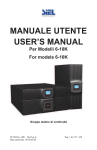
Master luminaire with LIGHTGATEplus Instruction manual Service manual www.trilux.de Instruction manual Contents 2-24 Page Introduction General functions 2 System luminaires and components 3 Function and operation Operating modes 4 Operation 5 One-button control 6-7 Multiple-button control 8 Overall room control 10-11 Individual control with two luminaire groups 12-13 Offset control with two luminaire groups and one sensor 14-17 Operation of up to 4 luminaire groups 18-20 Control without daylight-dependent operation 21-22 Operation of lighting system with radio remote control (LGR-SC) 23-24 1 Introduction General functions System luminaires and components LIGHTGATEplus can be configured individually to operate the luminaires to suit your needs or requirements. All connected luminaires (control gear units) must be equipped with a DALI interface (Digital Addressable Lighting Interface). Master luminaires Master luminaires are prewired ready for connection and equipped with an integrated controller and sensor. Additional sensors can be connected. All connections for the DALI interfaces and the operating keys are connected to easily accessible plug-in terminals. Daylight-dependent operation The daylight-dependent operation reduces the energy consumption of the lighting system. When there is daylight, the lighting is dimmed or even possibly switched off. With darkness falling, the dimmed lighting is automatically increased again. Uncontrolled operation If necessary, the daylight-dependent operation can be deactivated by manually dimming the lighting to a desired brightness. The intuitive one-button control with a deactivation button offers a convenient option in this regard. Presence detection In many cases, an additional energy savings can be achieved by means of presence detection. To this end, one or more presence sensors are used. The sensors are designed in such a way that they identify even slight movements (e.g. in an office). Light scenes The lighting system in a room can be divided in up to four separate luminaire groups with the aid of LIGHTGATEplus. These can be set to different levels of brightness. Such “light scenes” can be saved and then reactivated. We recommend using a radio remote control (e.g. LGR-SC) in many cases for programming and activating the light scenes. Controller luminaires The setup of the controller luminaires corresponds for the most part with the setup of the master luminaires, however, the sensor is to be mounted externally. As an alternative, a larger sensor (Sensor LGS-RPL/S) can be used, which also includes a radio receiver for a radio remote control and is characterised by an increased sensitivity in the presence detection functionality. Sensor luminaires Sensor luminaires are system luminaires that are equipped with a sensor and which can be used to expand the range of presence detection or for independent control of a second area (a second luminaire group). n o Ma t Au ID Radio remote control The LGS-RPL/S sensors additionally contain a radio receiver for the radio remote control LGR-SC. This provides additional control and programming functions. 1 2 3 4 O 2 3 Operating modes and control Operating modes Operation Daylight-dependent operation After being switched on the LIGHTGATEplus is usually in the daylight-dependent operating mode (controlled operation), the energy-saving mode of operation (provided a sensor is connected and the daylight-dependent control is not deactivated). Automatic operation With LIGHTGATEplus a lighting system can be operated fully automatically, without switches and push-buttons. Implementing daylightdependent operation and presence detection (automatic operation, see above) guarantees that there is always sufficient light available whenever it is needed. Uncontrolled operation The LIGHTGATEplus generally switches to uncontrolled operation when manual dimming is activated or when setting it to 100% operation or by activating a light scene. The uncontrolled operating state is indicated by the LED which is constantly illuminated in the sensor unit. The daylightdependent control remains deactivated until switched off (exception: 100% operation invoked with mains switch). After being switched back on, the control is active once more. Mains switch operation In many cases, a mains switch alone is sufficient as control element for a lighting system. The following switch functions are possible: 100% scene Presence detection The presence detection function is generally independent of the light controller. Here it is possible to choose between automatic operation and semi-automatic operation. The turn-off delay can be adjusted between on minute and sixty minutes or even deactivated when nobody is present, the lighting system is switched to standby operation). In semiautomatic operation, re-starting is deactivated. Standby In order to be able to operate the LIGHTGATEplus system using push-buttons, it must be set to standby operation. This results in a lower, but constant power consumption of the lighting system (Technical Specifications, see Service Manual, page 59). Off The mains switch can be used to disconnect the Lightgate Plus system from the power supply in order to prevent a slight energy usage due to standby losses. 4 Switch ON OFF OFF ON < 5 Sec. off OFF 100% 60 Min. - The switch can be used to turn the lighting on and off. -W hen switching the lighting system on, this generally starts up in the daylight-dependent operation mode. -A lighting system can be switched to uncontrolled operation with 100% luminous flux being produced by briefly switching it off and back on within five (5) seconds. - This operating mode is limited to 60 minutes. - During this time period, the presence detection function is deactivated. -O nce this period elapses, the system automatically switches back to daylightdependent operation. -T he daylight-dependent mode of operation can be reactivated at any time by switching the system off and back on at an interval of more than five (5) seconds. 5 One-button control The One-button control option provides more advance functions compared to the mains switch. This is envisaged for all applications of the LIGHTGATEplus System equipped with one, two, three or four luminaire groups. That includes push-button functions: - Switching on and off, - Dimming and brightening (group 1 and 2), and - Switching the lighting system between daylight-dependent operation and uncontrolled operation with 100% luminous flux. Push-button functions short Brief press of button Switch turning on/turning off the lighting system, when switching on, the lighting system is generally in daylight-dependent operating mode. Note: When operating in uncontrolled mode, the lighting system is switched off by means of a brief press of the press-button. When the lighting system is switched back on, it is generally in daylight-dependent operating mode. short off long long short short brighter double double long double Long press of button (hold) Dimming and brightening the light of the lighting system with a long press of the button. In this case, the daylight-dependent operation is deactivated. Note: Another long press of button reverses the dimming level. With light switched off (in standby), a long press of the button has no effect. off darker double Push-buttons (Group 1 and 2) short long short off short long double 100% Double-click; (pressing two times in a row quickly) Switch between daylight-dependent operation/uncontrolled operation with 100% by means of a double-click. Note: In case of uncontrolled operation with any dimming level, a double-click sets the lighting system to daylight-dependent operation. Another double-click returns the system to uncontrolled operating mode with 100% luminous flux in accordance with the main function. With light switched off (in standby), a double-click has no effect. 6 7 Multiple-button control If there is a need for additional operating functions, a multiple-button control with up to four push-buttons can be set up when connecting the luminaire. In doing so, the functions of the push-buttons are as follows: Push-button T1 (similar to one-button control) Schalter - Switching on/off with a short press of button - Dimming with a long press of button - Switching between daylight-dependent controlled/ uncontrolled operation with a doubleclick (for further information, see the following section on Application) Push-button T2 (when there is a second luminaire group) Schalter - Other on/off functions - Dimming and change-over functions (see „Individual control of two luminaire groups“ and „Offset control with two luminaire groups“) Push-button T3 (switch-off function) This function is used, e.g., for the central short deactivation of multiple lighting systems off in a building by the building superintendent. Push-button T4 (light scene activation) This function is used short short off to activate a preset light without daylight-dependent scene control. How to set a light scene is describedin the Service manual. Pressing a push-button switches the lighting system on while activating a light scene. Pressing the push-button again switches off the lighting system. With the lighting system operating (controlled or uncontrolled, apart from light scene) the press of a button also activates the light scene. (for further information, see the following section on Application) 8 9 Overall room control (control of one luminaire group) Multiple-button control (with up to 3 push-buttons, see page 8-9). In most applications, the overall lighting system is controlled as one luminaire group with one light sensor depending on the level of daylight. Push-button T1 (similar to one-button control) short short off long long short off Sensor brighter darker double double short off 100% Push-button T2 (without function) Push-button T3 (central deactivation) short off Push-button T4 (light scene) The following operating modes are possible: Automatic operation (see page 5) Mains switch operation (see page 5) short short scene off One-button control (see page 6) 10 11 Push-button T1 (group 1) Individual control of two luminaire groups In rooms where there are very different levels of daylight incidence, e.g. with considerable room depth, it is possible to set up two separately controlled luminaire groups. Two light sensors are needed for controlling the luminaire groups separately. The setpoints are set separately. The area controls dim and activate the lighting separately from one another. The presence detection extends over both areas. Push-button T2 (group 2) short short off long long short off Group 2 brighter darker double double short off Sensor 100% Sensor Group 1 -P ush-button T1 activates and dims only group 1 (functions like one-button control) -P ush-button T2 activates and dims only group 2 (functions like one-button control) Push-button T3 (central deactivation of group 1 + 2) The following operating modes are possible: Automatic operation (see page 5) short off Mains switch operation (see page 5) One-button control (see page 6) Note: With a long press of a button the dimming of both luminaire groups begins in the currently set dimming value. If the dimming level (brighter or dimmer) of both luminaire groups is different, the lighting system can be set to 100% operation by means of a double-click. From there, both luminaire groups are dimmed uniformly. (After turning off and back on, both groups start to operate at 100%) Multiple-button control (with up to 3 push-buttons, see page 8). 12 Push-button T4 light scene group 1 + 2) short short off scene - Push-button T3 switches off both luminaire groups (standby) -P ush-button T4 activates a light scene. The light values (uncontrolled) of both luminaire groups can be set separately (see Service Manual). 13 Offset control with two luminaire groups and one light sensor For the offset control the luminaires of the lighting system are divided into two group, close to window and far away from window, however controlled in relation to daylight with only one sensor. This operating mode can be used in rooms having an average room depth, where there is no need for a second sensor. In this case, group 1 (far away from window) is always controlled via the light sensor. Group 2 (close to window) is dimmed together with group 1. The difference (offset) between group 2 and group 1 is adjustable. With daylight increasing group 2 is dimmed to the minimum and remains there, until the group is switched off together with group 1 when there is sufficient daylight. When daylight decreases, the offset value is automatically reduced such that both groups of luminaires have the same dimming level without daylight. Preset by the function of the LIGHTGATEplus system, the group located away from the window must always be selected as „group 1“ and the group close to the window “group 2”. The following operating modes are possible: Automatic operation (see page 5) Mains switch operation (see page 5) One-button control (see page 6) Note: With a long press of a button both luminaire groups start to dim to the currently set dimming value. If the dimming level (brighter or dimmer) of both luminaire groups is different, the lighting system can be set to 100% operation by means of a double-click. From there, both luminaire groups can be dimmed uniformly. (After turning off and back on, both groups start to operate at 100%) short short off Group 2 long long short off darker Group 1 brighter Sensor double double short off 100% 14 15 Multiple-button control (with up to 4 push-buttons, see page 8). Push-button T1 short short off group 1+2 - Push-button T1 switches the lighting system on in daylight-dependent operating mode and off (standby). In addition, it dims and actuates group 1. group 1+2 long long short short short off group 1 brighter double group 1 off group 1 group 1+2 group 1+2 darker double short off 100% group 1 group 1+2 group 1+2 short short short off off group 1 Push-button T2 group 1+2 group 1+2 -Push-button T2 switches the lighting system on and dims/switches group 2 (group 1 cannot be switched off with T2). short short off group 1+2 group 2 long long short off group 2 brighter double group 2 group 2 darker double short off 100% group 2 group 1+2 group 2 Push-button T3 (central deactivation of group 1+2) short Push-button T4 (light scene group 1+2) short short off scene 16 off 17 Operation of up to 4 luminaire groups (addressing mode) With LIGHTGATEplus it is possible to arrange up to four luminaire groups with the aid of the DALI addressing function (see Service manual). - By doing so, groups 1 and 2 can be controlled in the daylightdependent operating mode. - Groups 3 and 4 are not included in the daylight-dependent operating mode. They serve as auxiliary luminaire groups. Their activation level can be pre-set (see Service Manual). - Groups 3 and 4 are generally switched on and off with group 1. - Switching off group 1 or 2 based on the daylight-dependent control has no impact on groups 3 and 4. - Groups 3 and 4 are actuated by means of the presence detection function. - Groups 3 and 4 can also be incorporated in programmable light scenes. Their light level can be preset for the light scene regardless of the activation level (see Service Manual). - A variable dimming of both luminaire groups is possible with the radio remote control. The addresses of all groups must not be assigned during the DALI addressing function. With regard to the daylight-dependent control of groups 1 and 2, all applications (overall room control, individual control of two groups, offset control) can be realised, and one or two auxiliary luminaire groups can be arranged. The following operating modes are possible: Automatic operation (see page 5) Mains switch operation (see page 5) By briefly switching off and back on, groups 3 and 4 do not switch to uncontrolled operating mode with 100%, but rather remain at their predefined activation level. One-button control (see page 6) The uncontrolled groups 3 and 4 are only actuated, not dimmed. Their activation level is predefined (see above). Group 2 Push-button Sensor short short off Group 1 Master Sensor Group 3 long long short off darker brighter double double short off 100% Group 4 Push-button 18 19 Control without daylight-dependent control function Multiple-button control The multiple-button control is as described in the preceding sections on the overall room control, individual control of two groups and offset control. -G roups 3 and 4 are actuated with group 1. Their-activation level is predefined (see above). -T heir light level that is called in the light scene with push-button 4 is independent of their activation level. Overall room control If a controller luminaire is operated without a sensor or the light sensor is deactivated, the lighting system can only be operated manually in the uncontrolled operating mode. One-button control (only manual): Push-button short Note: Groups 3 and 4 can be dimmed and actuated separately using a system radio remote control. short off 100% long long short off darker brighter Long press of a push-button does not switch the lighting system on. Double-click has no effect. Multiple-button control (only manual): The functions of push-button T1 are identical to the one-button control (see above). Push-button T2 has no function. The functions of push-buttons T3 and T4 are identical to control operating mode (see page 8). Two-group control Both luminaire groups are controlled manually as with the one-button control, however individually with the aid of separate push-button T1 and push-button T2. An operation of two luminaire groups without daylight-dependent control with a common push-button is not envisaged with the LIGHTGATEplus system. 20 21 Three and four-group control (only manual) With regard to DALI connection of a lighting system with the DALI groups 3 and 4, the assigned luminaires generally behave as follows: - The luminaires of groups 3 and 4 are switched with the aid of the push-button T1 with group 1 based on the pre-set activation value (see Service Manual). - Luminaires of the DALI groups 3 and 4 are not dimmed at the same time. - Push-button T2 does not have an effect on groups 3 and 4. - Push-button T3 switches the groups 3 and 4 off at the same time. - Groups 3 and 4 are taken into consideration when activating the light scene with the aid of push-button T4. Their dimming values can be pre-set without regard given to the activation values that are called with push-button T1(see Service manual). Operation of lighting system with radio remote control The radio remote control LGR-SC is used for the convenient activation of a lighting system with LIGHTGATEplus. There are extensive operating options available for all four possible luminaire groups. In addition, the radio remote control LGR-SC can be used for programming the system (addressing, set-point adjustment, etc. ...). Information in this regard can be taken from the separate instruction manual of the radio remote control LGR-SC (170 742–10 /2006 © BAG electronics GmbH) . For using the radio remote control LGR-SC ma sensor of the LGSRPL/S design must be present (for recess and surface-mounting on ceilings). A radio receiver is integrated in it. No direct visual contact is necessary between radio remote control LGR-SC and sensor. Note though that the range of transmission can be negatively affected by metal ceilings or other solid structures. Before the radio remote control LGR-SC can be used, an addressing can be implemented. Front view Rear view 2 Auto Man 1 4 3 ID O 78 23 9 01 456 Rotary switch In order to be able to use the radio remote control LGR-SC, the rotary switch must be set in the radio remote control function to the “0” operating mode (see Instruction Manual 170 742 – 10 /2006 © BAG electronics GmbH). 22 23 With this switch, it is possible to call the following functions. • Switching the lighting system on and off in daylightdependent operation • Switching between daylight-dependent and uncontrolled operation • Dimming of the entire lighting system When actuating a dimming button of the remote control, all set-up luminaire groups are always addressed (even groups 3 and 4, other than during the one-button control). • Dimming of individual luminaire groups (even Group 3 and 4) • Calling up to four set-points for the daylight-dependent operation • Calling up to four light levels for the uncontrolled operation • Calling up to four light scenes with up to four luminaire groups. For more information see the Instruction Manual for Radio remote control LGR-SC 170 742 – 10 /2006 © BAG electronics GmbH. 24 25 Service manual 27-60 Contents Page Safety and installation suggestions 28 Start-up - Control of one luminaire group (overall room control) - Individual control of two luminaire groups (two individually controlled luminaire groups) 29-31 - Offset control with two luminaire groups and one sensor (second luminaire group controlled independently) 36-39 - Operation of up to four luminaire groups (with the aid of DALI addressing) 40-43 32-35 System characteristics 26 - General functions 44-45 - DALI connection 46-48 - Master luminaires, controller luminaires and sensor luminaires 49-51 - Sensor functions 51-52 - Daylight-dependent control 53 - Presence detection 54-58 Other system components 57-59 Technical specifications 60 27 Safety and installation instructions • Implementing the service manual requires specific technical knowhow that is equivalent to completed vocational training as an electrician!• Never perform work with the luminaire connected to a power source. Caution - Danger to Life! Use Control of one luminaire group (Overall room control, broadcast operation, see page 46-47). In most applications, the overall lighting system is controlled as one luminaire group with one light sensor depending on the level of daylight. D2 D1+ 28 5 6 7 8 1 2 3 4 L N D2 D1+ L N Sensor Controller/DALI-EVG L N D2 D1+ DALI-EVG D2 D1+ L N DALI-EVG DALI-EVG N L L N DALI-EVG D2 D1+ L N DALI-EVG • Observe the installation instructions the luminaires that are imple mented. 29 DALI connection It is possible to actuate up to 50 luminaires (and/or 50 control gear units). While doing so, it is not necessary to remove the DALI bridge of the master luminaire (condition as supplied to customer, see page 46-48). A DALI addressing is not necessary. Note: - All control gear units must be unaddressed (see page 47) - For positioning the master luminaire and/or the light sensor (see page 53). Setpoint adjustment with push-button T1 Set selector switch A to (Unlock programming by means of push-button, only when using the sensor LGS-RPL/S) Lighting off Standby, with push-button T1) 1 2 1 2 Push-button connection If necessary, the push-buttons are to be connected in accordance with the desired functions (see Instruction Manual) (see Wiring Diagram, page 44-45) Schalter + ON Presence detection Mains voltage is necessary to set the presence detection unit (see page 54-56). Min/ON/Min/ON/Min long double long 10 Sec. Initiating the programming mode (push-button T1) System ready LED blinkts quickly Save Adjust setpoint Done Setpoint adjustment The setpoint can be adjusted either with the aid of the sensor‘s programme functions (see page 30-31) or with the push-buttons. - Setpoint adjustment with sensor LGS-OPL/M (mini sensor, integrated in luminaire) LED blinks Setting light level with push-button 4 (only for multiple-button control, see page 8) long Gr.1 Gr.1 brighter 1 Sec. Initiating the setpoint programming (hold push-button of group 1) long Gr.2 darker 10 Sec. No change LED blinks quickly Done Adjust setpoint Set selector switch A to (Unlock programming by means of push-button,only when using the sensor LGS-RPL/S) Lighting off (Standby, with pushbutton T1) 1 2 - Setpoint adjustment with sensor LGS-RPL/S (recessed and surface-mounted ceiling sensor) Switch on the lighting system (controlled, LED off) 1 Activading the setpoint adjustment (selector switch A to 1) 30 - Adjustment Schalter with push-button T4 LED blinks quickly + Adjust setpoint (several turns) 20 Sec. No change Done ON Min/ON/Min/ON/Min System ready 2 + long long 10 Sec. Initiating the programming mode (hold push-button T4) 1 Set light scene double Save LED blinks quickliy Done 31 Individual control of two luminaire groups (broadcast operation, see page 47) N L DALI-EVG L N Sensor 1 5 6 7 8 1 2 3 4 L N Controller/DALI-EVG DALI connection Up to 25 luminaires (and/or 25 control gear units) can be controlled per Dali connection. While doing so, the DALI bridge of the master luminaire must be removed. A DALI addressing is not necessary. As an alternative, all luminaires can be connected to a common control line and a DALI addressing can be implemented (see page 46-48). Note: For positioning the master luminaire and/or the light sensor (see page 54). D2 D1+ Push-button-connection If necessary, the push-buttons are to be connected in accordance with the desired functions (see Instruction Manual) (see Wiring Diagram, page 44-45). Sensor addressing Every sensor, external or in a master or sensor luminaire, is set to the sensor address 1 when supplied to the customer. The sensor in the sensor luminaire must be switched to sensor address 2 (see page 49-52). Presence detection Mains voltage is necessary to set the presence detection system (see page 54-55). D2 D1+ L N DALI-EVG L N D2 D1+ L N DALI-EVG 32 D2 D1+ DALI-EVG Group 1 L N DALI-EVG D2 D1+ Sensor 2 Group 2 In rooms where there are very different levels of daylight incidence, e.g. with considerable room depth, it is possible to set up two separately controlled luminaire groups. Two light sensors are needed for controlling the luminaire groups separately. The setpoints are set separately. The area controls dim the lighting independently from one another. The daylight-dependent shut-off is implemented when there is sufficient daylight available in the area of group 1 (see page 52). The presence detection extends over both areas. Setpoint adjustment The setpoint can be adjusted either with the aid of the sensor‘s programme functions or with the push-buttons.. 33 - Setpoint adjustment with sensor LGS-OPL/M (mini sensor, integrated in luminaire) Switch on the lighting system (controlled, LED off) Adjust the setpoint for group 1+2 as follows: LED blinks long Gr.1 Gr.1 brighter 1 Sec. long Initiatingthe setpoint programming (hold Gr. push button of group 1) Gr.2 darker 10 Sec. No change LED blinks quickly - Setpoint adjustment with push-button T1 Set selector switch A to (Unlock programming by means of push-button, only when using the sensor LGS-RPL/S) Lighting off (Standby, with push-button T1) Schalter Done ON Adjust setpoint 10 Sec. Change the setpoint for group 2 as follows: LED blinks long Gr.1 Gr.2 brighter 1 Sec. long Initiating the setpoint programming (hold push-button of group 2)) 10 Sec. No change Gr.2 darker Min/ON/Min/ON/Min LED blinks quickly Initiating the programming mode System ready (hold push-button T1) (group 1+ group 2) Min/ON/Min/ON/Min long long Adjust setpoint (Gr. 1) long long double Save double System ready (group 2) Set offset value (group 1+2) Save - Setpoint adjustment with sensor LGS-RPL/S (recessed and surface-mounted ceiling sensor) Setting light level with push-button 4 (only for multiple-button control, see page 8) Set selector switch A to (Unlock programming by means of push-button, only when using the sensor LGS-RPL/S) Lighting off (Standby, with push-button T1) Switch on the lighting system (controlled, LED off) Adjust setpoint with potentiometer for group 1 as follows: + Activating the setpoint adjustment (selector switch A to 1 ) Schalter blinks quickly Activating the setpoint adjustment (selector switch A to 2 ) Done Adjust setpoint (group 1) Adjust setpoint with potentiometer for group 2 as follows: 2 LED blinks quickly Done Adjust setpoint 1 LED blinks quickly + Adjust setpoint (group 2) 20 Sec. No change T4, similar to adjusting the setpoint with push-button T1 Done Note: The setpoint for both luminaire groups can be adjusted at a sensor (sensor 1 or 2). 34 35 Offset control with two luminaire groups and one light sensor, (broadcast operation, see page 47) D2 D1+ Note: Group 1 is the „master group“ in the case of offset control with two luminaire groups. Group 2 is updated, in relation to group 1. In case of the multiple-button control, particular attention must be given to: The actuation of push-buttons T1 and T2 can have repercussions on the operation of both groups depending on the current operating status. On an individual case basis, it is necessary to determine whether preference is to be given to an overall room control or an individual control with two light sensors of offset control. 5 6 7 8 1 2 3 4 Note: For positioning the master luminaire and/or the light sensor (see page 53). As an alternative, all luminaires can be connected to a common control line and a DALI addressing can be implemented, see page 46-49. L N Controller/DALI-EVG With daylight increasing, group 2 is dimmed to the minimum and remains there, until the group is switched off together with group 1 when there is sufficient daylight. When daylight decreases, the offset value is automatically reduced such that both groups of luminaires have the same dimming level without daylight. Preset by the function of the LIGHTGATEplus system, the group located away from the window must always be selected as „group 1“ and the group close to the window „group 2“. DALI connection Up to 25 luminaires (and/or 25 control gear units) can be actuated per Dali connection. While doing so, the DALI bridge of the master luminaire must be removed. A DALI addressing is not necessary. D2 D1+ L N D2 D1+ DALI-EVG sensor L N D2 D1+ L N DALI-EVG DALI-EVG N L L N DALI-EVG Group 1 D2 D1+ L N DALI-EVG Group 2 For the offset control the luminaires of the lighting system are divided into two groups, close to window (window) and far away from window (corridor), however controlled in relation to daylight with only one sensor. This operating mode can be used in rooms having an average room depth, where there is no need for a second sensor. In this case, group 1 (far away from window) is always controlled via the light sensor. Group 2 (close to window) is dimmed together with group 1. Push-button connection If necessary, the push-buttons are to be connected in accordance with the desired functions (see Instruction Manual) (see Wiring Diagram, page 44-45). Sensor addressing Every sensor, external or in a master or sensor luminaire, is set to the sensor address 1, when supplied to the customer (see page 48). With daylight, less artificial light is required in the area of group 2 (close to window). That‘s why, this group can be operated with reduced wattage. The difference (offset) between group 2 and group 1 is adjustable. 36 Presence detection Mains voltage is necessary to set the presence detection unit (see page 54-56). 37 Setpoint adjustment The setpoint and the offset value can be adjusted either with the aid of the programme functions of the sensor (see page 30-31) or with push-button. - Setpoint adjustment with sensor LGS-OPL/M (mini sensor, integrated in luminaire) Switch on the lighting system (controlled, LED off) Adjust the setpoint for group 1 as follows: LED blinks long Gr.1 Gr.1 10 Sec. brighter 1 Sec. Initiating the setpoint programming (hold push-button of group 1) long No change Gr.2 darker ON Done 10 Sec. Aufruf des Programmiermodus (Taster T1 halten) long Gr.1 Gr.2 brighter 1 Sec. long Initiating the offset prigranning (hold push-button Gr. 2) System bereit* (Gr. 1+2) 10 Sec. No change Gr.2 darker Done - Setpoint adjustment with sensor LGS-RPL/S (recessed and surface-mounted ceiling sensor) Switch on the lighting system (controlled, LED off) Adjust the setpoint for group 1 with potentiometer as follows: 1 Adjust setpoint (group 1 + group 2) Adjust the offset value for group 2 with potentiometer as follows: 2 long Sollwert einstellen (Gr. 1) long long System bereit * Offsetwert einstellen (Gr. 2) (Gr. 2) double LED blinkt schnell speichern double speichern LED blinkt schnell fertig * Only the luminaires of the respective group that is to be set respond Note: The lighting system can be set only lower for group 2 but not higher than for group 1 (negative offset). Programming a light scene (only with multiple-button control) A light scene can be programmed with the aid of the push-button T4, with which it can be activated. Set selector switch A to (Unlock programming by means of push-button, only when using the sensor LGS-RPL/S) Lighting off (Standby, with push-button T1) LED blinks quickly Activating the offset value adjustment (selector switch A to 2 ) long Setting light level with push-button 4 (only for multiple-button control, see page 8) + Activating the setpoint adjustment (selector switch A to 1) Min/ON/Min/ON/Min LED blinks quickly Set offset value 38 Min/ON/Min/ON/Min Change the offset value for group 2 as follows: LED blinks Schalter LED blinks quickly Adjust setpoint - Setpoint adjustment with push-button T1 Set selector switch A to __ (Unlock programming by means of push-button,only when using the sensor LGS-RPL/S) Lighting off (standby, with push-button T1) + Set offset (Gr.2) 20 Sec. No change Done Schalter Push-button T4, like adjusting the setpoint with push-button T1 39 Operation of up to 4 luminaire groups Addressing mode DA DA DA DA L N DALI-EVG Note: If control gear units are to be used, for which a DALI group address is already programmed, the DALI addressing can be deleted (see page 45). - A DALI addressing can be implemented with the daylight-dependent control of two groups. It is possible to forego if the groups can be connected to separate control lines (see page 32 und page 36). - I n case of daylight-dependent control of one or two luminaire groups (group 1 + 2) with the operation of additional groups without daylight-dependent control (group 3 + 4), a DALI group addressing is necessary. DALI connection Up to 50 luminaires (and/or 50 control gear units) can be controlled. While doing so, the DALI bridge of the master luminaire must not be removed (condition as supplied to customer). L N DALI-EVG DA DA When there is only one group to be controlled, it is possible to do without addressing (see page 44-48, Control of a luminaire group). Sensor 1 5 6 7 8 1 2 3 4 Push-button connection If necessary, the push-buttons are to be connected in accordance with the desired functions (see Instruction Manual) (see Wiring Diagram, page 44-45). L N DA DA L N Controller/DALI-EVG Note: For positioning the master luminaire and/or the light sensor (see page 52). DALI-EVG DALI-EVG L N DA DA L N DALI-EVG DA DA Group 1 L N DALI-EVG DA DA Sensor 2 Group 2 N L DALI-EVG L N Group 3 N L With LIGHTGATEplus it is possible to create up to 4 luminaire groups with up to 50 luminaires (and/or control gear units) in total. In doing so, the groups 1 and 2 can be controlled in relation to the daylight. The grouping can be implemented by assigning the DALI group addresses (group 1 to 4) to all luminaires (and/or control gear units), which are connected to a common control line. Sensor addressing Every sensor, external or in a master or sensor luminaire, is set to the sensor address 1 when supplied to the customer. If multiple (up to 3) sensors are used, these must have different addresses (see page 44). Presence detection Mains voltage is necessary to set the presence detection system (see page 54-56). 40 41 DALI group addressing The DALI group is addressed with the aid of the push-button T1 or the system remote control. The addressing process with the aid of remote control is described in the related instruction manual (170 742 – 10 /2006 © BAG electronics GmbH). The addressing process by means of push-button is implemented in three steps: - Step 1 Activation of the programming mode - Step 2A control gear unit is indicated, which is not assigned a group address, in order to be able to assign it. This is repeated until all control gear units have a group address. - Step 3To facilitate monitoring, all control gear units show their group addresses successively. Each address can be confirmed or cor rected. If no correction or confirmation is made in 30 seconds, the address is accepted as correct and the next control gear unit is called. In the end, the system is switched to 100% operation. DALI group addressing with push-button T1 Switch on lighting Set selector switch A to only when using the sensor LGS-RPL/S (unlock programming with push-button) Lighting off (with push-button T1) 2 Step 3 (check/change *) All luminaires blink 3x (all luminaires are addressed) Next luminire blinks (e.g. 1 x for group 1) Addressing of group 1-4 (press 1x-4x) One luminaire blinks (e.g. 2 x for group 2) Addressing of group 1-4 (press1x-4x) Last luminaire blinks Addressing of group 1-4 (e.g. x for group 3) (press 1x-4x) * With 1-4 presses of the push-button, the group addressing 100% of each luminaire can be confirmed or changed. Addressing If no push-button is pressed in 30 seconds, the next lumicomplete naire shows its group assignment (by blinking 1x to 4x). The DALI addressing can be ended at any time by pressing 5 Sec. and holding the push-button for about 5 seconds. In such case, all addressing actions implemented until then will End stored. addressing 1 1 10 x The DALI addressing of all luminaires can be deletedat any time by pressing the push-button ten times. Delete addressing 2 Schalter If group addresses are already assigned for all control gear units, step 2 can be skipped. When adding an additional control gear unit, an address will only be assigned to this unit. For operation with the aid of the remote control, see instruction manual Radio remote control LGR-SC 170 742 – 10 /2006 © BAG electronics GmbH. - Step 1 + 10 Sec./ON 5 Sec./Min. 5 Sec./100% Initiating the programmingmode (hold push-button T1) System ready Step 2 One luminaire blinks Adressing Next luminaire of group 1- 4 blinks (press 1x - 4x) Adressing complete Adressing of group 1- 4 (press 1x - 4x) 42 Last luminaire blinks Setting setpoints, offset and light scenes The setpoints and offset values and light scenes are set as described on pages 34-35, 38-39 and 40-41. When adjusting the light scene with push-button 4, additional light scenes can be assigned for groups 3 and 4. Adressing of group 1- 4 (press 1x - 4x) 43 System characteristics General functions All connected luminaires (control gear units) must be equipped with a DALI interface (Digital Addressable Lighting Interface). New lamps must be burned in with 100 hours at 100% operation, before they may be operated as a dimmed setting. The control functions for different systems, applications and operating modes are described in the instruction manual. LIGHTGATEplus can be operated with up to four luminaire groups and with up to four push-buttons. LIGHTGATEplus master and control luminaires are to be operated principally as a local, closed lighting management system. Operating several master or control luminaires in one comprehensive lighting system is not allowed. Operating DALI control gears (DALI electronic control gears) at the same time on several parallel DALI control devices is not permitted according to IEC 62386. Factory setting of a master/controller luminaire: - DALI bridge set: one luminaire group, broadcast operation, up to 50 control gear units - Push-button bridge set: One-button control - With DALI bridge set: Assignment of up to four luminaire groups possible by means of DALI addressing. Other connection options: - Remove DALI bridge: connection of luminaire group 1 and 2, broadcast operation, each 25 control gear units. - Remove push-button bridge: Multiple-button operation, up to four push-buttons can be connected. EVG N L max. 24 EVGs 1 2 3 4 5 6 7 8 T1 T2 T3 T4 max. 25 EVGs EVG N max. 49 EVGs 44 L 1 2 3 4 5 6 7 8 T1 Note: -T he DALI control lines must be designed such that they are rated for mains voltage. They may be implemented with supply voltage in a common sheathed cable. -T he connecting cables of the push-buttons are to be implemented separately 45 DALI connection The LIGHTGATEplus light management system uses the international standardised digital DALI protocol (Digital Addressable Lighting Interface) to actuate the lighting system. The luminaires that are to be actuated must be equipped with dimmable electronic control gear that includes a DALI-compliant interface. The DALI control lines must be designed such that they are rated for mains voltage. They may be implemented with supply voltage in a common sheathed cable. It is not necessary to pay attention to the polarity of the interface connection. When switching off the lighting system via the DALI interface, the controller and control gear units remain connected to the power source so that they are ready for operation. To minimise power consumption in standby mode, it is recommended a mains switch should be used as main control element in several applications and the entire lighting system should be disconnected from the power source when not in use. All implemented system settings remain unchanged. Switching on the power supply results in the lighting system operating in the energysaving, daylight-dependent controlled mode. It is possible to change over to the uncontrolled 100% operation at any time (see page 5). As an alternative to the mains switch, the standby output of the control gear units can be eliminated by a LIGHTGATEplus system relay (see page 57-58). The system offers two possibilities for controlling DALI-compliant electronic control gear: Fig. 1 EVG N L 1 2 3 4 max. 24 EVGs max. 25 EVGs Fig. 2 EVG N max. 49 EVGs 46 L 1 2 3 4 Broadcast operation In this operating mode it is not necessary to address individual DALI electronic control gear units. It is possible to distinguish between a maximum two groups . For the distinction between two luminaire groups, these are connected with separate control lines at the luminaire terminals 1 and 2, or 3 and 4, of both DALI interfaces (The DALI bridge is to be removed for this purpose, Fig. 1). Each group may comprise no more than 25 DALI electronic control gear units. Already assigned DALI addresses of individual control gear units shall not be taken into account. If only one luminaire group should be set up, it is possible to operate up to 50 control gear units on a common two-wire control line (Fig. 2). The DALI bridge remains set (condition as supplied to customer). For the broadcast operating mode, none of the control gear units may be assigned a DALI group address (LIGHTGATEplus controls in the addressing operating mode, see below). If possible, DALI group addresses that are already assigned can be deleted (see page 43). Addressing mode For this operating mode, all control gear units can be connected with a common control line (Fig. 2). To distinguish between up to four groups an addressing (DALI group addressing) of the individual DALI control gear units is necessary. On the whole the DALI control circuit may consist of a maximum 50 DALI electronic control gear units. When setting up the groups, it is necessary to note that daylight-dependent control is only possible for the groups with the addresses 1 and 2. The individual operational features and functions can be taken from the sections of the instruction manual. Push-button connection A bridge between the terminals 6 and 8 is used in the state the master and/or controller luminaires supplied to the customer. The LIGHTGATEplus controller is in the operating state of a one-button control. By removing the bridge, it is possible to switch to the multiple-button control operating mode. The push-button functions are described in the relevant sections of instruction manual. The push-buttons‘ connecting cables are to be routed separately from the mains supply cables. In case of parallel routing (e.g. in a common empty conduit) use a twisted or shielded push-button cable. Connecting several, parallel normally open buttons (several control sections) is possible within the limits of the permissible line lengths. Connecting several master and control luminaires (control devices) to a common button is not permissible for T1, T2 or T4. It is permitted to have a common switching off of the LIGHTGATEplus systems by means of a common connection T3. The technical specifications for the push-button connections can be taken from the table below on page 60. 47 Sensor connection SemiAUTO AUTO Master luminaires (with integrated controller and sensor) Gr.1 The sensor LGS-OP/M of the master luminaire is addressed to the sensor address 1 in the state delivered to the customer. 0 5 5 15 15 30 30 LIGHTGATEplus master luminaires are equipped with a pre-connected sensor unit that is already integrated in the luminaire. If necessary, additional sensors can be connected with the master luminaire with the aid of a free RJ11 connection (see fig.). Master luminaires, controller luminaires and sensor luminaires Gr.2 Master luminaire + max. 2 x sensor LGS-RPL/S Test - Sensor LGS-OPL/M (mini sensor, integrated in luminaire) Controller The sensor units are connected to a controller luminaire in the same manner. A maximum three sensor units can be connected in parallel using a two-way splitter 0MD2. In doing so, particular attention must be given to ensuring the correct addressing of the sensors, as described in the section on sensor settings. The technical specifications of the sensor connections can be taken from the table below on page 60. Addressing is implemented with the aid of the DIP buttons on the back of the sensor (for more information, refer to page 49-50). ON 1 2 Master luminaire + max. 3 x sensor LGS-RPL/S Setting the setpoints is a simple process thanks to the programme push-buttons available on the sensor. Controller Opening the light sensor Gr.1 SemiAUTO 0 Gr.1 AUTO 5 5 15 15 30 (an auxiliary tool for settings on the programme push-button is included with the master luminaire) 30 Programme push-button Gr.2 Test LED Selector switch for presence detection Presence detection The presence detection function can be deactivated on the sensor‘s selector switch or set to a shut-off delay between 3 minutes and 60 minutes. A distinction can be made between automatic operationON (with re-start) and semi-automatic operation (without re-start) (see page 1 2 54-55). 48 49 Controller luminaires (with integrated controller) Mount the sensor LGS-RPL/S externally when using controller luminaires. - Sensor LGS-RPL/S (external sensor) Presence detection The presence detection function can be deactivated on the sensor‘s selector switch or set to a shut-off delay between 3 minutes and 60 minutes. A distinction can be made between automatic operation (with re-start) and semi-automatic operation (without re-start) (see page 54-55). In the state delivered to customers, sensors LGS-RPL/S are addressed to sensor address 1 using DIP buttons (see page 48-51). LGS-RPL/S 8 9 AB Sensor Function + lx 6 34 5 7 2 F 0 12 CD E Order no. 169622 T-OFF Poti-Pos. Test 8 Off 0 3 Min. 1 F 5 Min. 2 E 10 Min. 3 D 15 Min. 4 C 20 Min. 5 B 30 Min. 6 A 60 Min. 7 9 AUTO SEMI-AUTO 1 – Sensor luminaires (with integrated sensor) Sensor luminaires include one sensor LGS-OPL/M. The sensor address is to be set in any case according to the desired function! The factory setting is sensor address 1 (see page 49-50). They are used to extend the range of the presence detection or for independent control of a second area. Sensor 1 Sensor 1 Sensor 2 Sensor 2 Presence detection The presence detection function can be deactivated on the sensor‘s selector switch or set to a shut-off delay between 3 minutes and 60 minutes. A distinction can be made between automatic operation (with re-start) and semi-automatic operation (without re-start) (see page 54-55). Setting the setpoints is a simple process thanks to the potentiometers available on the sensor. 1 Integrated sensor-LED Opening of the light sensor Group selector switch (A) 1 2 - - Potentiometer (B) 50 2 + + Sensor functions Sensor units of the LIGHTGATEplus system fulfill the tasks of light measurement and presence detection. Several settings of these functions are to be implemented directly on the sensor. The adjustment of the setpoints or offset values of the daylight-dependent control can be taken from the first section of this service manual. Sensor assignment The sensor can be addressed using the two DIP switches (E) and the sensor‘s light measurement deactivated or activated and assigned to one of the luminaire groups 1 and 2. Each of the four possible switch settings corresponds to an individual sensor address. 51 Daylight-dependent control Note that all preset addresses are different in a lighting system with multiple sensors in order to ensure that the system does not malfunction. The table shows the possible DIP switch settings so that the sensor works as light sensor + presence detector or exclusively as presence detector, e.g. to extend the range of detection. DIP-switches Sensor Address Sensor function ON Position 1 2 Gr. 2 CD E F 0 12 Sensor 1 LGS-RPL/S Sensor 2 Order no. 169622 Sensor 1 Sensor Function Sensor 2 T-OFF Poti-Pos. Test 8 Off 0 3 Min. 1 F 5 Min. 2 E 10 Min. 3 D 15 Min. 4 C 20 Min. 5 B 30 Min. 6 A 60 Min. 7 9 AUTO SEMI-AUTO 3 8 9 AB Gr. 1 6 34 5 7 1 2 4 Daylight-dependent overall room/offset control Sensor address Sensor address 1 3 Sensoradress 4 Daylight-dependent individual group control Sensor address Sensor address 1 2 Sensor address 3 For applications with daylight-dependent overall room/offset control and the daylight-dependent control of individual groups, the possible DIP switch settings are directly indicated for the maximum permissible three sensors. 52 How daylight-dependent control works The light meter, which is integrated in the sensor, evaluates the brightness of an area under the sensor. The sensor‘s aperture for light measurement is approx. 20°. The brightness of the evaluated area is based on the reflections of the mixed light comprising artificial light and daylight. The resulting measured value is compared with the setpoint programmed by the user. In case of a difference between the measured value and setpoint, the artificial light is adjusted accordingly in such a way that the level of illumination practically remains constant. If the daylight is sufficient to surpass the setpoint, the artificial light is then switched off. In order to prevent disturbing fluctuations of the artificial lighting due to short-term changes in daylight (e.g. gaps in clouds), the dimming and switching functions are delayed; the artificial light is switched off, once the setpoint for the level of illumination is exceeded by approx. 25 % and if this condition lasts for 15 minutes. The lighting system is switched back on immediately, once daylight falls below the setpoint (only in the automatic operation of the presence detection). Grouping For daylight-dependent control of a lighting system it is necessary to note that only luminaires of group 1 and group 2 are available for this function. The DALI control gear units to group 1 and/or group 2 are assigned either in the broadcast operation (see page 48-49) directly by the routing of two separate DALI control lines or in addressing operation with the common control line by assigning DALI group addresses to the control gear units. If the addresses group 3 and group 4 are assigned in eh addressing mode, these are not integrated in the daylight-dependent control. Positioning of light sensors In general, the light sensors can be positioned such that they acquire the relevant area to be illuminated as much as possible. Make sure that they are not located over a completely dark, diffusely reflective surface that allows for a comparison between the actual value and the setpoint. In case of lighting systems with individual control of two luminaire groups, it is also necessary to make sure that the sensor is located respectively in the area of the luminaires of the group that are controlled by it. An unfavourable positioning may result in mutual interference of the control groups and thus in a limited control function. In case of offset control, the sensor is to be attached in a work area in the depth of the room, in the area of the luminaire group 1 that is far from the window. 53 Presence detection How presence detection works Presence detection system is based on a passive infrared sensor, which identifies changes in the thermal radiation in the area of coverage, when a person is moving, for instance. When positioning the sensor, care must be taken that there are no shadows in the area of coverage and thus the functionality of the sensor is not limited. Particular attention must also be given to the fact that air currents that are generated by other heat sources than people may result in malfunctioning, e.g. fax machines, heater fans and opened windows. Area of coverage The presence detection function of the sensor LGS-RPL/S is optimised for mounting on a ceiling at a height of 2.7 m (e.g. for office applications). The area of coverage has a diameter of 8 meters. While installing the presence detector on higher ceilings increases the area of coverage, it also decreases sensitivity. The maximum installation height of 8 m should not be exceeded, however. Depending on the intended use of space, the area of coverage can be extended additionally in many applications, for instance, in sports halls, by connecting presence detection sensors in parallel. Sensor LGS-RPL/S 1900 2700 8000 5000 Sensors of design LGS-OPL/M are designed for the recessed and surface mounting of luminaires. In case of a surface-mounted luminaire, the diameter of its area of coverage is approx. 5m at a height of 2.7m. 5000 3500 54 1900 2700 Sensor LGS-OPL/M Adjusting presence detection The turn-off delay is selected with the aid of a rotary switch for both sensor designs (front LGS-0PL/M, or back LGS-RPL/S). The presence detection must be adjusted with the system‘s power supply switched on! In case of systems with multiple sensors, the adjustment can be implemented optionally at each of the sensors. The system setting always corresponds to the setting implemented on one of the sensors with the power supply switched on. The position of the selector switch of the other sensors is irrelevant. The operating mode of the presence detection is also set in this manner. It is necessary to distinguish between the following operating modes: - Automatic operation The lighting system is automatically switched off, if no person is detected for a preset period of time. The lighting system is also switched on automatically when movement is detected, provided that the available daylight is insufficient. Switching on and off applies to all luminaire groups. Note: After switching off with the push-button, the automatic reactivation is active, after no person was detected at least for the preset time period (continuously). - Semi-automatic operation: The lighting system is automatically switched off, if no person is detected for a preset period of time. The switching off affects all groups of luminaires. In this mode, there is no automatic activation when movement is detected, but rather the lighting system must be switched on manually. In case of sufficient daylight, the lighting is dimmed accordingly and is switched off again when the daylightdependent shut-down criterion has been attained. Note: An automatic activation and/or reactivation of the lighting system, even after the lighting system is switched off by the daylight-dependent control, is generally implemented only when the presence detection is in the automatic operating mode. - OFF mode When switched to the „OFF“ position, the presence detection feature can be fully deactivated. In other words, the lighting system is not switched on or off automatically whenever a person enters or exits the area of coverage. 55 -TEST mode The test function is initiated for the presence detector when the rotary switch is set to the „TEST“ position. In this mode, the lighting system is automatically dimmed to the minimum setting, if no movement has been detected for a period of ten seconds. In case a person is detected subsequently, the light is brought up to 100 % again. If no movement is detected for another 10 seconds after dimming, the lighting system is switched off. As soon as the presence detector senses a movement, the system is automatically switched on again. During the TEST mode, an LED built-in the sensor will also blink if a person has been detected. The test function allows the user to check the sensitivity and range of the sensor. Note: If multiple sensors are connected to a controller, the settings implemented at one sensor are assumed for the entire system. To change a setting, the system‘s power supply must be switched on. After the rotary switch was turned to the desired position, the sensor LED blinks briefly several times in all connected sensors as confirmation. Selector switch Gr.1 LIGHTGATEplus system relay LGI-SA Many master and controller luminaires can be equipped upon request (custom production) with integrated system relay LGI-SA. The integrated controller is directly connected with the luminaire‘s power supply terminals. The relay actuates the integrated electronic control gear and the separate power supply terminals of the downstream DALI luminaires. Connection LGI-SA Broadcast operation: Controller AUTO 5 5 N 15 15 AUTO LGR-SC radio remote control The system remote control offers additional control options, convenient programming of all system settings and possibly the DALI addressing, as described in the associated instruction manual (170 742 - 10 /2006 © BAG electronics GmbH). LGI-SA EVG 0 30 30 SemiAUTO SemiAUTO Other system components L L’ 1 2 3 4 0 Gr.2 5 5 Test 15 15 30 30 LGS-RPL/S C DE 8 9 AB 89 A B 56 F 0 12 6 34 5 7 6 34 5 7 T-OFF Poti-Pos. Test 8 Off 0 3 Min. 1 F 5 Min. 2 E 10 Min. 3 D 15 Min. 4 C 20 Min. 5 B 30 Min. 6 A 60 Min. 7 9 AUTO SEMI-AUTO T-OFF Poti-Pos. Test 8 Off 0 3 Min. 1 F 5 Min. 2 E 10 Min. 3 D 15 Min. 4 C 20 Min. 5 B 30 Min. 6 A 60 Min. 7 9 AUTO SEMI-AUTO CD E Order no. 169622 F 01 2 Sensor Function Sensor 1 Sensor 1 Sensor 2 Sensor 2 For more information, see the data sheet for the LIGHTGATEplus System Relay LGI-SA, TOC 50 566 00. Notes: - The DALI bridge is not used (condition as supplied to customer) -T he phase L´ actuates with the OFF function of group 1. A sole operation of group 2 (without group 1) is not possible on L´ (condition as supplied to customer). -T he use of the DALI bridge leads to addressing operation (see page 46-47). -T he relay LGI-SA is then addressed to the DALI group 3 (condition as supplied to customer). -O ther relays LGI-SA can be connected to the DALI lines outside the luminaires (altogether max. 4 pieces): 57 LIGHTGATEplus 1-10V converter LGI-DA The converter LGI-DA can be used for the integration of already existing dimmable luminaires with 1-10 V interface in a LIGHTGATEplus system. Sensor LGS-RPL/S Sensor with the functions: light sensor, presence detection and radio receiver (see page 3, 29 and following). TOC 50 448 00 For more information, see the data sheet for the LIGHTGATEplus System Relay LGI-DA, TOC 50 566 00. LGM-RM Ceiling recess-mounting set, including data cable 5 m TOC 50 450 00 Connection LGI-DA Broadcast operation:: LGM-SM Ceiling surface-mounting set, including data cable 5 m TOC 50 451 00 0BS Ball impact cage for sensors TOC 22 255 00 EVG N 1 2 3 4 L 0MD2 modular Two-way splitter for data cables TOC 50 567 00 1 2 3 4 LGI-SA L L’ N + - L EVG 1-10 V LGR-SC remote control Remote control including wall mount (see page 3 and page 23-24). TOC 50 449 00 0MK1 Modular coupling for data cables TOC 22 274 00 + - 0L02 Data cable 2 m TOC 22 261 00 0L05 Data cable 5 m TOC 22 262 00 0L10 Data cable 10 m TOC 22 263 00 0L20 Data cable 20 m TOC 22 264 00 0L50 Data cable 50 m TOC 22 265 00 58 59 Technical data Sensor LGS-OPL/ und LGS-RPL/S Standby power of the system Data without electronic control gear - without sensor Type 3,3 W - with sensor Type 3,5 W Cable lengths - Controller push-buttons max.100 m (push-buttons/mains cables separate) - Controller sensor max.100 m - Controller ECG max. 300 m (min. 1,5 mm2) TRILUX GmbH & Co. KG Postfach 1960, D-59753 Arnsberg Phone +49 (0) 2932 /301-0 Fax +49 (0) 2932 /301-375 [email protected] www.trilux.com DALI interfaces 2 interfaces for operating modes: - Broadcast operation: max. 25 ECG units per interface „Gr. 1“ (group 1) or „Gr. 2“, without DALI addressing - Addressing operation, max. 50 ECG units, assignable to max. 4 groups by DALI addressing Terminals - Design - Cross-section - Length of bared end 4, normally open contact 9 V DC (internal simple basic insulation against mains current) Sensor connection - Power supply - Number of sensors via data cable with RJ11modular plug Connection of max. 3 sensors in parallel 289 852 / X 10 (GB) Push-button inputs - Number - Signal voltage 60