1
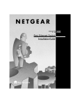
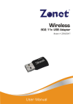
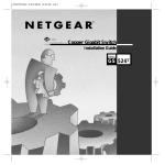
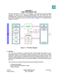
Start Here
The NETGEAR™ Model FS516 16-Port Fast Ethernet Switch and Model FS524
24-Port Fast Ethernet Switch provide you with a low-cost, high-performance
network solution and are designed to support power workgroups operating at
either 10 megabits per second (Mbps) or 100 Mbps.
Ethernet switches provide private, dedicated, 10 Mbps (or 100 Mbps) capacity
to each connected PC/server or hub/workgroup segment, which is significantly
higher than in a shared environment. The higher bandwidth enables the use of
applications such as multimedia, imaging, video, or high-performance clientserver functions among users who are spread out over the network.
With both the Model FS516 switch and the Model FS524 switch, improvement
is accomplished very easily, with no change to the desktop (the network
interface cards or software and the network wiring). As a result, the performance
upgrade and the applications it enables are obtained very quickly and at a low
cost.
Features
The Model FS516 and Model FS524 switches have the following key features:
•
•
Sixteen (Model FS516) or twenty-four (Model FS524) automatic speedsensing (autosensing) 10/100 Mbps Ethernet ports to provide fast
information exchange, resource sharing, and client or peer-to-peer
communication using simple Category 5 unshielded twisted pair (UTP)
cable
Automatic address learning function to build the packetforwarding information table
The table contains up to 4,000 MAC addresses for the Model FS516 and
up to 8,000 MAC addresses for the Model FS524 (that is, the switch can
support networks with as many as 8,000 devices).
•
Switch-selectable autonegotiating or full-duplex mode of operation
Full-duplex mode doubles throughput of point-to-point connections by
letting individual ports transmit and receive concurrently when the other
end also supports full-duplex mode. The default is half-duplex if the
connected device does not support N-way negotiation. The duplex toggle
switch can be set to full-duplex if the connected port is operating at fullduplex mode.
•
Wire-speed filtering and forwarding to provide “traffic cop” function by
directing traffic to the appropriate route without slowing down the traffic
Store-and-forward forwarding node to minimize erroneous packets on the
network
•
•
Half-duplex backpressure
Easy Plug-and-Play installation with no software to configure, which saves
time and minimizes the potential for configuration errors
Model FS516/FS524 Fast Ethernet Switch Installation Guide
•
Normal/Uplink push button to simplify network extension
The switch can be connected to a hub using a simple, straight-through
cable.
•
•
Protocol independence and compatibility with all common protocols such as
TCP/IP, NetWare, DECnet, and Microsoft Networks
Vista RJ-45 network ports with built-in LEDs to monitor individual port
status
Package Contents
Model FS516 or Model FS524 switch
(Model FS516 shown)
Auto 10/100 Mbps
MODEL
FS516
10/100 Mbps
16PORT
10/100Mbps
Fast Ethernet Switch
Utilization%
10/100 Mbps
8
1
Link
FDX
Link
FDX
Normal/Uplink
Power
Utilization%
13
Rubber
footpads
16
AC
power
cord
Rack mount
kit
Installation guide,
Warranty & Owner
Registration Card,
Support Information Card
9191FA
Verify that your package contains the following:
•
•
•
•
•
•
•
Model FS516 or Model FS524 switch
Rubber footpads for tabletop installation
This installation guide
Rack mount kit for 19-inch rack installation
Warranty & Owner Registration Card
Support Information Card
Power cord
Model FS516/FS524 Fast Ethernet Switch Installation Guide
Product Illustration
Front Panel
The front panel of the Model FS516/FS524 switch contains the following LEDs
that correspond to each network port located on the hub: Rx/Tx/Collision and
100 Mbps. Each vista RJ-45 network port has its own Link LED (located at the
top left corner of each 10/100 Mbps port), and full-duplex (FDX) LED (located
at the top right corner of each 10/100 Mbps port).
Front Panel of the Model FS516 Switch
Auto 10/100 Mbps
MODEL
FS516
10/100 Mbps
16PORT
10/100Mbps
Fast Ethernet Switch
1
Utilization%
10/100 Mbps
8
Link
FDX
Link
FDX
Normal/Uplink
Power
Utilization%
13
16
Front Panel of the Model FS524 Switch
100 Mbps
LEDs
10/100 Mbps
ports
Auto 10/100 Mbps
MODEL
FS524
10/100 Mbps
24PORT
10/100Mbps
Fast Ethernet Switch
Utilization%
10/100 Mbps
1
12
Link
FDX
Link
FDX
Normal/Uplink
Power
Utilization%
Power LED
13
24
Rx/Tx
Collision LEDs
Normal/Uplink
push button
9189FA
Model FS516/FS524 Fast Ethernet Switch Installation Guide
LEDs
The table below describes the activity of the LEDs.
Label
Color
Activity
Description
Pwr (Power)
Green
On
Off
Power is supplied to the switch.
Power is disconnected.
Rx/Tx/Collision Green
Blinking
Packet transmission or reception is occurring
on the port. The blinking action corresponds to
the number of packets that are transmitted or
received.
Yellow
Blinking
Data collisions are occurring on the port. The
blinking corresponds to the number of
collisions. When a collision occurs, the
connected device pauses and transmits again
after waiting a specified time.
Green
On
The port is operating in 100 Mbps mode.
Off
The port is operating in 10 Mbps mode.
On
A valid link is established on the port.
Off
A link is not established on the port.
On
The port is operating in full-duplex mode.
Off
The port is operating in half-duplex mode.
100 Mbps
Link
FDX
Green
Green
Vista RJ-45 Network Ports with Built-in LEDs
All of the ports on the switch are 10/100 Mbps capable autosensing Ethernet
ports. Each port supports only unshielded twisted pair (UTP) cable using an 8pin RJ-45 plug. Each port uses vista RJ-45 connectors that have two LEDs—the
Link LED and the FDX LED.
Link
FDX
8923EB
Normal/Uplink Push Button
The Normal/Uplink push button on the front panel of the switch allows you to
select uplink (MDI) or normal (MDI-X) wiring for port 16 on the Model FS516
switch and port 24 on the Model FS524 switch. These ports are configured for
normal wiring to connect to a PC when the push button is in the out position.
When the push button is pressed in, these ports are configured for uplink wiring
to connect to another switch or to a hub, using a straight-through twisted pair
cable.
Model FS516/FS524 Fast Ethernet Switch Installation Guide
Rear Panel
The rear panel of the Model FS516/FS524 switch has full-duplex (FDX) and
auto-duplex (AUTO) toggle switches, fans for cooling, and a standard AC power
receptacle for the supplied power cord.
Rear Panel of the Model FS516 Switch
AUTO FDX -
Enable port to determine duplex mode automatically
Force port to operate at Full Duplex and Half Duplex mode only
1
10/100 Mbps
8 1
8
FDX
AUTO
100-240 VAC 50-60 Hz 0.5A
Rear Panel of the Model FS524 Switch
FDX and AUTO
duplex toggle switches
AUTO FDX -
Fans
AC power
outlet
Enable port to determine duplex mode automatically
Force port to operate at Full Duplex and Half Duplex mode only
1
10/100 Mbps
12 1
12
FDX
AUTO
100-240 VAC 50-60 Hz 0.5A
9190FA
FDX/AUTO Duplex Toggle Switches
Full-duplex mode is supported for all 10/100 Mbps ports and allows a port to
transmit and receive data at the same time. Full-duplex operation applies only to
point-to-point access (for example, when a switch is connected to a PC, a server,
or another switch).
Setting the toggle switch to AUTO on the 10/100 Mbps port enables the port to
determine duplex mode automatically. In this mode, the 10/100 Mbps port
operates in either full- or half-duplex mode, depending on the operating mode of
the remote port. If supported by the remote node, the port will establish a 100
Mbps full-duplex link as the default. If the remote port cannot provide the
proper signal to indicate its own capability, the 10/100 Mbps port on the switch
defaults to half-duplex mode. Because repeaters and hubs use a common
collision domain for all communications and cannot communicate in full-duplex
mode, the associated 10/100 Mbps port on the switch should be set to autoduplex operation when connecting to these types of devices.
Setting the toggle switch to FDX on the 10/100 Mbps port enables the port to
determine the speed but will set the duplex mode to full-duplex.
Model FS516/FS524 Fast Ethernet Switch Installation Guide
.
Applications
The Model FS516/FS524 switch is designed to provide flexibility in configuring
your network connections. Each switch can be used as a standalone device or
can be used with 10 Mbps or 100 Mbps hubs or other interconnection devices in
various configurations. The configuration examples in this section illustrate the
integration of the switches in network environments of all sizes and types. These
examples include a network of a few workstations connected to a printer or a
segmented network with multiple users or workgroups and other networking
devices.
Desktop Switching
The Model FS516/FS524 switch is used as a desktop switch to build a small
network that enables users to have 100 Mbps access to a file server. If a fullduplex adapter card is installed in the server or PC, a 200 Mbps connection is
possible on the port where the server or PC is connected.
Key
100 Mbps
10 Mbps
Model FS516
switch
Auto 10/100 Mbps
16PORT
10/100Mbps
MODEL
FS516
Fast Ethernet Switch
Link
FDX
9193FA
Segment Switching and Bridging from 10 Mbps to 100 Mbps
The Model FS516/FS524 switch is used to segment a network into multiple connected pieces,
increasing overall bandwidth and throughput. Both switch models can segment networks that are
built with the NETGEAR Model DS508 and Model EN516 hubs and can function as bridges
connecting traditional 10BASE-T Ethernet networks to 100BASE-TX Fast Ethernet networks.
Model FS524 switch
Auto 10/100 Mbps
24PORT
10/100Mbps
Model DS508
hub
MODEL
FS524
Fast Ethernet Switch
Model RT328
router
Model EN516
hub
9194FA
Model FS516/FS524 Fast Ethernet Switch Installation Guide
Prepare the Site
Before you begin installing your switch, prepare the installation site. Make sure
your operating environment meets the operating environment requirements of
the equipment.
Characteristic
Requirement
Temperature
Ambient temperature between 0° and 40° C (32° and 104° F).
No nearby heat sources such as direct sunlight, warm air
exhausts, or heaters.
Operating humidity
Maximum relative humidity of 90%, noncondensing.
Ventilation
Minimum 2 inches (5.08 cm) on all sides for cooling.
Adequate airflow in room or wiring closet.
Operating
conditions
At least 6 feet (1.83 m) to nearest source of electromagnetic noise
(such as photocopy machine or arc welder).
Power
Adequate power source within 6 feet (1.83 m).
Install the Switch
To install your switch on a flat surface, you do not need any special tools. Be
sure the switch is positioned with at least 2 inches of space on all sides for
ventilation.
To install the switch in a rack, first attach the mounting brackets to the side of
the switch. Insert the screws provided in the rack mount kit through each bracket
and into the bracket mounting holes in the switch. Tighten the screws with a #1
Phillips screwdriver to secure each bracket. Align the mounting holes in the
brackets with the holes in the rack and insert two pan-head screws with nylon
washers through each bracket and into the rack. Tighten the screws with a #2
Phillips screwdriver to secure the switch in the rack.
Model FS516/FS524 Fast Ethernet Switch Installation Guide
Connect Devices to the Switch
Before connecting the switch, be sure you review “Applications” for information
about determining the appropriate configuration for your networking needs.
To connect the switch:
1. Connect the devices to the 10/100 Mbps ports on the switch, using
Category 5 UTP cable and an RJ-45 plug.
Note: Ethernet specifications limit the cable length between your PC or server and the
switch to 328 feet (100 meters) in length.
2. Set the Normal/Uplink push button.
3. Set the FDX/AUTO toggle switches on the rear panel for the selected
duplex mode (the default setting is AUTO).
4. Connect one end of the DC power adapter cable to the power outlet on
the rear panel of the switch and the other end of the power adapter
cable to the wall outlet.
Refer to the following illustration when connecting the switch. Each of the
preceding steps has a corresponding reference number in the illustration.
Key
100 Mbps
10 Mbps
3
1
8
Duple
x Mod
e
FDX
AUTO
**
16POR
T
10/10
0Mbp
s
Fas
t Ethe
rnet
Swit
ch
Aut
10/1
00
Pow
er
o 10/
100
Mbp
s
Utiliz
10/1 ation
00 %
Mbp
s
Mb
ps
4
Utiliz
ation
%
1
Link
FDX
13
Link
FDX
MODE
L
FS
516
8
Norm
al/Up
link
16
1
2
Normal/
Uplink
*
RJ-45
connector
*
**
Normal/Uplink push button set to the Normal position for connection
to the server.
For a typical configuration, set toggle switches to AUTO. For more
information, refer to "FDX/AUTO Duplex Toggle Switches."
9195FA
Model FS516/FS524 Fast Ethernet Switch Installation Guide
Twisted Pair Cables
For two devices to communicate, the transmitter of each device must be
connected to the receiver of the other device. The crossover function is usually
implemented internally as part of the circuitry in the device. Most ports on
switches and repeaters have media-dependent interfaces with crossover ports.
These ports are referred to as MDI-X or normal ports. Computer and
workstation adapter cards are usually media-dependent interface ports referred
to as MDI or uplink ports.
These two figures illustrate the use of straight-through and crossover twisted
pair cables.
Uplink or
MDI port
Tx
Rx
Straight-through
twisted pair cable
Normal or
MDI-X port
1
1
2
2
3
3
6
6
Normal or
MDI-X port
Crossover
twisted pair cable
Rx
Tx
Normal or
MDI-X port
Rx
1
2
1
Rx
2
Tx
3
6
3
Tx
6
8146EC
RJ-45 Connector
The RJ-45 connector (shown in the illustration with an RJ-45 plug) is used to
connect workstations, hubs, and switches through unshielded twisted pair cable.
The RJ-45 connector accepts four-pair Category 3 or Category 5 UTP cable.
12345678
8
1
711EA
RJ-45
Connector
Pin
Assignment
Normal Assignment
on Ports 1–8,
1–16, or 1–24
Uplink Assignment
on Port 8, 16, or 24
1
Input Receive Data +
Output Transmit Data +
2
Input Receive Data -
Output Transmit Data -
3
Output Transmit Data +
Input Receive Data +
6
Output Transmit Data -
Input Receive Data -
4, 5, 7, 8
Not used
Not used
Model FS516/FS524 Fast Ethernet Switch Installation Guide
Verify Installation
When power has been applied to the switch:
•
•
The green Pwr (Power) LED on the front panel is on.
The green Link LED on each connected port is on.
When the switch is connected and operating, refer to the table in “LEDs” for
information about the LEDs and their activity.
Troubleshooting Information
Symptom
Cause
Solution
Power LED is
off.
No power is
received at the
hub.
Check the power cord connections for the switch
and the connected device.
Check for a defective adapter card, cable, or
port by testing them in an alternate environment
where all products are functioning.
Make sure all cables used are correct and
comply with Ethernet specifications.
Link LED is off or Port connection is
intermittent.
not functioning.
Check the crimp on the RJ-45 connectors and
make sure that the plug is properly inserted and
locked into the port at both the switch and the
connecting device.
Make sure all cables used are correct and
comply with Ethernet specifications.
File transfer is
Half- or full-duplex Make sure the 10/100 Mbps port is set to autoslow or
setting on the
duplex (AUTO) mode when connecting the
performance
NETGEAR switch switch to a repeater or hub.
degradation is a and the connected
problem.
device are not the
same.
One or more
Not all system
components are components are
malfunctioning. properly installed.
Test the components in an alternate
environment where all other components are
functioning properly.
A segment or
device is not
recognized as
part of the
network.
One or more
devices are not
properly
connected, or
cabling does not
meet Ethernet
guidelines.
Verify that the cabling is correct. Be sure all
cable connectors are securely positioned in the
required ports. Straight-through cables should
be used for all standard twisted pair
connections. Make sure all devices are
connected to the network. Equipment may have
been accidentally disconnected.
Rx/Tx/Collision
LED is blinking
yellow
Collisions are
occurring on the
connected
segment.
This situation is normal in Ethernet operation
when ports/segments are configured for halfduplex mode.
Duplex modes are
mismatched.
Recheck the duplex toggle switch settings and
the remote link configuration.
Model FS516/FS524 Fast Ethernet Switch Installation Guide
Technical Specifications
General Specifications
Network Protocol and
Standards Compatibility
Model FS516 Fast Ethernet Switch
Model FS524 Fast Ethernet Switch
ISO/IEC 802-3 (ANSI/IEEE 802.3i) 10BASE-T Ethernet
IEEE 802.3u,100BASE-TX Fast Ethernet
Data Rate
100 Mbps with 4B/5B encoding and MLT-3 physical interface for 100BASE-TX
10 Mbps differential Manchester encoded
Interface
RJ-45 connector for 10BASE-T or 100BASE-TX Ethernet interface
42 W
Power Consumption
100–240 V AC
Input Voltage (Power Adapter)
Physical Specifications
Dimensions:
13.0 x 1.7 x 8.0 in.
33.0 x 4.3 x 20.7 cm
Weight:
5.5 lb; 2.5 kg
6.0 lb; 2.6 kg
Environmental Specifications
Operating temperature:
Operating humidity:
Electromagnetic Emissions
0° to 40° C (32° to 104° F)
90% maximum relative humidity, noncondensing
CE mark, commercial; FCC Part 15 Class A; EN 55 022 (CISPR 22), Class A;
VCCI Class A
Electromagnetic Compliance
CE mark, commercial
Electrostatic discharge (ESD):
FCC Part 15 Class A
Radiated electromagnetic field:
Electrical fast transient/burst:
VCCI Class A
EN 55022 (CISPR 22) Class A, EN50082-1
Electrical surge:
Safety Agency Approvals
C-Tick
UL listed (UL 1950), cUL
TUV licensed (EN 60 950), IEC 950
Performance Specifications
Frame filter rate:
14,800 frames/second, maximum on 10 Mbps port
148,000 frames/second, maximum on 100 Mbps port
Frame forward rate:
14,800 frames/second, maximum on 10 Mbps port
148,000 frames/second, maximum on 100 Mbps port
Network latency (using 64-byte
packets):
10 Mbps to 10 Mbps: 73 microseconds maximum
10 Mbps to 100 Mbps: 26 microseconds maximum
100 Mbps to 10 Mbps: 62 microseconds maximum
100 Mbps to 100 Mbps: 15 microseconds maximum
Address database size:
Addressing:
4,000 media access control (MAC)
addresses
8,000 media access control (MAC)
addresses
48-bit MAC address
Queue buffer:
64 KB memory per port
512 KB memory per port
Model FS516/FS524 Fast Ethernet Switch Installation Guide
© 1999 by NETGEAR, Inc. All rights reserved.
Trademarks
Bay Networks is a registered trademark of Bay Networks, Inc.
NETGEAR is a trademark of Bay Networks, Inc.
All other trademarks and registered trademarks are the property of their respective owners.
Statement of Conditions
In the interest of improving internal design, operational function, and/or reliability, NETGEAR
reserves the right to make changes to the products described in this document without notice.
NETGEAR does not assume any liability that may occur due to the use or application of the
product(s) or circuit layout(s) described herein.
Certificate of the Manufacturer/Importer
It is hereby certified that the NETGEAR Model FS516/FS524 Fast Ethernet Switch has been
suppressed in accordance with the conditions set out in the BMPT-AmtsblVfg 243/1991 and Vfg
46/1992. The operation of some equipment (for example, test transmitters) in accordance with the
regulations may, however, be subject to certain restrictions. Please refer to the notes in the
operating instructions.
Federal Office for Telecommunications Approvals has been notified of the placing of this
equipment on the market and has been granted the right to test the series for compliance with the
regulations.
Voluntary Control Council for Interference (VCCI) Statement
This equipment is in the first category (information equipment to be used in commercial and/or
industrial areas) and conforms to the standards set by the Voluntary Control Council for
Interference by Data Processing Equipment and Electronic Office Machines that are aimed at
preventing radio interference in commercial and/or industrial areas.
Consequently, when this equipment is used in a residential area or in an adjacent area thereto,
radio interference may be caused to equipment such as radios and TV receivers.
Federal Communications Commission (FCC) Compliance Notice:
Radio Frequency Notice
This device complies with part 15 of the FCC Rules. Operation is subject to the following two
conditions:
This device may not cause harmful interference.
This device must accept any interference received, including interference that may cause
undesired operation.
Note: This equipment has been tested and found to comply with the limits for a Class A digital
device, pursuant to part 15 of the FCC Rules. These limits are designed to provide reasonable
protection against harmful interference in a residential installation. This equipment generates,
uses, and can radiate radio frequency energy and, if not installed and used in accordance with the
instructions, may cause harmful interference to radio communications. However, there is no
guarantee that interference will not occur in a particular installation. If this equipment does cause
harmful interference to radio or television reception, which can be determined by turning the
equipment off and on, the user is encouraged to try to correct the interference by one or more of
the following measures:
Reorient or relocate the receiving antenna.
Increase the separation between the equipment and receiver.
Connect the equipment into an outlet on a circuit different from that to which the receiver is
connected.
Consult the dealer or an experienced radio/TV technician for help.
EN 55 022 Declaration of Conformance
This is to certify that the NETGEAR Model FS516/FS524 Fast Ethernet Switch is shielded against
the generation of radio interference in accordance with the application of Council Directive 89/
336/EEC, Article 4a. Conformity is declared by the application of EN 55 022 Class A (CISPR 22).
Model FS516/FS524 Fast Ethernet Switch Installation Guide
Canadian Department of Communications Radio Interference Regulations
This digital apparatus (NETGEAR Model FS516/FS524 Fast Ethernet Switch) does not exceed
the Class A limits for radio-noise emissions from digital apparatus as set out in the Radio
Interference Regulations of the Canadian Department of Communications.
Règlement sur le brouillage radioélectrique du ministère des Communications
Cet appareil numérique (NETGEAR Model FS516/FS524 Fast Ethernet Switch) respecte les
limites de bruits radioélectriques visant les appareils numériques de classe A prescrites dans le
Règlement sur le brouillage radioélectrique du ministère des Communications du Canada.
Model FS516/FS524 Fast Ethernet Switch Installation Guide
NETGEAR, Inc.
A Bay Networks Company
4401 Great America Parkway
Santa Clara, CA 95054 USA
Phone: 888-NETGEAR
http://WWW.NETGEARinc.com
*m-fs500na-0*
Model FS516/FS524 Fast Ethernet Switch Installation Guide