1
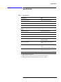
776D Dual Directional Coupler
Operating and Service
Manual
Manual part number: 00776-90010
Printed in USA
May 2001
Supersedes: June 2000
Revision 3.1
Notice
The information contained in this document is subject to change without
notice.
Agilent Technologies makes no warranty of any kind with regard to this
material, including, but not limited to, the implied warranties of
merchantability and fitness for a particular purpose. Agilent Technologies
shall not be liable for errors contained herein or for incidental or
consequential damages in connection with the furnishing, performance, or
use of this material.
Agilent Technologies assumes no responsibility for the use or reliability of
its software on equipment that is not furnished by Agilent Technologies.
This document contains proprietary information which is protected by
copyright. All rights are reserved. No part of this document may be
photocopied, reproduced, or translated to another language without prior
written consent of Agilent Technologies.
RESTRICTED RIGHTS LEGEND
Use, duplication, or disclosure by the U.S. Government is subject to
restrictions as set forth in subparagraph (c)(1)(ii) of the Rights in Technical
Data and Computer Software clause at DFARS 252.227-7013 for DOD
agencies, and subparagraphs (c)(1) and (c)(2) of the Commercial Computer
Software Restricted Rights clause at FAR 52.227-19 for other agencies.
Agilent Technologies, Inc.
1400 Fountaingrove Parkway
Santa Rosa, CA 95403-1799, U.S.A.
© Copyright 2000-2001
Agilent Technologies, Inc.
ii Agilent 776D Operating And Service Manual
In This Manual…
•
•
•
•
•
Overview, page 1
Specifications, page 3
Installation, page 4
Storage and Shipment, page 6
Performance Tests, page 7
Agilent 776D Operating And Service Manual iii
Warranty
Custom systems are warranted by contractual agreement between Agilent
Technologies and the customer.
Certification
Agilent Technologies, Inc., certifies that this product met its published
specifications at the time of shipment from the factory. Agilent Technologies
further certifies that its calibration measurements are traceable to the
United States National Institute of Standards and Technology (NIST,
formerly NBS), to the extent allowed by the Institute’s calibration facility,
and to the calibration facilities of other International Standards
Organization members.
Warranty
This Agilent Technologies system product is warranted against defects in
materials and workmanship for a period corresponding to the individual
warranty periods of its component products. Instruments are warranted for a
period of one year. During the warranty period, Agilent Technologies will, at
its option, either repair or replace products that prove to be defective.
Warranty service for products installed by Agilent Technologies and certain
other products designated by Agilent Technologies will be performed at
Buyer’s facility at no charge within Agilent Technologies service travel
areas. Outside Agilent Technologies service travel areas, warranty service
will be performed at Buyer’s facility only upon Agilent Technologies’ prior
agreement and Buyer shall pay Agilent Technologies’ round trip travel
expenses. In all other areas, products must be returned to a service facility
designated by Agilent Technologies.
For products returned to Agilent Technologies for warranty service, Buyer
shall prepay shipping charges to Agilent Technologies and Agilent
Technologies shall pay shipping charges to return the product to Buyer.
However, Buyer shall pay all shipping charges, duties, and taxes for products
returned to Agilent Technologies from another country.
Agilent Technologies warrants that its software and firmware designated by
Agilent Technologies for use with an instrument will execute its
programming instructions when properly installed on that instrument.
Agilent Technologies does not warrant that the operation of the instrument,
or software, or firmware will be uninterrupted or error free.
LIMITATION OF WARRANTY. The foregoing warranty shall not apply
to defects resulting from improper or inadequate maintenance by Buyer,
Buyer-supplied software or interfacing, unauthorized modification or
misuse, operation outside of the environmental specifications for the
product, or improper site preparation or maintenance.
iv Agilent 776D Operating And Service Manual
NO OTHER WARRANTY IS EXPRESSED OR IMPLIED. AGILENT
TECHNOLOGIES SPECIFICALLY DISCLAIMS THE IMPLIED
WARRANTIES OR MERCHANTABILITY AND FITNESS FOR A
PARTICULAR PURPOSE.
EXCLUSIVE REMEDIES. THE REMEDIES PROVIDED HEREIN ARE
BUYER’S SOLE AND EXCLUSIVE REMEDIES. AGILENT
TECHNOLOGIES SHALL NOT BE LIABLE FOR ANY DIRECT,
INDIRECT, SPECIAL, INCIDENTAL, OR CONSEQUENTIAL
DAMAGES, WHETHER BASED ON CONTRACT, TORT, OR ANY
OTHER LEGAL THEORY.
YEAR 2000. Agilent Technologies warrants that each Agilent Technologies
hardware, software, and firmware product on Agilent Technologies’
Corporate Price List (dated July 1, 1998 or later) delivered under the
product’s contract of sale will be able to accurately process date data
(including, but not limited to, calculating, comparing, and sequencing) from,
into, and between the twentieth and twenty-first centuries, and the years
1999 and 2000, including leap year calculations, when used in accordance
with the product documentation provided that all other products (that is,
hardware, software, firmware) used in combination with such Agilent
Technologies product(s) properly exchange date data with it. If the
agreement requires that specific Agilent Technologies products must
perform as a system in accordance with the foregoing warranty, then that
warranty will apply to those Agilent Technologies products as a system, and
Customer retains sole responsibility to ensure the year 2000 readiness of its
information technology and business environment. The duration of this
warranty extends through January 31, 2001.
The remedies available under this warranty will be defined in, and subject to,
the terms and limitations of the warranties contained in the contract of sale.
To the extent permitted by local law, this warranty applies only to branded
Agilent Technologies products and not to products manufacture by others
that may be sold or distributed by Agilent Technologies. Nothing in this
warranty will be construed to limit any rights or remedies provided
elsewhere in the contract of sale with respect to matters other than year 2000
compliance.
Assistance
Product maintenance agreements and other customer assistance agreements
are available for Agilent Technologies products.
For assistance, call your local Agilent Technologies Sales and Service Office
(refer to “Service and Support Any adjustment, maintenance, or repair of
this product must be performed by qualified personnel. Contact your
customer engineer through your local Agilent Technologies Service Center.
You can find a list of local service representatives on the Web at the address
below.” on page vi).
Agilent 776D Operating And Service Manual v
Service and Support
Any adjustment, maintenance, or repair of this product must be
performed by qualified personnel. Contact your customer engineer
through your local Agilent Technologies Service Center. You can find a
list of local service representatives on the Web at the address below.
Online assistance: www.agilent.com/find/assist
United States
(tel) 1 800 452 4844
Latin America
(tel) (305) 269 7500
(fax) (305) 269 7599
Canada
(tel) 1 877 894 4414
(fax) (905) 282-6495
New Zealand
(tel) 0 800 738 378
(fax) (+64) 4 495 8950
Japan
(tel) (+81) 426 56 7832
(fax) (+81) 426 56 7840
Australia
(tel) 1 800 629 485
(fax) (+61) 3 9210 5947
Europe
(tel) (+31) 20 547 2323
(fax) (+31) 20 547 2390
Asia Call Center Numbers
Country
Phone Number
Fax Number
Singapore
1-800-375-8100
(65) 836-0252
Malaysia
1-800-828-848
1-800-801664
Philippines
(632) 8426802
1-800-16510170 (PLDT Subscriber
Only)
(632) 8426809
1-800-16510288 (PLDT
Subscriber Only)
Thailand
(088) 226-008 (outside Bangkok)
(662) 661-3999 (within Bangkok)
(66) 1-661-3714
Hong Kong
800-930-871
(852) 2506 9233
Taiwan
0800-047-866
(886) 2 25456723
People’s Republic of
China
800-810-0189 (preferred)
10800-650-0021
10800-650-0121
India
1-600-11-2929
000-800-650-1101
vi Agilent 776D Operating And Service Manual
Safety and Regulatory Information
Review this product and related documentation to familiarize yourself with
safety markings and instructions before you operate the instrument. This
product has been designed and tested in accordance with international
standards.
WARNING
The WARNING notice denotes a hazard. It calls attention to a procedure,
practice, or the like, that, if not correctly performed or adhered to, could result
in personal injury. Do not proceed beyond a WARNING notice until the
indicated conditions are fully understood and met.
CAUTION
The CAUTION notice denotes a hazard. It calls attention to an operating
procedure, practice, or the like, which, if not correctly performed or adhered
to, could result in damage to the product or loss of important data. Do not
proceed beyond a CAUTION notice until the indicated conditions are fully
understood and met.
Instrument Markings
!
When you see this symbol on your instrument, you should refer to the instrument’s
instruction manual for important information.
This symbol indicates hazardous voltages.
The laser radiation symbol is marked on products that have a laser output.
This symbol indicates that the instrument requires alternating current (ac) input.
The CE mark is a registered trademark of the European Community. If it is
accompanied by a year, it indicates the year the design was proven.
The CSA mark is a registered trademark of the Canadian Standards Association.
1SM1-A
This text indicates that the instrument is an Industrial Scientific and Medical Group 1
Class A product (CISPER 11, Clause 4).
This symbol indicates that the power line switch is ON.
This symbol indicates that the power line switch is OFF or in STANDBY position.
Agilent 776D Operating And Service Manual vii
Safety Earth
Ground
This is a Safety Class I product (provided with a protective earthing
terminal). An uninterruptible safety earth ground must be provided from the
main power source to the product input wiring terminals, power cord, or
supplied power cord set. Whenever it is likely that the protection has been
impaired, the product must be made inoperative and secured against any
unintended operation.
Before Applying Power
Verify that the product is configured to match the available main power
source as described in the input power configuration instructions in this
manual. If this product is to be powered by autotransformer, make sure the
common terminal is connected to the neutral (grounded) side of the ac power
supply.
viii Agilent 776D Operating And Service Manual
Overview
This operating note contains operating information for the Agilent 776D
dual directional coupler. Since the 776D must be returned to Agilent
Technologies for repair, no service information is given. Instrument
specifications are listed in Table 1. These specifications are the performance
standards, or limits against which the instrument may be tested. Figure 1
defines the terms used in Table 1 and throughout this manual.
Figure 1
Description
Coupler Terminology
The 776D is a dual directional coupler designed for use in 50-ohm coaxial
systems. In this coupler, nominal coupling is 20 dB. The coupling variation
with frequency of each auxiliary arm is marked on the nameplate opposite
the appropriate auxiliary arm.
Agilent 776D Operating and Service Manual 1
Overview
Network Analyzer
Reflectometer
A network analyzer with either phase magnitude display, phase gain display
or polar display, with a sweep generator with appropriate RF unit plug-in,
may be used with the 776D as a reflectometer test setup. The network
analyzer reflectometer may be used either for fixed frequency or swept
frequency measurements.
Fixed Frequency
Reflectometer
A SWR meter with a sweep oscillator, with appropriate plug-in RF unit, or
other signal source may be used with the 776D as a fixed frequency
reflectometer.
Swept Frequency
Reflectometer
A frequency response test set or network analyzer system together with a
sweep oscillator with appropriate plug-ins may be used as a swept frequency
reflectometer.
A SWR meter with a sweep oscillator and a 140 or 180 oscilloscope with
appropriate plug-ins may be used as a swept frequency reflectometer.
2 Agilent 776D Operating and Service Manual
Specifications
Specifications
Table 1
Specifications
Characteristics
Value
Primary line insertion loss
Approximately 0.35 dB maximum
Minimum directivity 1
40 dB
Nominal coupling attenuation (each secondary arm)
20 dB
Accuracy of coupling (each secondary arm)
Mean coupling 20 dB + 0.5 dB
Maximum coupling variation (each secondary coupling
value)
± 1 dB of specified mean coupling value
Auxiliary arm tracking 2
Equal to or less than 0.3 dB
Maximum primary line VSWR 1
1.15
Maximum auxiliary arm VSWR
1.20
Primary line power handling capacity
50 watts average or 10 kW peak
Primary line connector 3
Agilent compatible Type N connectors, one
male and one female
Auxiliary arm connectors 3
Agilent compatible Type N connectors,
female
Accessories available
Agilent 11511A Type N Female Shorting
Jack
Agilent 11512A Type N Male Shorting Plug
Dimension
6-5/16 in x 2-5/16 in x 1-3/4 in
(161 mm x 59 mm x 45 mm)
Net weight
2 lb (0.9 kg)
1. Measured with Agilent sliding load.
2. Maximum change in coupling curve of one secondary arm relative to the other.
3. Agilent Type N connectors mate with standard Type N connectors (see text)
Agilent 776D Operating and Service Manual 3
Installation
Installation
Initial Inspection
Inspect the shipping container for damage. If the shipping container or
cushioning material is damaged, it should be kept until the contents of the
shipment have been checked for completeness and the instrument has been
checked mechanically and electrically. Procedures for checking electrical
performance are given in "“Performance Tests” on page 7". If the contents
are incomplete, if there is mechanical damage or defect, or if the instrument
does not pass the electrical performance test, notify the nearest Agilent
Technologies office. If the shipping container is damaged, or the cushioning
material shows signs of stress, notify the carrier as well as the Agilent
Technologies office. Keep the shipping materials for the carrier's inspection.
The Agilent office will arrange for repair or replacement without waiting for
claim settlement.
Mating Connectors
Type N mating connectors used with the 776D should have dimensions
compatible with US Military Standard MIL-C-39012.
N-female Pin Depth:
+0.207 inches to +0.201 inches
(effective 0 to–0.006 inches)
N-male Pin Depth:
–0.207 inches to –0.213 inches
(effective 0 to –0.006 inches)
Operating
Environment
Operate the 776D in the range from 0 °C to +55 °C and protect it from
excessive humidity.
CAUTION
Do not heat cycle this coupler during use or storage. Keep coupler near room
temperature (25 °C).
Installation
Instructions
Support Weight
When installing the 776D, be sure the auxilliary equipment supports its own
weight. The coupler, particularly the connectors are not designed to support
weight.
4 Agilent 776D Operating and Service Manual
Installation
CAUTION
Do not drop the coupler. While the coupler probably with not break, it can be
jarred out of adjustment and the connectors can be damaged.
On the bottom of each coupler is supported by four plastic feet (part number
0361-0207). The feet are inserts in 8-32 tapped holes (0.50 in deep) and may
be removed to mount the coupler. Dimensions between mounting holes are
shown in Figure 2.
Figure 2
Signal Flow
Figure 3
Dimensions of Trapped Mounting Holes
Signal flow is indicated in Figure 3. Coupling is indicated by arrows. The
776D is bi-directional (signal may go through the coupler in either
direction).
Type N Connector Dimensions
Agilent 776D Operating and Service Manual 5
Storage and Shipment
Storage and Shipment
Environment
The 776D may be stored in surroundings between –40 °C and +75 °C.
However, heat cycling should be avoided by storing at an even room
temperature (25 °C) if at all possible. The greater the heat cycling, the
greater chance of dimensional change of the printed circuit board resulting in
out-of-specification operation.
Original Packaging
Containers and materials identical to those used in factory packaging are
available through Agilent Technologies offices. If the instrument is being
returned to Agilent office for servicing, attach a tag indicating the type of
service required, return address, model number, and full serial number. Also,
mark the container FRAGILE to assure careful handling. In any
correspondence, refer to the instrument by model number and full serial
number.
Other Packaging
The following general instructions should be used for repackaging with
commercially available materials:
1. Wrap the instrument in heavy paper or plastic. (If shipping to a Agilent
Technologies office or service center, attach a tag indicating the type of
service required, return address, model number, and full serial number.)
2. Use a strong shipping container. A single wall carton made of
200-pound test material is adequate.
3. Use enough shock-absorbing material (3 to 4-inch layer) around all sides
of the instrument to provide firm cushion and prevent movement inside
the container.
4. Seal the shipping container securely.
5. Mark the shipping container FRAGILE to assure careful handling.
6 Agilent 776D Operating and Service Manual
Performance Tests
Performance Tests
The performance tests check the instrument’s electrical performance using
the specifications of Table 1 on page -3 as the performance standards.
Coupling Test
Specification
Figure 4
Procedure
• Mean Coupling, 20 dB ± 0.5 dB
• Maximum Coupling Variation, ± l dB of mean coupling.
Coupling Test Setup
1. Set up the equipment as shown in Figure 5.
2. Set the SWR meter to maximum bandwidth, 50 dB range.
3. With 1000 Hz square-wave modulation, tune SWR meter FREQ control
for a maximum indication. Set the SWR meter GAIN control for an
indication of 0 dB on the meter.
4. Observe the waveform while sweeping the oscillator manually from 940
to 1900 MHz. If the waveform is not square:
a. Adjust the loop gain of the oscillator. If still not square,
b. Add a 10 dB attenuator to the 20 dB attenuator, and repeat step 4.
5. Adjust the gain of the SWR meter to 0 dB on the 50 dB-NORMAL
range on the SWR meter and run a calibration line on the X-Y recorder.
6. Set level to 0.5 dB and run a calibration line.
7. Set level to 1.0 dB and run a calibration line.
Agilent 776D Operating and Service Manual 7
Performance Tests
8. Set level to 1.5 dB and run a calibration line.
9. Set level to 2.0 dB and run a calibration line.
10. Adjust the gain of the SWR meter for an indication of 1 dB. Remove the
20 dB attenuator and insert the 776D under test, as shown in Figure 4.
Run a test trace. See Figure 5. The test trace should have a variation of
less than ± l dB and the mean coupling should be between 19.5 and 20.5
dB.
11. Reverse the 776D under test end-for-end and repeat the test for coupling
on the other arm.
Figure 5
Coupling Test Trace
8 Agilent 776D Operating and Service Manual
Performance Tests
Directivity Test
Specification:
Figure 6
Procedure
Minimum directivity 40 dB
Directivity Test Setup
1. Connect the equipment as shown in Figure 6, with the Agilent 776D
under test un-terminated.
2. Set the SWR meter to maximum BANDWIDTH, and full gain on the
50 dB range.
3. Modulate the sweep oscillator with 1000 Hz square-wave modulation
and tune the SWR meter FREQ control for a peak indication.
4. Adjust the RF output for a 5 mV signal on the oscilloscope.
5. Manually sweep the oscillator from 940 to 1900 MHz while observing
the waveform. If the waveform does not remain square, adjust the ALC
loop gain of the oscillator.
Agilent 776D Operating and Service Manual 9
Performance Tests
6. With the SWR Meter set to the 50 dB-NORMAL range, adjust the
GAIN control to obtain a full-scale (0 dB) indication.
7. Terminate the 776D under test with the coaxial short. Note the SWR
Meter indication. Adjust SWR meter GAIN control to indicate half-way
between this indication and the indication in step 6. This will balance
out any source match errors. The setup is now calibrated.
8. Connect the sliding load in place of the coaxial short.
9. Remove the 40 dB pad from the crystal detector and reconnect the 776D
under test.
10. Manually slowly sweep the oscillator from 940 MHz to 1900 MHz
while rapidly phasing the sliding load. Note the minimum number of dB
down that the signal indicates on the SWR meter. Be sure to add any
SWR meter range changing and the 40 dB removed by the pad to the
indicated value. If the indication is more than 40 dB down at all
frequencies, the 776D is within specifications and no further directivity
testing need be done. If not, note the frequencies where the 776D
appears out of specification. (The 776D may not be out of specification.
The directivity signal and the signal reflected from the load may be
adding in-phase.) To find the true directivity, proceed with the following
tests.
11. Set the sweep oscillator for CW operation at the frequency where the
directivity appears to be out of specification. Phase the sliding load and
note the dB attenuation values of the maximum and minimum meter
indications. Record these indications. Subtract the smaller value from
the larger. The remainder is Ml. For example, if the indications were
–0.5 and 4.4 dB with a pad of 40 dB, the two indications are 39.5 and
44.4 dB down. The difference between the two indications is 4.9 dB
(which is Ml).
12. Refer to the Signal Separation Chart in Figure 7. Determine values for
M2, which are the two correction values to be used. Add the minimum
dB indication of step 11 to each correction value (M2). For example, if
the difference in dB (M1) is 4.9 dB, then entering the graph in Figure 7 at
4.9 dB on the vertical scale, read the two correction values of 2.1 and
13.3 dB on the horizontal scale. Add these values to the smaller of the
two dB indications. In our example, the corrected results would be 41.6
dB and 52.8 dB. In this case, since both results are better than the
specifications no further tests need be made. However, if one of the
corrected results is out of specifications, proceed to the following tests
13. Two results were determined in step 12. One of these results is the
coupler directivity and one is the load reflection, but it is not known
which is which. To identify the directivity value from the load reflection
value, loosen the sliding load center conductor lock and pull out the
center conductor a small distance. Tighten the center conductor lock.
10 Agilent 776D Operating and Service Manual
Performance Tests
14. Repeat steps 11 and 12. The corrected result for sliding load reflection
should remain practically the same as the original corrected result (with
a few tenths of a dB). The true 776D directivity is the other original
corrected result, which changed when the sliding load was loosened. It is
not intuitively obvious that loosening the sliding load conductor affects
the directivity value instead of the sliding load value. The reflection
from the added discontinuity due to the loosened conductor adds to the
measured directivity signal while the reflection from the moving portion
of the sliding load has not been changed by loosening the connector.
15. Reverse the 776D under test end-for-end and repeat steps 1 through 14.
This completes the CW directivity test.
16. If a swept frequency directivity test is desired, an X-Y recorder may also
be used. Connect the Y input of the recorder to the REC OUT connector
on the rear of the SWR meter. Insert a tee connector in the recorder X
input line and connect the itweep oscillator SWEEP OUT signal to the
recorder. Sweep from 940 MHz to 1900 MHz while phasing the sliding
load. For any measurements where a tracking error of 0.3 dB would be
significant, reset the open/short reference at the frequency in question
and re-run the measurement.
Signal Separation Chart
The chart shown in Figure 7 is used for separating two signals when their
sums and differences are known.
M1 = difference in dB between the minimum and maximum return loss
measurements
M2 = correction in dB to be added to smallest dB reading
If Load Reflection is greater than unknown, use the eL > eun curve.
If Load Reflection is less than unknown, use the eL < eun curve.
Agilent 776D Operating and Service Manual 11
Performance Tests
Figure 7
Signal Separation Chart
12 Agilent 776D Operating and Service Manual
Performance Tests
VSWR Test
Specification
Figure 8
Procedure
• Maximum Primary Line SWR, 1.15
• Maximum Auxiliary Arm SWR, 1.20
VSWR Test Setup
1. Connect the equipment as shown in Figure 8, with the 776D under test
unterminated.
2. Set SWR meter to maximum BANDWIDTH and full gain on the 40 dB
range.
3. Modulate the sweep oscillator with 1000 Hz square-wave modulation
and tune the SWR meter FREQ control for a maximum indication.
4. Set the oscillator RF output for an indication of 0 dB.
5. Manually sweep the oscillator from 940 to 1900 MHz while observing
the waveform. If waveform is not square, a. Adjust the ALC loop gain of
the oscillator. If it cannot be adjusted to be square, b. Replace the 10 dB
leveling pad with a 20 dB pad and repeat step 5.
Agilent 776D Operating and Service Manual 13
Performance Tests
6. Set the CW frequency to approximately midband (1420 MHz). With the
SWR meter set to the 40 dB range, adjust the GAIN control to full scale
0 dB indication.
7. Terminate the measurement 776D with a coaxial short. Note the
indication. Set the SWR meter GAIN control to indicate half way
between this indication and the indication in step 6. This procedure will
balance out any source match errors. The setup is now calibrated.
8. Connect the port of the 776D under test as a load on the measurement
776D. Terminate the 776D under test with a sliding load.
9. Remove the 20 dB pad from the crystal detector and reconnect the
measurement 776D.
10. Manually sweep the oscillator slowly from 940 MHz to 1900 MHz
while rapidly phasing the sliding load. Read the number of dB down the
signal indicates on the SWR meter. Be sure to add the SWR meter range
changing and the dB removed by the pad to the indicated value.
11. Whenever the value in step 10 approaches 24.5 dB (VSWR of 1.15
measured with a directional coupler directivity of 40 dB, (computed
with a Reflectometer Calculator, obtainable from Agilent, p/n
5952-0948), set for CW operation on that frequency and vary the sliding
load. Take the average of the readings as the true value.
12. Reverse the 776D under test end-for-end and repeat steps 1 through 11
on the opposite port of the mainline.
13. To measure the VSWR of the auxiliary arms, terminate both ports of the
mainline with 50 ohm loads. Connect auxiliary port under test to the
measurement 776D where the mainline port under test was originally
connected. It is not necessary in this case to terminate the unused
auxiliary port or use a sliding load. The indication should be less than
21.9 dB (SWR of 1.2 measured with a directional coupler directivity of
40 dB).
14 Agilent 776D Operating and Service Manual