1
779D Directional Coupler
Operating and Service
Manual
Manual part number: 00779-90011
Printed in USA
May 2001
Supersedes: September 2000
Revision 2.1
Notice
The information contained in this document is subject to change without
notice.
Agilent Technologies makes no warranty of any kind with regard to this
material, including, but not limited to, the implied warranties of
merchantability and fitness for a particular purpose. Agilent Technologies
shall not be liable for errors contained herein or for incidental or
consequential damages in connection with the furnishing, performance, or
use of this material.
Agilent Technologies assumes no responsibility for the use or reliability of
its software on equipment that is not furnished by Agilent Technologies.
This document contains proprietary information which is protected by
copyright. All rights are reserved. No part of this document may be
photocopied, reproduced, or translated to another language without prior
written consent of Agilent Technologies.
RESTRICTED RIGHTS LEGEND
Use, duplication, or disclosure by the U.S. Government is subject to
restrictions as set forth in subparagraph (c)(1)(ii) of the Rights in Technical
Data and Computer Software clause at DFARS 252.227-7013 for DOD
agencies, and subparagraphs (c)(1) and (c)(2) of the Commercial Computer
Software Restricted Rights clause at FAR 52.227-19 for other agencies.
Agilent Technologies, Inc.
1400 Fountaingrove Parkway
Santa Rosa, CA 95403-1799, U.S.A.
© Copyright 2001–2000
Agilent Technologies, Inc.
ii 779D Operating And Service Manual
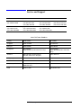
In This Manual…
•
•
•
•
•
•
Overview, page 1
Specifications, page 4
Initial Inspection and Shipping, page 5
Operation, page 7
Performance Tests, page 10
Connector Maintenance, page 24
779D Operating And Service Manual iii
Warranty
Custom systems are warranted by contractual agreement between Agilent
Technologies and the customer.
Certification
Agilent Technologies, Inc., certifies that this product met its published
specifications at the time of shipment from the factory. Agilent Technologies
further certifies that its calibration measurements are traceable to the
United States National Institute of Standards and Technology (NIST,
formerly NBS), to the extent allowed by the Institute’s calibration facility,
and to the calibration facilities of other International Standards
Organization members.
Warranty
This Agilent Technologies system product is warranted against defects in
materials and workmanship for a period corresponding to the individual
warranty periods of its component products. Instruments are warranted for a
period of one year. During the warranty period, Agilent Technologies will, at
its option, either repair or replace products that prove to be defective.
Warranty service for products installed by Agilent Technologies and certain
other products designated by Agilent Technologies will be performed at
Buyer’s facility at no charge within Agilent Technologies service travel
areas. Outside Agilent Technologies service travel areas, warranty service
will be performed at Buyer’s facility only upon Agilent Technologies’ prior
agreement and Buyer shall pay Agilent Technologies’ round trip travel
expenses. In all other areas, products must be returned to a service facility
designated by Agilent Technologies.
For products returned to Agilent Technologies for warranty service, Buyer
shall prepay shipping charges to Agilent Technologies and Agilent
Technologies shall pay shipping charges to return the product to Buyer.
However, Buyer shall pay all shipping charges, duties, and taxes for products
returned to Agilent Technologies from another country.
Agilent Technologies warrants that its software and firmware designated by
Agilent Technologies for use with an instrument will execute its
programming instructions when properly installed on that instrument.
Agilent Technologies does not warrant that the operation of the instrument,
or software, or firmware will be uninterrupted or error free.
LIMITATION OF WARRANTY. The foregoing warranty shall not apply
to defects resulting from improper or inadequate maintenance by Buyer,
Buyer-supplied software or interfacing, unauthorized modification or
misuse, operation outside of the environmental specifications for the
product, or improper site preparation or maintenance.
iv 779D Operating And Service Manual
NO OTHER WARRANTY IS EXPRESSED OR IMPLIED. AGILENT
TECHNOLOGIES SPECIFICALLY DISCLAIMS THE IMPLIED
WARRANTIES OR MERCHANTABILITY AND FITNESS FOR A
PARTICULAR PURPOSE.
EXCLUSIVE REMEDIES. THE REMEDIES PROVIDED HEREIN ARE
BUYER’S SOLE AND EXCLUSIVE REMEDIES. AGILENT
TECHNOLOGIES SHALL NOT BE LIABLE FOR ANY DIRECT,
INDIRECT, SPECIAL, INCIDENTAL, OR CONSEQUENTIAL
DAMAGES, WHETHER BASED ON CONTRACT, TORT, OR ANY
OTHER LEGAL THEORY.
YEAR 2000. Agilent Technologies warrants that each Agilent Technologies
hardware, software, and firmware product on Agilent Technologies’
Corporate Price List (dated July 1, 1998 or later) delivered under the
product’s contract of sale will be able to accurately process date data
(including, but not limited to, calculating, comparing, and sequencing) from,
into, and between the twentieth and twenty-first centuries, and the years
1999 and 2000, including leap year calculations, when used in accordance
with the product documentation provided that all other products (that is,
hardware, software, firmware) used in combination with such Agilent
Technologies product(s) properly exchange date data with it. If the
agreement requires that specific Agilent Technologies products must
perform as a system in accordance with the foregoing warranty, then that
warranty will apply to those Agilent Technologies products as a system, and
Customer retains sole responsibility to ensure the year 2000 readiness of its
information technology and business environment. The duration of this
warranty extends through January 31, 2001.
The remedies available under this warranty will be defined in, and subject to,
the terms and limitations of the warranties contained in the contract of sale.
To the extent permitted by local law, this warranty applies only to branded
Agilent Technologies products and not to products manufacture by others
that may be sold or distributed by Agilent Technologies. Nothing in this
warranty will be construed to limit any rights or remedies provided
elsewhere in the contract of sale with respect to matters other than year 2000
compliance.
Assistance
Product maintenance agreements and other customer assistance agreements
are available for Agilent Technologies products.
For assistance, call your local Agilent Technologies Sales and Service Office
(refer to “Service and Support” on page vi).
779D Operating And Service Manual v
Service and Support
Online assistance: www.agilent.com/find/assist
United States
(tel) 1 800 452 4844
Latin America
(tel) (305) 269 7500
(fax) (305) 269 7599
Canada
(tel) 1 877 894 4414
(fax) (905) 282-6495
New Zealand
(tel) 0 800 738 378
(fax) (+64) 4 495 8950
Japan
(tel) (+81) 426 56 7832
(fax) (+81) 426 56 7840
Australia
(tel) 1 800 629 485
(fax) (+61) 3 9210 5947
Europe
(tel) (+31) 20 547 2323
(fax) (+31) 20 547 2390
Asia Call Center Numbers
Country
Phone Number
Fax Number
Singapore
1-800-375-8100
(65) 836-0252
Malaysia
1-800-828-848
1-800-801664
Philippines
(632) 8426802
1-800-16510170 (PLDT Subscriber Only)
(632) 8426809
1-800-16510288 (PLDT Subscriber
Only)
Thailand
(088) 226-008 (outside Bangkok)
(662) 661-3999 (within Bangkok)
(66) 1-661-3714
Hong Kong
800-930-871
(852) 2506 9233
Taiwan
0800-047-866
(886) 2 25456723
People’s Republic of China
800-810-0189 (preferred)
10800-650-0021
10800-650-0121
India
1-600-11-2929
000-800-650-1101
vi 779D Operating And Service Manual
Safety and Regulatory Information
Review this product and related documentation to familiarize yourself with
safety markings and instructions before you operate the instrument. This
product has been designed and tested in accordance with international
standards.
WARNING
The WARNING notice denotes a hazard. It calls attention to a procedure,
practice, or the like, that, if not correctly performed or adhered to, could result
in personal injury. Do not proceed beyond a WARNING notice until the
indicated conditions are fully understood and met.
CAUTION
The CAUTION notice denotes a hazard. It calls attention to an operating
procedure, practice, or the like, which, if not correctly performed or adhered
to, could result in damage to the product or loss of important data. Do not
proceed beyond a CAUTION notice until the indicated conditions are fully
understood and met.
Instrument Markings
!
When you see this symbol on your instrument, you should refer to the instrument’s
instruction manual for important information.
This symbol indicates hazardous voltages.
The laser radiation symbol is marked on products that have a laser output.
This symbol indicates that the instrument requires alternating current (ac) input.
The CE mark is a registered trademark of the European Community. If it is
accompanied by a year, it indicates the year the design was proven.
The CSA mark is a registered trademark of the Canadian Standards Association.
1SM1-A
This text indicates that the instrument is an Industrial Scientific and Medical Group 1
Class A product (CISPER 11, Clause 4).
This symbol indicates that the power line switch is ON.
This symbol indicates that the power line switch is OFF or in STANDBY position.
779D Operating And Service Manual vii
Safety Earth
Ground
This is a Safety Class I product (provided with a protective earthing
terminal). An uninterruptible safety earth ground must be provided from the
main power source to the product input wiring terminals, power cord, or
supplied power cord set. Whenever it is likely that the protection has been
impaired, the product must be made inoperative and secured against any
unintended operation.
Before Applying Power
Verify that the product is configured to match the available main power
source as described in the input power configuration instructions in this
manual. If this product is to be powered by autotransformer, make sure the
common terminal is connected to the neutral (grounded) side of the ac power
supply.
viii 779D Operating And Service Manual
Typeface Conventions
•
Used to emphasize important information:
Use this software only with the 8494A/B, 8495A/B, 8496A/B.
•
Used for the title of a publication:
Refer to the 779D Operating And Service Manual.
•
Used to indicate a variable:
Type LOAD BIN filename.
Instrument Display
•
Used to show on-screen prompts and messages that you will see on the
display of an instrument:
The 8494A/B, 8495A/B, 8496A/B will display the message CAL1
SAVED.
[Keycap]
•
Used for labeled keys on the front panel of an instrument or on a
computer keyboard:
Press [Return].
{Softkey}
•
Used for simulated keys that appear on an instrument display:
Press {Prior Menu}.
User Entry
•
Used to indicate text that you will enter using the computer keyboard;
text shown in this typeface must be typed exactly as printed:
Type LOAD PARMFILE
•
Used for examples of programming code:
Italics
#endif // ifndef NO_CLASS
Path Name
•
Used for a subdirectory name or file path:
Edit the file usr/local/bin/sample.txt
Computer Display
•
Used to show messages, prompts, and window labels that appear on a
computer monitor:
The Edit Parameters window will appear on the screen.
•
Used for menus, lists, dialog boxes, and button boxes on a computer
monitor from which you make selections using the mouse or keyboard:
Double-click EXIT to quit the program.
779D Operating And Service Manual ix
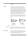
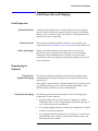
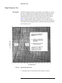
Overview
Description
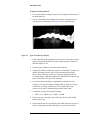
The 779D directional couplers are three-port passive devices for use in
7-mm, 50-ohm systems. A coupler is essentially a device for sampling
power flowing in one direction in a transmission line. Since no coupler is
perfect, some power flowing in the opposite direction is also sampled. The
rejection of power flowing in the unwanted direction is called directivity and
is the most important specification of a directional coupler. This coupler has
26 or 30 dB directivity, depending upon the frequency. Another specification
is the forward coupling (usually called just coupling) which is the fractional
amount of power transfer in the wanted direction. This coupler has a nominal
20 dB of coupling. These terms are defined in Figure 2, Coupler
Terminology. Figure 2 also shows a typical coupling curve. This is a typical
curve and not a specification. Table 1 contains the specifications.
The 779D is identified by its serial number found on the back plate (opposite
the nameplate). All correspondence with Agilent Technologies Sales/Service
offices in regard to this coupler should reference model 779D and this serial
number.
Figure 1
Manual Changes
Port Terminology
Connector Options
This manual provides complete information for any 779D with the serial
prefix 901, 922, 929, or 1144A. If your serial prefix is different, a yellow
change sheet should be supplied to adapt this manual to your serial prefix
coupler.
The two directly connected ports are known as the primary-line ports. Note
that these couplers are polarized, i.e., the input should be at the indicated
port. The third, coupled, port is known as the auxiliary port. These couplers
may be ordered with any combination of Type N (male or female)
connectors or APC-7 connectors on any or all ports.
779D Operating and Service Manual 1
Overview
Figure 2
779D Coupler Terminology
2 779D Operating and Service Manual
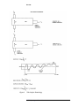
Overview
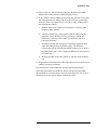
These couplers may be used in the measurement of reflection coefficient or
SWR over a very wide frequency range. Because of the wide frequency
range these couplers may also be useful as attenuators.
Figure 3
Coupling and Directivity Characteristics of the 779D Directional Coupler
779D Operating and Service Manual 3
Specifications
Specifications
Specifications for the 779D are shown in Table 1..
Table 1
Specifications
Characteristic
Value
Frequency range
1.7 to 12.4 GHz
Mean coupling
20 dB ±0.5 dB
Coupling variation
±0.75 dB
Directivity
>30 dB from 1.7 to 4.0 GHz
>26 dB from 4.0 to 12.4 GHz
SWR and Reflection Coefficient
Primary line
Auxiliary line
Insertion loss
<1.2 (0.091)
<1.2 (0.091)
<0.6 dΒ
Maximum power input
Primary line
Auxiliary line
50 W
0.5 W
Connectors
Input
Output
Auxiliary
Precision
Type N male
Type N female
Type N female
7-mm APC-71 connector on any or all ports(s)
on special order.
1. Registered trademark of Bunker Ramo Corporation
4 779D Operating and Service Manual
Initial Inspection and Shipping
Initial Inspection and Shipping
Initial Inspection
Mechanical Check
Electrical Check
Claims for Damage
If damage to the shipping carton is evident, ask that the carrier’s agent be
present when the instrument is unpacked. Inspect the parts for mechanical
damage, such as scratches or dents. Also check the cushioning material for
signs of severe stress (compacting).
The electrical performance should be verified as soon as possible after
receipt. Refer to the “Performance Tests” on page 10 for further instructions.
If there is mechanical damage or the coupler fails to meet electrical
specifications upon receipt, notify the carrier and your nearest Agilent
Technologies office immediately (a list of offices is at the end of this
operating note). Retain the shipping carton and the padding material for the
carrier's inspection.
Repackaging for
Shipment
Using Factory
Supplied Packaging
The same type containers and material used in factory packaging can be
obtained through the Agilent Technologies offices listed at the end of this
operating note.
If the coupler is being returned to Agilent Technologies for servicing, attach
a tag indicating the type of service required and the return address. Also
mark the container FRAGILE to assure careful handling.
Using Other Packaging
The following general instructions should be used for repackaging with
commercially available materials.
1. Wrap the coupler in heavy paper or plastic (if shipping to a Agilent
Technologies office or service center attach a tag indicating the type of
service required, and your return address).
2. Use a strong shipping container. A double-wall carton made of 2.4 MPa
(350 PSI) test material is adequate.
3. Use enough shock-absorbing material, 75 to 100 mm (3- to 4-inch layer)
around all sides of the coupler to provide firm cushioning and prevent
movement inside the container.
779D Operating and Service Manual 5
Initial Inspection and Shipping
4. Seal the shipping container securely.
5. Mark the shipping container FRAGILE to assure careful handling.
6 779D Operating and Service Manual
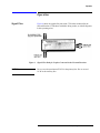
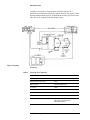
Operation
Operation
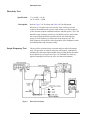
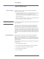
Signal Flow
Figure 4 shows the signal-flow path in the 779D when connected in the
forward direction (779D shown with label facing reader, as with all diagrams
in this operating note).
Figure 4
CAUTION
Signal Flow Path for Coupler Connected in the Forward Direction
Do not exceed a maximum RI50 W in the primary line. Do not exceed
0.5 W in the auxiliary line.
779D Operating and Service Manual 7
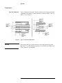
Operation
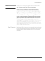
Connectors
Type N Connectors
Figure 5
CAUTION
Type N connectors used on the 779D are stainless steel for long wear and are
compatible with connectors whose dimensions conform to MIL-C-39012 or
MIL-C-71 (see Figure 5).
Type N Connector Dimension
Do not mate with Type N male connectors with a pin diameter RIgreater
than 0.0655 ", as a discontinuity producing excess SWR will be formed even
LIthe connector is not damaged.
8 779D Operating and Service Manual
Operation
APC-7 Connectors
Figure 6
Protect the face of the connectors from damage. Any scoring or burring of
the mating surfaces causes discontinuity; the resulting increase in SWR
degrades performance (see Service Note concerning APC-7 connectors
obtainable free from any Agilent Technologies sales/ service office). Do not
exceed the load limits given in Figure 6 for this type of connector.
APC-7 Connector Load Limits
CAUTION
Do not drop the coupler. While the coupler probably will not break, it can be
jarred out of adjustment and the connectors can be damaged.
Reflectometer
Measurements
Two 779D directional couplers connected together can be used with a sweep
oscillator for making broadband reflectometer measurements. In the
reflectometer, one coupler samples power going to the unknown while the
other samples power reflected from the unknown. When the couplers are
used with two Agilent 423A crystal detectors, swept-frequency
measurements of reflection coefficient versus frequency can be made easily.
The detected output of the reverse coupler is displayed by an output
indicator calibrated in reflection coefficient. For more information on
reflectometer techniques, request a copy of application Note 183, "High
Frequency Swept Measurement", obtainable free from any Agilent
Technologies office listed at the end of this operating note.
Power Leveling
With its broad frequency coverage, the 779D can be used in leveling
applications formerly requiring three or more couplers. When the 779D is
used with sweep oscillators, the power output is sampled at the auxiliary port
and detected with a crystal detector. The rectified detector voltage, when
applied to the sweep oscillator ALC input, maintains a constant RF power
level out of the main line of the directional coupler, within the flatness of the
coupling curve of the directional coupler.
779D Operating and Service Manual 9
Performance Tests
Performance Tests
Use the following procedure for initial electrical check, performance testing,
or whenever the coupler performance is suspected. Table 2 lists the
recommended test equipment. Other equipment may be substituted provided
its specifications equal or exceed the critical specifications. Table 3 provides
a place to record the results of the test. The coupler should be tested on a
swept-frequency basis to assure that there are no out-of-specification
narrow-frequency bands. If the results of the swept-frequency testing are
doubtful, or if the equipment for swept-frequency testing is not available, the
fixed-frequency test may be used. The performance tests should be
performed in the order given. Note that in many of these tests a 10-dB
attenuator is used in series with the flexible arm. This attenuator reduces
mismatch ambiguity by isolation. With the attenuator the mismatch is
reduced to approximately the mismatch of the attenuator which is lower than
the mismatch of the other components.
Table 2
Instrument
Sweep oscillator
Directional coupler
Recommended Test Equipment
Critical Specifications
Agilent Model No.
Frequency: band of interest
Power output: >10 mW
8620C mainframe with 886222B or 86290A
plug-ins
Frequency range: 1.7 to 12.4 GHz
779D
Directivity: >30 dB 1.7 to 4.0 GHz
>26 dB 4.0 to 12.4 GHz
Network analyzer
No other network analyzer will do
8410B/8411A/8413A
Slide load
Slides λ/2 at test frequency
SWR: <1.05
905A (1.8 to 18.0 GHz)
Oscilloscope with
swept-frequency indicator
Vertical Sensitivity: 1 dB/cm
Provision for storing trace bandwidth: variable to 30 kHz
Sweep and Blanking: compatible with sweep oscillator
181A/8755C
Reflection/transmission test unit
No other transmission/reflection test unit will do
8743A
Flexible arm
Frequency range: 1.7 to 12.4 GHz
SWR: <1.25
11605A
10 dB attenuator
Frequency range: 1.7 to 12.4 GHz
Attenuation: 10 dB (accuracy not important since used
for isolation)
8491A/B (Type N connector) Option 010
8492A (APC-7 connector) Option 010
X-Y recorder
Impedance: 200 K ohms/V
Sensitivity: 50 mV/in
7035A
Coaxial termination (2)
Impedance: 50 ohms
SWR: <1.1
909A Option 012 (Type N male)
909A Option 013 (Type N female)
909A Standard APC-7
Slotted-line sweep adapter**
Frequency: 1.8 to 12.4 GHz
448B*
10 779D Operating and Service Manual
Performance Tests
Table 2
Recommended Test Equipment
Instrument
Critical Specifications
Agilent Model No.
Slotted section **
Frequency: 1.8 to 12.4 GHz
Compatible with carriage
816A **
Carriage **
Holds slotted section
809C
BNC tee
BNC: 2 female thru 1 male
1250-0781 (UG-274A/U)
Oscilloscope
Vertical Sensitivity: >5 mV/cm
Bandwidth: 5 MHz
180C/1801A/1821A
Short
Connector: coaxial 7-mm
11511A (Type N female)
11512A (Type N male)
11565A (APC-7)
Modulator
On-off Modulator for 8755B
11665B
** Agilent Model 817B Swept Slotted Line system may be used instead of these items
Table 3
Performance Test Record
Tested by:
Date:
Dual-Directional Coupler:
Instrument Serial Number:
Directivity:
1.7 to 4.0 GHz
dB (>30 dB)
4.0 to 12.4 GHz
(dB (>26 dB)
Mean Coupling
dB (20 ± 0.5 dB)
Coupling variation
dB (±0.75 dB)
Coupling
Insertion Loss:
dB (<0.6 dB)
SWR (Reflection Coefficient)
Primary Line
<1.2 (0.091)]
Auxiliary Line
<1.2 (0.091)]
779D Operating and Service Manual 11
Performance Tests
Directivity Test
Specification
Description
1.7 to 4 GHz, > 30 dB
4 to 12.4 GHz, > 26 dB
Refer to Figure 7 for Test Setup and Table 4 for Test Equipment.
Directivity of a coupler is the ratio of power at the auxiliary port with
coupler in forward direction to power at the auxiliary port with coupler in
reverse direction (coupler terminated each time and same power). The 779D
should be swept-frequency tested to be sure that there are no narrow-band
out-of-specification points that would be missed with fixed-frequency
testing. A fixed-frequency test follows the swept-frequency test. The
fixed-frequency test should be used at frequencies where ambiguous results
are obtained with swept-frequency testing.
Swept-Frequency Test
Figure 7
This test will be performed using a network analyzer and a reflectometer
setup. The procedure is similar to using any reflectometer; calibration by
returning all of the output signal and then using a sliding load to determine
the true directivity (see Application Note 183, obtainable free from any
Agilent Technologies sales/service office, for further information).
Directivity Test Setup
12 779D Operating and Service Manual
Performance Tests
Table 4
Procedure
Directivity Test Equipment
Equipment:
Model Number
Sweep oscillator
8620C/86222B/86290A
Directional coupler
779D
Harmonic frequency converter
8411A
Network analyzer
8410B with 8413A plug-in
Oscilloscope
180C/1801A/1821A
Flexible arm
11605A
10 dB attenuator
8492A
Short
11511A (Type N female)
11512A (Type N male)
11565A (Type APC-7)
Sliding load
905A
1. Connect the equipment as shown in Figure 7.
2. Set the oscilloscope sensitivity to 50 mV/cm.
3. Adjust the network analyzer to get an amplitude trace on the
oscilloscope.
4. Open (1) and short (2) the 779D under test. Take the average of the
traces as the calibration trace. Mark the trace on the CRT with a grease
pencil. If a short is not available use just the open circuit trace.
5. Connect a sliding load (3) to the 779D under test.
6. Increase the network analyzer test channel gain by 30 dB (1.7 to 4 GHz)
or 26 dB (4 to 12.4 GHz).
7. Run a slow trace while rapidly phasing the sliding load over at least λ/2.
The average of the traces should be below the grease pencil line at all
frequencies. If not, proceed with the following.
779D Operating and Service Manual 13
Performance Tests
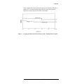
Single-Frequency Test
Description
Figure 8
The following single-frequency test will enable you to find the true value of
directivity. A sliding load is used and both the maximum indication (where
the voltage reflected from the load adds to the directivity signal) and the
minimum indication (where the voltage reflected from the load subtracts
from the directivity signal) are determined. Entering these values in
Figure 8, Signal Separation Chart, will enable you to determine the true
directivity. With a good load this should be close to the average reading. The
corrected directivity reading should be less than the directivity specification
at the frequency tested.
Signal Separation Chart
8. Manually set the sweep oscillator to the frequency of interest.
14 779D Operating and Service Manual
Performance Tests
9. Remove the sliding load and set the open (1) and short (2) readings on
the 8413A meter equally spaced around zero using the most sensitive
scale.
10. Replace the sliding load and increase the gain as in step f above.
11. Observe amplitude meter readings while phasing sliding load.
12. To find the true value of directivity subtract the two readings (for
example, 34 dB - 31 dB = 3 dB). Enter the following signal separation
chart on the vertical scale at 3 dB, read over to the curve and drop down
to the value of M2 = 1.25 dB. Add this correction to the lowest numerical
reading (31 + 1.25 dB = 32.25 dB) as the true reading. This reading
should be greater than the directivity specification at that frequency.
NOTE
Only the left-hand curve (e load > e unknown) be consulted since, with a good
load (SWR < 1.06), the unknown voltage being measured will be greater
than the voltage reflected from the load.
13. Repeat the above measurement at all frequencies of interest.
Coupling Test
Specification
Description
Mean coupling, 20 dB ±0.5 dB
Coupling variation, ±0.75 dB.
Refer to Figure 9 for Test Setup and Table 5 for Test Equipment.
779D Operating and Service Manual 15
Performance Tests
Coupling is measured by first calibrating a network analyzer for a
transmission measurement without the coupler inserted. The coupler is then
inserted and the amount of power coupled out the auxiliary port is measured.
This value is the coupling of the directional coupler.
Figure 9Coupling
Test Setup
Table 5
Coupling Test Equipment
Equipment
Model Number
Sweep oscillator
8620C/86222B/86290A
Reflection-transmission test unit
8743A
Network analyzer
8410B with 8413A plug-in
X-Y recorder
7035B
Harmonic frequency converter
8411A
Flexible arm
11605A
10 dB attenuator
8492A
Coaxial termination
909A Option 012 (Type N male)
909A Option 013 (Type N female)
090A Standard (APC-7)
16 779D Operating and Service Manual
Performance Tests
Procedure
To calibrate for the coupling test:
1. Connect the equipment as shown inFigure 9, Coupling Test Setup.
2. Connect the two ports of the 8743A together DVshown for
"CALIBRATE" with a 10-dB attenuator (see “Performance Tests” on
page 10 introduction). If any adapters will be necessary later in the test
to connect the 779D under test, the adapters should be inserted now so
that their insertion loss will be calibrated out.
3. Tune sweep oscillator manually throughout its entire frequency band
without recording to be sure the X-Y recorder will remain on-scale
throughout the entire frequency range. Do not reduce the sensitivity
much below about 100 mV/inch since the output of the 8413A is 50
mV/dB and 0.5 dB must be resolved. The sensitivity may be increased if
the trace will still stay on-scale.
4. Record a reference line on the X-Y recorder across each frequency band
and mark this trace 20 dB. Record the value of network analyzer test
channel gain for future use.
5. Record two traces that represent limits of acceptable coupling variations
as follows:
a. Increase the test channel gain 1 dB and run a line.
b. Decrease the test channel gain 2 dB (1 dB less than the reference
line) and run a line.
To perform a coupling test:
1. Detach the flexible arm at the unknown port of the 8743A and insert the
779D under test, as shown for "MEASURE." Detach at the end of the
10-dB attenuator connected to the unknown port.
2. Increase the test channel gain 20 dB from the setting in step d and record
a trace.
3. Sweep each band and record the trace until the entire frequency range
from 1.7 to 12.4 GHz has been covered.
4. Measuring from the 20-dB line recorded in step d and using the limit
lines as ±1 dB calibrations, find the highest point and lowest point on the
measurement traces.
a. Highest + Lowest / 2 = Mean coupling
b. Highest – Lowest / 2 = Coupling variation
Insertion Loss Test
Specification
<0.6 dB
779D Operating and Service Manual 17
Performance Tests
Description
Figure 10
Table 6
Refer to Figure 10 for Test Setup and Table 6 for Test Equipment. The
insertion loss specification includes the loss in the coaxial line plus the
coupling loss. A network analyzer is used to measure transmission loss
without and with the coupler inserted. The difference is the insertion loss.
Insertion Loss Test Setup
Insertion Loss Test Equipment
Equipment:
Model Number
Sweep oscillator
8620C/86222B/86290A
Reflection-transmission test unit
8743A
Network analyzer
8410B with 8413A plug-in
Harmonic frequency converter
8411A
Flexible arm
11605A
10 dB attenuator
8492A Option 010
Coaxial termination
909A Option 012 (Type N male)
909A Option 013 (Type N female)
090A Standard (APC-7)
18 779D Operating and Service Manual
Performance Tests
Procedure
To calibrate for insertion loss:
1. Connect the equipment as shown in Figure 10.
2. Connect a 10-dB attenuator, such as the Agilent 8492A Option 10, to the
11605A Flexible Arm (see Power Leveling), and connect the attenuator
to the 8743A unknown port. Include any adapters necessary to later
connect the 779D under test. This will cancel out the loss of the
adapters.
3. Set the sweep oscillator to sweep the desired band. Adjust 8410E for a
stable display over the entire band being swept.
4. Dc couple and dc-balance the oscilloscope vertical amplifier. Adjust the
oscilloscope to display the amplitude output from the 8413A. Set the
display for 10 mV/cm sensitivity.
5. Set the trace approximately two centimeters from the top of the screen.
Draw the trace on the screen of the oscilloscope with a grease pencil.
6. Decrease the 8410B test channel gain by 1 dB. The trace on the
oscilloscope should drop exactly 5 centimeters. This checks the
calibration of, the oscilloscope. If the trace does not drop exactly 5 cm
with 10 mV/cm sensitivity, set the oscilloscope vertical gain vernier for
exactly 5 cm vertical deflection.
7. Go back to the original setting on the 8410B. Drop the trace down 3 cm
= 0.6 dB. Do this by noting the value where the trace crosses the center
vertical graticule line. Then, with the 8410B amplitude vernier control
move the trace down exactly 3 cm. Draw this trace with a grease pencil.
Reset the trace to top grease pencil line with the 8410B amplitude
vernier control.
To perform an insertion loss:
Since we have two insertion-loss limit lines drawn we can now insert the
primary line of the 779D and see if it falls within these limit lines. If it does,
the 779D is within insertion-loss specifications. Proceed as follows:
1. Open the flexible arm between the unknown port and the 10-dB
attenuator (or between adapters, if used) and insert the primary line of
the 779D as shown for "TEST." Be sure to support the weight of the
779D independently.
2. The trace on the oscilloscope should be between the two grease pencil
lines on the CRT for the 779D to be within specifications. If not, check
the connectors and especially the connector faces.
779D Operating and Service Manual 19
Performance Tests
SWR (Reflection
Coefficient) Test
Specification
Description
Primary line < 1.2 (0.091)
Auxiliary line < 1.2 (0.091)
Refer to Figure 11 for Test Setup and Table 7 for Test Equipment.
SWR (reflection coefficient) is measured with a swept slotted-line system.
This system enables the SWR to be measured on a swept-frequency basis so
that there are no narrow-band out-of-specification frequencies which could
be missed with spot single-frequency testing. SWR is measured using a
storage oscilloscope and while moving the probe in the slotted-line section.
This procedure moves the indication through all possible phases so that the
maximum SWR may be measured.
Figure 11
SWR Test Setup
20 779D Operating and Service Manual
Performance Tests
Table 7
SWR Test Equipment
Equipment
Model Number
Sweep oscillator
8620C/86222B/86290A
Slotted-line sweep adapter*
448B
Carriage*
809C
BNC tee
1250-0781 (UG-274A/U)
Oscilloscope
180C/1801A/1821A
Sliding load
905A
Swept frequency indicator
182T/8755C
Slotted line *
816B
Coaxial termination
909A Option 012 (Type N male)
909A Option 013 (Type N female)
090A Standard (APC-7)
Modulator
11665B
*These items are be obtained as the Agilent 817B Swept Slotted Line System.
Procedure
To perform a Power Leveling:
1. Connect the equipment as shown in Figure 11.
2. Set sweep oscillator to sweep desired band.
3. Level the output of the sweep oscillator as instructed in the operating
instructions for the swept slotted-line system. Note that, due to the
extremely wide frequency range of the swept-slotted line system, the RF
output may vary widely even though the input is leveled. This occurs
because the efficiency of both probes drops off at the lower frequencies.
Since leveling is controlled by the do voltage developed by’ the leveling
probe, this voltage will depend upon the efficiency of the probe pickup.
However, by matching the characteristics of both probes and using them
as a matched pair the output variation can be held to approximately 3
dB.
779D Operating and Service Manual 21
Performance Tests
To perform a Measurement:
1. Set sweep oscillator for single-frequency (CW) operation at the center of
the band under test.
2. Locate a maximum in the standing-wave pattern. A maximum is the
widest portion of the display (see Figure 12 for a typical display).
Figure 12
Typical Oscilloscope Display
3. If the slotted-line probe penetration has not been set, loosen the carriage
probe by turning the knurled lock in the carriage and move the probe
until the output is 5 mV.
4. Set the sweep oscillator to sweep the band of interest.
5. Temporarily connect oscilloscope to probe on slotted line. To make sure
that the maximum picked in step b is the maximum in the display,
observe the oscilloscope on the 5 mV/cm range, adjusting probe for
1-cm high display. Tighten the knurled lock. The position of the carriage
probe is now correct for square-law operation.
6. Set swept-frequency indicator to logarithmic mode and move the
carriage over at least one-half wavelength while viewing on a storage
oscilloscope (if storage oscilloscope is not available take a time
exposure of the trace). Read maximum width of trace in dB.
7. Compute the voltage ratio using the formula:
a. SWR = log–1 (dB/20) or 1.2 SWR = 1.58 dB.
8. If the sweep rate is too high, some of the fine structure of the SWR
pattern may be lost.
9. If the results do not meet specification, the width of the trace may be at
fault. To compensate for the width of the trace, proceed as follows.
22 779D Operating and Service Manual
Performance Tests
10. Observe the trace with the carriage stationary. Read the trace-width.
Subtract this reading from the reading obtained in step 6.
11. If the results are still not within specifications, the reflection vector from
the termination may be adding in-phase to the reflection vector being
measured. These two signals can be resolved by using a sliding load as
the termination as follows.
a. With the above setup, set the sweep oscillator to CW on a single
frequency under question.
b. Adjust the slotted-line carriage position and the sliding load for
maximum vertical deflection on the oscilloscope. Adjust the
oscilloscope vertical position control to position the spot for a
convenient reference.
c. Position the slotted-line carriage for a minimum voltage and then
adjust the sliding load for maximum voltage. The difference
between the position of the dot now and the reference set in step b is
the SWR in dB of the 779D. Compute the SWR in the same manner
as given in step 7.
d. Measure the SWR in the same manner as with the swept-frequency
test.
12. Repeat the measurement on the other ports. Be sure to keep all ports not
under test properly terminated.
For a discussion of swept-slotted line systems and other information
concerning this method see Stephen F. Adam, "Swept-Frequency SWR
Measurements in Coaxial Systems," Hewlett-Packard Journal, Vol. 18 No. 4,
obtainable from your nearest Agilent Technologies office.
779D Operating and Service Manual 23
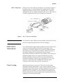
Connector Maintenance
Connector Maintenance
APC-7 Connectors
Directional couplers with APC-7 connectors should be handled with
particular care for two reasons:
1. Continuity through APC-7 connectors is obtained by end-to-end contact
of the inner and outer conductors. Consequently, the electrical
performance of the connector is largely dependent upon the condition of
these exposed surfaces.
2. The inner conductor of the APC-7 connector is connected directly to the
inner coaxial conductor of the directional coupler.
CAUTION
Any twisting force on this inner conductor may throw the directional coupler
out RIspecifications.
The part of an APC-7 connector that is most likely to be damaged is the
inner conductor contact. Since it protrudes slightly beyond the plane of
electrical contact, any wiping action of one conductor across the other can
damage the contact enough to cause a discontinuity. If damage is suspected,
examine the contact with a magnifying glass and push lightly with the eraser
on the end of a pencil. As the pressure is released the contact’s spring action
should cause it to move outward. If not, the contact is defective. Replace as
follows:
Contact Replacement
Replacement inner conductor contacts are available from Agilent (part
number 1250-0907, Check Digit 8), and from Amphenol RIF Division,
Danbury, Connecticut (part number 131-129). When ordering from Agilent
Technologies also request the Service Note concerning 7-mm connectors for
further information.
The important precautions that apply to the replacement of inner conductor
contacts are these:
1. Do not disassemble the connector.
2. Do not apply more than slight inward pressure to the inner conductor.
3. Do not apply any twisting force to the inner conductor.
4. Do not attempt to repair contacts.
5. Do not reuse contact.
24 779D Operating and Service Manual
Connector Maintenance
CAUTION
Inward pressure or twisting force applied to the inner conductor RIthe
APC-7 connector can throw the 779D out-of-specifications.
Because of the above considerations, contact removal should not be
attempted with ordinary hand tools. Only the Agilent self-positioning,
hypodermic-action contact extractor tool (part number 5060-0236, Check
Digit 7) part of ACP-7 Connector Tool Kit 11591A, should be used. This
tool exerts no appreciable inward pressure and no twisting force on the inner
conductor. Instructions for removing contacts are supplied with the tool.
No tool is required for installing a replacement contact. Insert the contact
gently by hand, applying only enough inward pressure to snap it in place.
Then check for proper installation by inspecting the contact with a
magnifying glass for even spacing of its four segments. Also, test for normal
spring-action by applying light inward pressure against the end of the
contact with an eraser at the end of a pencil. As the pressure is released the
contact’s spring-action should cause it to move outward. If not, the contact is
defective. Replace with another contact.
Type N Connectors
Replacement of Type N connectors is not recommended, since just loosening
the outer shell mounting screws may throw the coupler out of specifications.
Return the coupler to Agilent Technologies office if a Type N connector
needs repair.
779D Operating and Service Manual 25