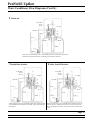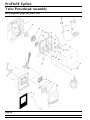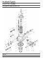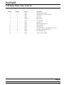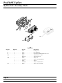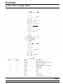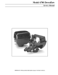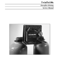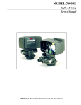
1
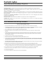
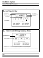
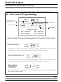
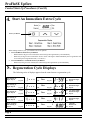
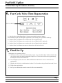
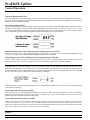
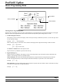
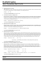
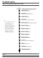
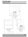
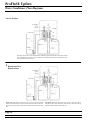
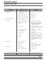
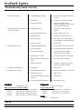
ProFloSE
Upflow Brining
Service Manual
IMPORTANT: Fill in pertinent information on page 2 for future reference.
ProFloSE Upflow
Job Specification Sheet
Job Number ___________________________________
Model Number ________________________________
Water Test ____________________________________
Capacity Of Unit ________________________ Max. _____________ Per Regeneration
Mineral Tank Size: Diameter ___________________ Height _____________________
Under Bedding ____________________________ Amount _______________________
Type Of Media ____________________________ Cubic Feet _____________________
Brine Tank Size ________________________________
Salt Setting Per Regeneration ________________________________
Valve Programming
Treated Water Capacity ______________________________ (Gallons / Liters/m3)
Regeneration Day Override _______________________________ (Max. Days Between Regen.)
Regeneration Time ________________________________ ( A.M. ) ( P.M. )
Notes:
________________________________________________________________________________
________________________________________________________________________________
________________________________________________________________________________
________________________________________________________________________________
________________________________________________________________________________
________________________________________________________________________________
________________________________________________________________________________
Page 2
Printed in U.S.A.
ProFloSE Upflow
General Residential Installation Check List
WATER PRESSURE: A minimum of 20 psi inlet water pressure is required for regeneration valve to operate effectively
ELECTRICAL FACILITIES: An uninterrupted alternating current (A/C) supply is required. Please make sure your voltage
supply is compatible with your unit before installation.
EXISTING PLUMBING: Condition of existing plumbing should be free from lime and iron buildup. Piping that is built up
heavily with lime and/or iron should be replaced. If piping is clogged with iron, a separate iron filter unit should be installed ahead
of the water softener.
LOCATION OF SOFTENER AND DRAIN: The softener should be located close to a clean working drain and connected
according to local plumbing codes.
BY-PASS VALVES: Always provide for the installation of a by-pass valve if unit is not equipped with one.
CAUTION: Water pressure is not to exceed 120 p.s.i., water temperature is not to exceed 110°
subjected to freezing conditions.
F, and the unit cannot be
Valve Installation and Start-up Procedures
INSTALLATION INSTRUCTIONS
1.
Place the softener tank where you want to install the unit, making sure the tanks are level and on a firm base.
2.
All plumbing should be done in accordance with local plumbing codes. The pipe size for the drain line should be a minimum
of 1/2″. Backwash flow rates in excess of 7 gpm or length in excess of 20´ require 3/4″ drain line.
3.
The 1″ distributor tube (1.050 O.D.) should be cut flush with top of tank.
4.
Lubricate the distributor o-ring seal and tank o-ring seal. Place the main control valve on tank. Note: Only use silicone
lubricant.
5.
Solder joints near the drain must be done prior to connecting the Drain Line Flow Control fitting (DLFC). Leave at least 6″
between the DLFC and solder joints when soldering pipes that are connected on the DLFC. Failure to do this could cause
interior damage to the DLFC.
6.
Teflon tape is the only sealant to be used on the drain fitting.
7.
Make sure that the floor is clean beneath the salt storage tank and that it is level.
8.
On units with a by-pass, place in by-pass position. Turn on the main water supply. Open a cold soft water tap nearby and let
run a few minutes or until the system is free from foreign material (usually solder) that may have resulted from the installation.
Once clean, close the water tap.
9.
Place the by-pass in service position and let water flow into the mineral tank. When water flow stops, slowly open a cold water
tap nearby and let run until the air is purged from the unit.
10. Plug unit into an electrical outlet. Note: All electrical connections must be connected according to local codes.
11. Add water to the top of the air check. Manually step the valve to the Brine Draw Position and allow the valve to draw water
from the brine tank until it stops. Note: The air check will check at approximately the midpoint of the screened intake area.
12. Next, manually step the valve to the Brine Refill Position and allow the valve to return to Service automatically.
13. With the valve in Service, check that there is about 1.0″ of water above the grid in the brine tank, if used.
14. Fill the brine tank with salt.
15. Set-Up is now finished, the control can now be left to run automatically.
Page 3
Printed in U.S.A.
ProFloSE Upflow
Control Start-Up Procedures
Whenever the valve is in Service the current time of day can be set, the control programmed, or an extra regeneration initiated at
any time.
1.
Set Time Of Day
Service Indicator:
Flow Indicator:
Valve In Service - Dot On
Extra Cycle Tonight - Flashing Dot
Flashing Dot With Water Flow
P.M. Indicator
Set Up Button
Set Down Button
2.
Enter Control Programming Mode
Program Mode Indicator:
Program Mode Entered - Dot On
Extra Cycle Button
1.
Push and hold for 5 seconds both the Up and Down Set Buttons to enter Programming Mode.
2.
Push the Extra Cycle Button once per display until all have been viewed and this mode is exited and normal operation is
resumed.
Page 4
Printed in U.S.A.
ProFloSE Upflow
Control Start-Up Procedures (Cont’d.)
Depending on current control programming, option setting displays that are not required to be set will not be viewed.
3.
Set Control Programming
Program Mode Indicator:
Program Mode Entered - Dot On
Set Up Button
Extra Cycle Button
Set Down Button
1.
The first option setting display that appears in the Program Mode is Treated Water Capacity. Using the Set Up or Down
Buttons, set the amount of treated water that can flow through the unit before a regeneration is required. For Example:
2.
Push the Extra Cycle Button. The second option setting display that appears is Regeneration Time. Using the Set Up or
Down Buttons, set the desired time of day when a regeneration can occur, if required. For Example:
3.
Push the Extra Cycle Button. The third option setting display that appears is Regeneration Time. Using the Set Up or
Down Buttons, set the maximum number of days b3efore a regeneration cycle must occur. For Example:
4.
Control programming is now complete. Push the Extra Cycle Button. This will exit the control from the Programming
Mode, and resume Normal Operation.
Page 5
Printed in U.S.A.
ProFloSE Upflow
Control Start-Up Procedures (Cont’d.)
4.
Start An Immediate Extra Cycle
Extra Cycle Button
When starting an Extra Cycle, you will have one or two options:
1.
Press and Release the Extra Cycle Button:
- With Immediate Regeneration controls the control will go into regeneration cycle immediately.
- With Delayed Regeneration controls the Service Arrow will begin to flash immediately and a regeneration will
occur at the present regeneration time (i.e. 2:00 a.m.)
2.
Press and Hold for 5 seconds the Extra Cycle Button:
- With Delayed Regeneration controls, the control will go into regeneration cycle immediately.
5.
Regeneration Cycle Displays
The following series of displays appear when the control enters a regeneration cycle:
Valve Driving To
Regen. Step #1
Valve Driving To
Regen. Step #2
Valve Driving To
Regen. Step #3
Valve Driving To
Regen. Step #4
Regen. Complete.
Valve Driving To
Service
Service
Flow
Service
Flow
Program
P.M.
Service
Flow
Program
P.M.
Service
Flow
Program
P.M.
Service
Flow
Program
P.M.
Service
Flow
Program
P.M.
Then
Program
P.M.
Service
Flow
Then
Program
P.M.
Service
Flow
Program
P.M.
Service
Flow
Then
Then
Program
P.M.
Service
Flow
Then
Program
P.M.
Page 6
Printed in U.S.A.
Less Than 60 Min.
Remain In Regen.
Step #1
Less Than 10 Min.
Remain In Regen.
Step #2
Less Than 10 Min.
Remain In Regen.
Step #3
Less Than 12 Min.
Remain In Regen.
Step #4
Valve Has
Returned To
Service
ProFloSE Upflow
Control Start-Up Procedures (Cont’d.)
6.
Fast Cycle Valve Thru Regeneration
Extra Cycle Button
A. Once the valve reaches Regen Step #1 let water run to drain for about 5 minutes.
Next, manually step the valve through a regeneration cycle checking valve operation in each step:
B. Push the Extra Cycle Button once to advance the valve to Regen Step #2.
C. Push the Extra Cycle Button once to advance the valve to Regen Step #3. (Optional)
D. Push the Extra Cycle Button once to advance the valve to Regen Step #4. (Optional)
E. Push the Extra Cycle Button once more to advance the valve back to Service.
7.
Final Set-Up
With proper valve operation verified:
A. Add water to the top of the air check. Manually step the valve to the Brine Draw Position and allow the
valve to draw water from the brine tank until it stops. Note: The air check will check at approximately
the midpoint of the screened intake area.
B. Next, manually step the valve to the Brine Refill Position and allow the valve to return to Service
automatically.
C. With the valve in Service, check that there is about 1.0″ of water above the grid in the brine tank, if used.
D. Fill the brine tank with salt.
E. Set-Up is now finished, the control can now be left to run automatically.
Page 7
Printed in U.S.A.
ProFloSE Upflow
Control Operation
Timeclock Regeneration Valves
In normal operation the Time Of Day Display will be viewed at all times. The control will operate normally until the number of
days since the last regeneration reaches the Regeneration Day Override setting. Once this occurs, a regeneration cycle will then be
initiated at the preset Regeneration Time.
Flow Meter Equipped Valves
In normal operation the Time Of Day Display will alternate being viewed with a Volume Remaining Display. This display will be
in gallons. As treated water is used, the Volume Remaining Display will count down from a maximum value to zero or (----). Once
this occurs a regeneration cycle will then be initiated immediately or delayed to the set Regeneration Time. Water flow through the
valve is indicated by the Flow Dot that will flash in a direct relationship to flow rate. For Example:
Immediate Regeneration Valves With Days Between Regeneration Override Set
When the valve reaches its set Days Since Regeneration Override value a regeneration cycle will be initiated immediately. This
event occurs regardless of the Volume Remaining display having reached zero gallons.
Delayed Regeneration Valves With Days Between Regeneration Override Set
When the valve reaches its set Days Since Regeneration Override value a regeneration cycle will be initiated at the preset
Regeneration Time. This event occurs regardless of the Volume Remaining display having reached zero gallons.
Control Operation During Regeneration
In Regeneration the control will display a special Regeneration Display. In this display the control will show the current
regeneration step number the valve is advancing to, or has reached, and the time remaining in that step. The step number displayed
will flash until the valve has completed driving to this regeneration step position. Once all regeneration steps have been completed
the valve will return to Service and resume normal operation. For Example:
Pushing the Extra Cycle Button during a regeneration cycle will immediately advance the valve to the next cycle step position and
resume normal step timing.
Control Operation During Programming
The control will only enter the Program Mode with the valve in Service. While in the Program Mode the control will continue to
operate normally monitoring water usage and keeping all displays up to date. Control programming is stored in memory
permanently, without the need for battery backup power.
Control Operation During A Power Failure
During a power failure all control displays and programming will be stored for use upon power re-application. The control will
retain these values for years, if necessary, without loss. The control will be fully inoperative and any calls for regeneration will be
delayed. The control will upon power re-application resume normal operation from the point were it was interrupted. An indication
that a power outage has occurred will be an inaccurate time of day display.
Page 8
Printed in U.S.A.
ProFloSE Upflow
Master Programming Mode
Set Up Button
Extra Cycle Button
Set Down Button
Entering Master Programming Mode
With the Time of Day Display set to 12:01 P.M., push and hold for 5 seconds both the Set Up and Set Down Buttons. The Program
Indicator will turn on to signal that this mode is entered. In this mode all possible option settings may be viewed.
1. US/Metric Display Format (U)
This display is used to set the desired display format. This option setting is identified by the letter (U) in the first digit. There
are three possible settings:
Example:
[ U - - 1 ] for US gallons
Metric format uses liters or cubic meters with a 24-hour timekeeping format. Regeneration timing in tenths of minutes.
Example:
[ U - - 2 ] for liters
[ U - - 4 ] for cubic meters
The SET UP or DOWN buttons will adjust this value.
Depress the Extra Cycle Button to proceed to the next step.
2.
Regeneration Type (7)
Depress the Extra Cycle Button. This display is used to set the Regeneration Type. This option setting is identified by the
number 7 in the first digit. There are 3 possible settings:
Timeclock Delayed. The control will determine that regeneration is required when the set Regeneration Time has been
reached. The Regeneration Day Override setting will determine which days a regeneration cycle will be initiated.
Example:
[7--1]
Meter Immediate. The control will determine that regeneration is required when the available volume of softened water drops
to or below zero. Regeneration to begin immediately.
Example:
[7--2]
Page 9
Printed in U.S.A.
ProFloSE Upflow
Master Programming Mode (Cont’d.)
2.
Regeneration Type (7) (Cont’d.)
Meter Delayed. The control will determine that a regeneration is required when the available volume of softened water drops
to or below zero. Regeneration is to begin immediately at the set Regeneration Time.
Example:
[7--3]
The Set UP and DOWN Buttons will adjust this value.
3.
Treated Water Capacity (No Display Code)
Depress the Extra Cycle Button. This display is used to set the amount of treated water (gallons/liters) that can be produced by
the unit before a regeneration cycle is required. With Meter Delayed Regeneration Type set, it will be up to the programmer to
determine a reserve capacity and subtract that value from the calculated full capacity of the unit. This display will not be
viewed with Timeclock Regeneration Type set.
Example:
Regenerates every 700 gallons or liters - [
700]
The Set UP and DOWN Buttons will adjust this value.
4.
Regeneration Time (No display Code)
Depress the Extra Cycle Button. The next display viewed is the option setting for Regeneration Time. It is identified by a nonflashing colon between two sets of numbers. Set the desired time of day that a regeneration may occur, if required. This display
will not be viewed with Meter Immediate Regeneration Type set.
Example:
2 o’clock A.M. regeneration time - [
2 : 0 0 ] (A.M. Indicator Dot On)
The Set UP and DOWN Buttons will adjust this value.
5.
Regeneration Day Override (A)
Depress the Extra Cycle Button. This display is used to set the maximum amount of time (in days) the unit can be in service
without a regeneration. This option setting is identified by the letter ‘A’ in the first digit. With Meter Immediate Regeneration
Type selected, regeneration will begin at the same point in time some amount of days ago when the last regeneration cycle was
initiated. With Timeclock or Meter Delayed Regeneration Types selected, regeneration begins at the set Regeneration Time.
An OFF setting will cancel this feature with all regeneration types except Timeclock Regeneration were it must be used.
Example:
Override every 7 days
-
Cancel setting -
[A--7]
[ A O F F ] (Meter Immediate or Delayed Regeneration Types Only)
The Set UP and DOWN Buttons will adjust this value.
6.
Regeneration Cycle Step Programming (1) (2) (3) (4) (5) (6)
Depress the Extra Cycle Button. The next 2-4 displays viewed are part of a series of option settings used to program the
Regeneration Cycle. Up to 4 steps can be programmed. Each display is used to set the duration time in minutes (or tenths of
minutes - Metric) of that specific step in a regeneration cycle. A step # will turn on for the regeneration cycle step being
programmed. Regeneration steps are skipped by setting the display to 0 and regeneration ended by setting the step # after the
last active step to OFF, as shown below and on the next page:
Examples:
Example:
Regeneration Cycle Step #1 - 8 minutes
-
[1--8]
Regeneration Cycle Step #3 - skipped
-
[3--0]
lbs. salt ÷ 3 ÷ B.L.F.C. Size = refill time in minutes, 10 lbs. salt ÷ 3 ÷ .25 = 13.3 minute refill
The Set UP and DOWN Buttons will adjust these values.
Page 10
Printed in U.S.A.
ProFloSE Upflow
Master Programming Mode (Cont’d.)
7.
Flow Meter Size (F)
Depress the Extra Cycle Button. The next display is used to set the flowmeter size. This option setting is identified by the letter
F in the first digit. In this display set the proper amount of pulses generated by the flow meter for each gallon or liter of water
flow. This setting will not be viewed with Timeclock Regeneration Type selected.
Examples:
[ F 1 3 1 ] 3/4″ Turbine Flow Meter (US Format)
[ F 3 4.6 ] 3/4″ Turbine Flow Meter (Metric Format)
The Set UP and DOWN Buttons will adjust this value.
8.
Valve Type (o)
Depress the Extra Cycle Button. This display is used to set the type of valve used with the control. This option setting is
identified by the letter o in the first digit. There are two possible selections with #1 being the required setting.
Examples:
[ o - - 1 ] ProFloSE Valve Operation
[ o - - 2 ] Option Not Typically Used
The Set UP and DOWN Buttons will adjust this value.
9.
Line Frequency (LF)
Depress the Extra Cycle Button. This display is used to set the frequency of the power applied to the control. When properly
set, all timekeeping functions will remain accurate. This option setting is identified by the letters LF in the first digit. There are
two possible selections.
Examples:
[ L F 5 0 ] 50Hz Line Frequency Operation
[ L F 6 0 ] 60Hz Line Frequency Operation
The Set UP and DOWN Buttons will adjust this value.
Exiting This Option Setting Level
Push the Extra Cycle Button once per display until all have been viewed. The Program Mode will be exited and normal operation
resumed.
Resetting Permanent Programming Memory Push and hold the Set Up and Down Buttons for 25 seconds or until the Time Of Day Display resets to 12:00 P.M. All option
setting will then reset to the default values. Control programming will then have to be reset as necessary.
Page 11
Printed in U.S.A.
ProFloSE Upflow
Master Programming Mode Flow Chart
Note:
1.
Set Time Of Day Display To 12:01 P.M.
2.
Push And Hold The Set Up And Set
Down Button For 5 Seconds.
3.
Push Extra Cycle Button Once Per
Display Until All Displays Are Viewed
And Normal Operation Is Resumed.
4.
Option Setting Displays May Be
Changed As Required By Pushing
Either The Set Up Or Down Button.
5.
Depending On Current Valve
Programming Certain Displays Will
Not Be Able To Be Viewed Or Set.
Page 12
Printed in U.S.A.
ProFloSE Upflow
Dimensional Drawing
Page 13
Printed in U.S.A.
ProFloSE Upflow
Water Conditioner Flow Diagrams
Service Position
Hard water enters unit at valve inlet and flows around the piston down thru the mineral in the mineral
tank. Conditioned water enters center tube thru the bottom distributor then flows up thru the center
tube and to the outlet of the valve.
1 Brine Draw/Slow
Rinse Position
Brine. Hard water enters unit at valve inlet - flows into injector housing
and thru nozzle and throat to draw brine from the brine tank - brine flows
down thru the center tube and up thru the mineral and out thru the drain
line.
Slow Rinse. Hard water enters unit at valve inlet - flows into injector
housing and thru nozzle and throat down thru the center tube and up
thru the mineral and out thru the drain line.
Page 14
Printed in U.S.A.
ProFloSE Upflow
Water Conditioner Flow Diagrams (Cont’d.)
2
Backwash
Hard water enters unit at valve inlet - flows around piston - down center tube - thru bottom
distributor and up thru the mineral - around the piston and out the drain line.
3
4
Rapid Rinse Position
Hard water flows from inlet around the piston down thru the mineral
into bottom distributor and up thru center tube - thru piston and out thru
the drain line.
Brine Tank Fill Position
Hard water enters unit at valve inlet and flows around the piston down
thru the mineral. Conditioned water flows up thru the center tube flows thru the injector housing - thru the brine valve to fill the brine
tank.
Page 15
Printed in U.S.A.
ProFloSE Upflow
Valve Powerhead Assembly
(See opposite page for parts list)
Page 16
Printed in U.S.A.
ProFloSE Upflow
Valve Powerhead Assembly
Parts List
Item No.
Quantity
Part No.
1. . . . . . . . . . . . 1 . . . . . . . . . . . . . 40269. . . . . . . . . . . . . . . . . .
2. . . . . . . . . . . . 1 . . . . . . . . . . . . . 40326. . . . . . . . . . . . . . . . . .
3. . . . . . . . . . . . 1 . . . . . . . . . . . . . 19474. . . . . . . . . . . . . . . . . .
4. . . . . . . . . . . . 1 . . . . . . . . . . . . . 40283. . . . . . . . . . . . . . . . . .
5. . . . . . . . . . . . 1 . . . . . . . . . . . . . 40376. . . . . . . . . . . . . . . . . .
6. . . . . . . . . . . . 1 . . . . . . . . . . . . . 19471-02 . . . . . . . . . . . . . . .
7. . . . . . . . . . . . 1 . . . . . . . . . . . . . 19697-02 . . . . . . . . . . . . . . .
8. . . . . . . . . . . . 1 . . . . . . . . . . . . . 19791-01 . . . . . . . . . . . . . . .
9. . . . . . . . . . . . 2 . . . . . . . . . . . . . 10218. . . . . . . . . . . . . . . . . .
10 . . . . . . . . . . . 2 . . . . . . . . . . . . . 17876. . . . . . . . . . . . . . . . . .
11. . . . . . . . . . . . 1 . . . . . . . . . . . . . 19928. . . . . . . . . . . . . . . . . .
12 . . . . . . . . . . . 1 . . . . . . . . . . . . . 18251-01 . . . . . . . . . . . . . . .
13 . . . . . . . . . . . 1 . . . . . . . . . . . . . 18252. . . . . . . . . . . . . . . . . .
14 . . . . . . . . . . . 1 . . . . . . . . . . . . . 18202-03 . . . . . . . . . . . . . . .
15 . . . . . . . . . . . 1 . . . . . . . . . . . . . 40251. . . . . . . . . . . . . . . . . .
16 . . . . . . . . . . . 2 . . . . . . . . . . . . . 13602. . . . . . . . . . . . . . . . . .
17 . . . . . . . . . . . 1 . . . . . . . . . . . . . 19674. . . . . . . . . . . . . . . . . .
1 . . . . . . . . . . . . . 25651. . . . . . . . . . . . . . . . . .
18 . . . . . . . . . . . 1 . . . . . . . . . . . . . 13547. . . . . . . . . . . . . . . . . .
19 . . . . . . . . . . . 4 . . . . . . . . . . . . . 12681. . . . . . . . . . . . . . . . . .
20 . . . . . . . . . . . 1 . . . . . . . . . . . . . 13363. . . . . . . . . . . . . . . . . .
21 . . . . . . . . . . . 1 . . . . . . . . . . . . . 18259-02 . . . . . . . . . . . . . . .
22 . . . . . . . . . . . 6 . . . . . . . . . . . . . 13296. . . . . . . . . . . . . . . . . .
23 . . . . . . . . . . . 1 . . . . . . . . . . . . . 18260-00 . . . . . . . . . . . . . . .
24 . . . . . . . . . . . 2 . . . . . . . . . . . . . 18261. . . . . . . . . . . . . . . . . .
Not Shown . . . . 1 . . . . . . . . . . . . . 14044. . . . . . . . . . . . . . . . . .
Description
Plate, Front
Label, Cover-up
Harness, Power
Circuit Board, SE Timer
Button, Conductive
Cover, Front Panel
Label, Display
Meter Cable Assy., Turbine
Switch, Micro
Screw #4-40 x 1.125
Cam, Switch Upflow
Gear, Main Upflow
Cam, Brine, Upflow
Back Plate
Motor Assy., 24V 50/60Hz
Screw, Rd. Hd. 6-33 x 5/16
Transformer U.S. 24V 50/60Hz
Transformer European 24V (230V)
Strain Relief
Nut, Wire, Beige
Washer, Plain, .145 I.D.
Cover, Back Black
Screw, Hex Washer 6-20 x 1/2
Cover, Front Smoke
Screw, Hex Head, 10-24 x 13/16
Cable Tie
Page 17
Printed in U.S.A.
ProFloSE Upflow
Control Valve Assembly
(See opposite page for parts list)
Page 18
Printed in U.S.A.
ProFloSE Upflow
Control Valve Assembly
Parts List
Item No.
Quantity
Part No.
Description
1 . . . . . . . . . . . . . 1 . . . . . . . . . . . . . . 18815 . . . . . . . . . . . . . . . . . . . . Valve Body, 5000, 1″, Dist.
18815-20 . . . . . . . . . . . . . . . . . . Valve Body, 5000, w/ mixing
2 . . . . . . . . . . . . . 1 . . . . . . . . . . . . . . 18264 . . . . . . . . . . . . . . . . . . . . Spacer, End
3 . . . . . . . . . . . . . 4 . . . . . . . . . . . . . . 14241 . . . . . . . . . . . . . . . . . . . . Spacer
4 . . . . . . . . . . . . . 5 . . . . . . . . . . . . . . 13242 . . . . . . . . . . . . . . . . . . . . Seal
5 . . . . . . . . . . . . . 1 . . . . . . . . . . . . . . 18266 . . . . . . . . . . . . . . . . . . . . Piston, Up-flow
6 . . . . . . . . . . . . . 1 . . . . . . . . . . . . . . 14309 . . . . . . . . . . . . . . . . . . . . Retainer, Piston Rod
7 . . . . . . . . . . . . . 1 . . . . . . . . . . . . . . 18268 . . . . . . . . . . . . . . . . . . . . End Plug Assembly
8 . . . . . . . . . . . . . 3 . . . . . . . . . . . . . . 18261 . . . . . . . . . . . . . . . . . . . . Screw, Hex Washer Head, 10-24 x 13/16
9 . . . . . . . . . . . . . 1 . . . . . . . . . . . . . . 18267 . . . . . . . . . . . . . . . . . . . . Piston Rod
10 . . . . . . . . . . . . . 1 . . . . . . . . . . . . . . 17978 . . . . . . . . . . . . . . . . . . . . Brine Valve Stem
11 . . . . . . . . . . . . . 1 . . . . . . . . . . . . . . 18755 . . . . . . . . . . . . . . . . . . . . O-Ring, -201
12 . . . . . . . . . . . . . 1 . . . . . . . . . . . . . . 13167 . . . . . . . . . . . . . . . . . . . . Spacer, Brine Valve
13 . . . . . . . . . . . . . 1 . . . . . . . . . . . . . . 12550 . . . . . . . . . . . . . . . . . . . . Quad Ring, -009
14 . . . . . . . . . . . . . 2 . . . . . . . . . . . . . . 13302 . . . . . . . . . . . . . . . . . . . . O-Ring, -014
15 . . . . . . . . . . . . . 1 . . . . . . . . . . . . . . 13165 . . . . . . . . . . . . . . . . . . . . Cap, Brine Valve
16 . . . . . . . . . . . . . 1 . . . . . . . . . . . . . . 11973. . . . . . . . . . . . . . . . . . . . . Spring, Brine Valve
17 . . . . . . . . . . . . . 1 . . . . . . . . . . . . . . 16098 . . . . . . . . . . . . . . . . . . . . Washer, Plain, Nylon
18 . . . . . . . . . . . . . 1 . . . . . . . . . . . . . . 11981-01 . . . . . . . . . . . . . . . . . . Retaining Ring
19 . . . . . . . . . . . . . 1 . . . . . . . . . . . . . . 11183. . . . . . . . . . . . . . . . . . . . . O-Ring, -017
20 . . . . . . . . . . . . . 1 . . . . . . . . . . . . . . . . . . . . . . . . . . . . . . . . . . . . . . . . Flow Washer (specify size)
21 . . . . . . . . . . . . . 1 . . . . . . . . . . . . . . 11385-01 . . . . . . . . . . . . . . . . . . Flow Control Housing, Plastic
22 . . . . . . . . . . . . . 1 . . . . . . . . . . . . . . 18312 . . . . . . . . . . . . . . . . . . . . Retainer, Drain
23 . . . . . . . . . . . . . 1 . . . . . . . . . . . . . . 13304 . . . . . . . . . . . . . . . . . . . . O-Ring, -121
24 . . . . . . . . . . . . . 1 . . . . . . . . . . . . . . 18303 . . . . . . . . . . . . . . . . . . . . O-Ring, -336
25 . . . . . . . . . . . . . 2 . . . . . . . . . . . . . . 10141 . . . . . . . . . . . . . . . . . . . . O-Ring, -010
26 . . . . . . . . . . . . . 1 . . . . . . . . . . . . . . 18276 . . . . . . . . . . . . . . . . . . . . Plug, Injector, Softener
27 . . . . . . . . . . . . . 2 . . . . . . . . . . . . . . 13771 . . . . . . . . . . . . . . . . . . . . O-Ring, -012
28 . . . . . . . . . . . . . 1 . . . . . . . . . . . . . . 18275-X . . . . . . . . . . . . . . . . . . Injector Throat (specify size) 0000, 000, 00, 0, 1, 2
29 . . . . . . . . . . . . . 1 . . . . . . . . . . . . . . 18274-X . . . . . . . . . . . . . . . . . . Injector Nozzle (specify size) 0000, 000, 00, 0, 1, 2
30 . . . . . . . . . . . . . 1 . . . . . . . . . . . . . . 18273 . . . . . . . . . . . . . . . . . . . . Vortex Generator
31 . . . . . . . . . . . . . 1 . . . . . . . . . . . . . . 18271 . . . . . . . . . . . . . . . . . . . . Screen Injector
32 . . . . . . . . . . . . . 1 . . . . . . . . . . . . . . 18279 . . . . . . . . . . . . . . . . . . . . Seal, Injector
33 . . . . . . . . . . . . . 1 . . . . . . . . . . . . . . 18278-20 . . . . . . . . . . . . . . . . . . Cap, Regulated Injector, 20 PSI, Black
1 . . . . . . . . . . . . . . 18278-30 . . . . . . . . . . . . . . . . . . Cap, Regulated Injector, 30 PSI, Gray
34 . . . . . . . . . . . . . 2 . . . . . . . . . . . . . . 18262 . . . . . . . . . . . . . . . . . . . . Screw, Hex Washer Head, 10-24 x 1
35 . . . . . . . . . . . . . 1 . . . . . . . . . . . . . . 12977 . . . . . . . . . . . . . . . . . . . . O-Ring, -015
36 . . . . . . . . . . . . . 1 . . . . . . . . . . . . . . 13245 . . . . . . . . . . . . . . . . . . . . Retainer, BLFC Button
37 . . . . . . . . . . . . . 1 . . . . . . . . . . . . . . . . . . . . . . . . . . . . . . . . . . . . . . . . Flow Washer (specify size)
38 . . . . . . . . . . . . . 1 . . . . . . . . . . . . . . 13244 . . . . . . . . . . . . . . . . . . . . Adapter, BLFC
39 . . . . . . . . . . . . . 1 . . . . . . . . . . . . . . 13308 . . . . . . . . . . . . . . . . . . . . Hose Barb, Black, 1/2 x 1/2 Straight
1 . . . . . . . . . . . . . . 12338 . . . . . . . . . . . . . . . . . . . . Hose Barb, Black, 1/2 x 1/2 90° Elbow
40 . . . . . . . . . . . . . 1 . . . . . . . . . . . . . . 18280 . . . . . . . . . . . . . . . . . . . . Top Collector, 1″, X .011, Gray
1 . . . . . . . . . . . . . . 18280-01 . . . . . . . . . . . . . . . . . . Top Collector, 1″, X .020 White, Wide Slot
1 . . . . . . . . . . . . . . 18280-02 . . . . . . . . . . . . . . . . . . Top Collector, 1″, X .008 Red, Narrow Slot
41 . . . . . . . . . . . . . 1 . . . . . . . . . . . . . . 14613 . . . . . . . . . . . . . . . . . . . . Flow Straightener
OPTION
Adapter Coupling Day Clock Only
45 . . . . . . . . . . . . . 2 . . . . . . . . . . . . . . 19228 . . . . . . . . . . . . . . . . . . . . Adapter Coupling
46 . . . . . . . . . . . . . 4 . . . . . . . . . . . . . . 13305 . . . . . . . . . . . . . . . . . . . . O-Ring, -119
47 . . . . . . . . . . . . . 2 . . . . . . . . . . . . . . 13255 . . . . . . . . . . . . . . . . . . . . Clip, Mounting
48 . . . . . . . . . . . . . 2 . . . . . . . . . . . . . . 13314 . . . . . . . . . . . . . . . . . . . . Screw, Hex Washer Head 8-18 x 5/8
Page 19
Printed in U.S.A.
ProFloSE Upflow
3/4″ Turbine Meter Assembly
(See opposite page for parts list)
4
3
5
IN
LE
T
1
3
VALVE
OU
TL
ET
2
6
Page 20
Printed in U.S.A.
2
ProFloSE Upflow
3/4″ Turbine Meter Assembly
Parts List
ASSY NO. 60626-01
Item No.
Quantity
Part No.
1. . . . . . . . . . . . 1 . . . . . . . . . . . . . 19797. . . . . . . . . . . . . . . . . .
2. . . . . . . . . . . . 2 . . . . . . . . . . . . . 13314. . . . . . . . . . . . . . . . . .
3. . . . . . . . . . . . 2 . . . . . . . . . . . . . 19569. . . . . . . . . . . . . . . . . .
4. . . . . . . . . . . . 1 . . . . . . . . . . . . . 19791-01 . . . . . . . . . . . . . . .
5. . . . . . . . . . . . 4 . . . . . . . . . . . . . 13305. . . . . . . . . . . . . . . . . .
6. . . . . . . . . . . . 1 . . . . . . . . . . . . . 14613. . . . . . . . . . . . . . . . . .
Description
Meter Assembly - Turbine
Screw, Hex Washer, 8-18 x 5/8”
Clip, Flow Meter
Meter Cable Assembly - Turbine
O-Ring, -119
Flow Straightener
Page 21
Printed in U.S.A.
ProFloSE
2310 Safety Brine Valve
(See opposite page for parts list)
Page 22
Printed in U.S.A.
ProFloSE
2310 Safety Brine Valve (Cont’d.)
Item No.
Quantity
Part No.
1. . . . . . . . . . . . 1 . . . . . . . . . . . . . 19645. . . . . . . . . . . . . . . . . .
2. . . . . . . . . . . . 1 . . . . . . . . . . . . . 19803. . . . . . . . . . . . . . . . . .
3. . . . . . . . . . . . 1 . . . . . . . . . . . . . 19804. . . . . . . . . . . . . . . . . .
4. . . . . . . . . . . . 1 . . . . . . . . . . . . . 19805. . . . . . . . . . . . . . . . . .
5. . . . . . . . . . . . 1 . . . . . . . . . . . . . 19652-01 . . . . . . . . . . . . . . .
6. . . . . . . . . . . . 1 . . . . . . . . . . . . . 19649. . . . . . . . . . . . . . . . . .
7. . . . . . . . . . . . 1 . . . . . . . . . . . . . 11183 . . . . . . . . . . . . . . . . . .
8. . . . . . . . . . . . 1 . . . . . . . . . . . . . 19647. . . . . . . . . . . . . . . . . .
9. . . . . . . . . . . . 2 . . . . . . . . . . . . . 19625. . . . . . . . . . . . . . . . . .
10 . . . . . . . . . . . 1 . . . . . . . . . . . . . 18312. . . . . . . . . . . . . . . . . .
11. . . . . . . . . . . . 1 . . . . . . . . . . . . . 60014. . . . . . . . . . . . . . . . . .
12 . . . . . . . . . . . 2 . . . . . . . . . . . . . 10150. . . . . . . . . . . . . . . . . .
13 . . . . . . . . . . . 1 . . . . . . . . . . . . . 60068. . . . . . . . . . . . . . . . . .
14 . . . . . . . . . . . 1 . . . . . . . . . . . . . 60002. . . . . . . . . . . . . . . . . .
Description
Safety Brine Valve Body
Safety Brine Valve Arm Assembly
Stud, 10-24
Nut, 10-24
Poppet & Seal
Flow Dispenser
O-Ring, -017
Elbow, Safety Brine Valve
Nut Assembly, 3/8
Retaining Clip
Safety Brine Valve, 2310 (includes items 1-10)
Grommet (included with item 13)
Float Assembly, 2310
500 Air Check Assembly
Page 23
Printed in U.S.A.
ProFloSE Upflow
By-Pass Valve Assembly, Plastic
9
11
10
12A
12C
12B
Parts List
Item No.
Quantity
Part No.
9 . . . . . . . . . . . . 2 . . . . . . . . . . . . .13305 . . . . . . . . . . . . . . . . . .
10 . . . . . . . . . . . . 2 . . . . . . . . . . . . .13255 . . . . . . . . . . . . . . . . . .
11 . . . . . . . . . . . . 2 . . . . . . . . . . . . .13314 . . . . . . . . . . . . . . . . . .
12A . . . . . . . . . . 1 . . . . . . . . . . . . .18706 . . . . . . . . . . . . . . . . . .
18706-02 . . . . . . . . . . . . . . .
12B. . . . . . . . . . . 1 . . . . . . . . . . . . .13708 . . . . . . . . . . . . . . . . . .
1 . . . . . . . . . . . . .13708NP . . . . . . . . . . . . . . .
1 . . . . . . . . . . . . .13398 . . . . . . . . . . . . . . . . . .
1 . . . . . . . . . . . . .13398NP . . . . . . . . . . . . . . .
12C. . . . . . . . . . . 1 . . . . . . . . . . . . .19620 . . . . . . . . . . . . . . . . . .
Page 24
Printed in U.S.A.
Description
O-Ring, -119
Clip, Mounting
Screw, Hex Washer Head, 8-18 x 5/8
Yoke, Plastic, 1″ NPT
Yoke, Plastic 3/4″
Yoke, 3/4″
Yoke, 3/4″ Nickel Plated
Yoke, 1″
Yoke, 1″ Nickel Plated
Yoke, 3/4″, 90°, Plastic
ProFloSE
By-Pass Valve Assembly, Plastic
9
8
6
5
4
3
1
2
7
6
Parts List
Item No.
Quantity
1 . . . . . . . . . . . .1. . . . . . . . . . . . .
1. . . . . . . . . . . . .
1. . . . . . . . . . . . .
1. . . . . . . . . . . . .
2 . . . . . . . . . . . .1. . . . . . . . . . . . .
3 . . . . . . . . . . . .1. . . . . . . . . . . . .
4 . . . . . . . . . . . .1. . . . . . . . . . . . .
5 . . . . . . . . . . . .1. . . . . . . . . . . . .
6 . . . . . . . . . . . .8. . . . . . . . . . . . .
7 . . . . . . . . . . . .1. . . . . . . . . . . . .
8 . . . . . . . . . . . .1. . . . . . . . . . . . .
9 . . . . . . . . . . . .1. . . . . . . . . . . . .
Part No.
Description
17290 . . . . . . . . . . . . . . . . . . By-Pass Valve Body, 3/4″
17290NP. . . . . . . . . . . . . . . . By-Pass Valve Body, 3/4″ Nickel Plate
13399 . . . . . . . . . . . . . . . . . . By-Pass Valve Body, 1″
13399NP. . . . . . . . . . . . . . . . By-Pass Valve Body, 1″, Nickel Plate
11726 . . . . . . . . . . . . . . . . . . Seal, By-Pass
11972 . . . . . . . . . . . . . . . . . . Plug, By-Pass
11978 . . . . . . . . . . . . . . . . . . Side Cover
13604-01. . . . . . . . . . . . . . . . Label
15727 . . . . . . . . . . . . . . . . . . Screw
11986 . . . . . . . . . . . . . . . . . . Side Cover
11979 . . . . . . . . . . . . . . . . . . Lever, By-Pass
11989 . . . . . . . . . . . . . . . . . . Screw, Hex Head, 1/4-14
Page 25
Printed in U.S.A.
ProFloSE Upflow
Valve Wiring Diagram
CB1 - ProFloSE Circuit Board
VDM - Valve Drive Motor
EM - Electronic Flow Meter (Optional)
SW1 - Homing Switch
SW2 - Step Switch
HCAM - Homing Cam
DFSCAM - Downflow Step Cam
Page 26
Printed in U.S.A.
ProFloSE Upflow
Service Instructions
to assure proper function. Make sure control valve is
returned to the service position.
14. Make sure there is enough salt in the brine tank.
15. Start regeneration cycle manually if water is hard.
A. TO REPLACE BRINE VALVE, INJECTORS,
AND SCREEN
1.
2.
3.
4.
5.
6A.
6B.
7.
8.
9.
10.
11.
12.
13.
Turn off water supply to conditioner:
a. If the conditioner installation has a “three valve”
by-pass system, first open the valve in the by-pass
line, then close the valves at the conditioner inlet
and outlet.
b. If the conditioner has an integral by-pass valve,
put it in the by-pass position.
c. If there is only a shut-off valve near the
conditioner inlet, close it.
Relieve water pressure in the conditioner by stepping
the control into the backwash position momentarily.
Return the control to the service position.
Unplug electrical cord from outlet.
Disconnect brine tube and drain line connections at the
injector body.
Remove the two injector body mounting screws. The
injector and brine module can now be removed from
the control valve. Remove and discard brine body Orings.
To replace brine valve.
1. Pull brine valve from injector body, also remove
and discard O-ring at bottom of brine valve hole.
2. Apply silicone lubricant to new O-ring and
reinstall at bottom of brine valve hole.
3. Apply silicone lubricant to O-ring on new valve
assembly and press into brine valve hole, shoulder
on bushing should be flush with injector body.
To replace injectors and screen.
1. Remove injector cap and screen, discard O- ring.
Unscrew injector nozzle and throat from injector
body.
2. Screw in new injector throat and nozzle, be sure
they are sealed tightly. Install a new screen.
3. Apply silicone lubricant to new O-ring and install
around oval extension on injector cap.
Apply silicone lubricant to three new O-rings and
install over three bosses on injector body.
Insert screws thru injector cap and injector. Place this
assembly thru hole in timer housing and into mating
holes in the valve body. Tighten screws.
Reconnect brine tube and drain line.
Return by-pass or inlet valving to normal service
position. Water pressure should now be applied to the
conditioner, and any by-pass line shut off.
Check for leaks at all seal areas. Check drain seal with
the control in the backwash position.
Plug electrical cord into outlet.
Set time of day and cycle the control valve manually
B. TO REPLACE TIMER
1. Follow Steps A.1 through A.3.
2. Remove the control valve back cover. Remove the
control valve front cover. Disconnect the meter dome
signal wire from the front cover and feed it back
through the control.
3. Remove screw and washer at drive yoke. Remove
timer mounting screws. The entire timer assembly will
now lift off easily.
4. Put new timer on top of valve. Be sure drive pin on
main gear engages slot in drive yoke.
5. Replace timer mounting screws. Replace screw and
washer at drive yoke. Replace meter signal wire.
6. Return by-pass or inlet valving to normal service
position. Water pressure should now be applied to the
conditioner, and any by-pass line shut off.
7. Replace the control valve back cover.
8. Follow Steps A.12 through A.15.
C. TO REPLACE PISTON ASSEMBLY
1. Follow Steps A.1 through A.3.
2. Remove the control valve back cover. Remove the
control valve front cover. Disconnect the meter dome
signal wire from the front cover and feed it back
through the control.
3. Remove screw and washer at drive yoke. Remove
timer mounting screws. The entire timer assembly will
now lift off easily. Remove end plug retainer plate.
4. Pull upward on end of piston yoke until assembly is
out of valve.
5. Inspect the inside of the valve to make sure that all
spacers and seals are in place, and that there is no
foreign matter that would interfere with the valve
operation.
6. Take new piston assembly as furnished and push
piston into valve by means of the end plug. Twist yoke
carefully in a clockwise direction to properly align it
with drive gear. Replace end plug retainer plate.
7. Place timer on top of valve. Be sure drive pin on main
gear engages slot in drive yoke.
8. Replace timer mounting screws. Replace screw and
washer at drive yoke.
9. Return by-pass or inlet valving to normal service
position. Water pressure should now be applied to the
conditioner, and any by-pass line shut off.
10. Replace the control valve back cover.
Page 27
Printed in U.S.A.
ProFloSE Upflow
Service Instructions (Cont’d.)
2.
11. Follow Steps A.12 through A.15.
D. TO REPLACE SEALS AND SPACERS
1. Follow Steps A.1 through A.3.
2. Remove the control valve back cover. Remove the
control valve front cover. Disconnect the meter dome
signal wire from the front cover and feed it back
through the control.
3. Remove screw and washer at drive yoke. Remove
timer mounting screws. The entire timer assembly will
now lift off easily. Remove end plug retainer plate.
4. Pull upward on end of piston rod yoke until assembly
is out of valve. Remove and replace seals and spacers.
5. Take piston assembly and push piston into valve by
means of the end plug. Twist yoke carefully in a
clockwise direction to properly align it with drive gear.
Replace end plug retainer plate.
6. Place timer on top of valve. Be sure drive pin on main
gear engages slot in drive yoke.
7. Replace timer mounting screws. Replace screw and
washer at drive yoke.
8. Return by-pass or inlet valving to normal service
position. Water pressure should now be applied to the
conditioner, and any by-pass line shut off.
9. Replace the control valve back cover.
10. Follow Steps A.12 through A.15.
E. TO REPLACE METER
1. Follow Steps A.1 through A.3.
Page 28
Printed in U.S.A.
Remove two screws and clips at by-pass valve or
yoke. Pull resin tank away from plumbing
connections.
3. Pull meter module out of control valve.
4. Remove signal wire from meter module, (snap tab on
end opposite wire cable).
5. Apply silicone lubricant to four new O-rings and
assemble to four ports on new meter module.
6. Install signal wire into new meter module.
7. Assemble meter to control valve. Note, meter portion
of module must be assembled at valve outlet.
8. Push resin tank back to the plumbing connections and
engage meter ports with by-pass valve or yoke.
9. Attach two clips and screws at by-pass valve or yoke.
Be sure clip legs are firmly engaged with lugs.
10. Return by-pass or inlet valving to normal service
position. Water pressure should now be applied to the
conditioner, and any by-pass line shut off.
11. Check for leaks at all seal areas.
12. Follow Steps A.12 through A.15.
ProFloSE Upflow
Troubleshooting Guide
SYMPTOM
1.
Softener fails to regenerate
automatically.
PROBABLE CAUSE
CORRECTION
A. Cord plugged into intermittent or
dead power source.
A. Connect to constant power source.
B. Disconnected meter cable.
B. Reconnect cable.
C. Defective power cord.
C. Replace cord.
D. Defective timer, meter or sensor.
D. Replace or repair
2.
Regeneration at wrong time.
A. Timer improperly set, due to Power
failure.
A. Reset timer.
3.
Loss of capacity.
A. Increased raw water hardness.
A. Reset unit to the new capacity.
B. Brine concentration and/or
quantity.
B. Keep brine tank full of salt at all
times. Clean it yearly. Salt may be
bridged. If using a salt grid plate
ensure refill water is over it.
C. Resin fouling.
C. Call dealer, find out how to confirm
it, clean the resin and prevent future
fouling.
D. Poor distribution, Channeling
(uneven bed surface).
D. Call dealer. Check distributors and
backwash flow.
E. Internal valve leak.
E. Call dealer. Replace spacers, seals
and/or piston.
F.
F.
Resin age.
G. Resin Loss.
4.
5.
Poor water quality.
High salt usage.
SYMPTONS
Call dealer. Check for resin oxidation
caused by Chlorine. Mushy resin.
G. Call dealer. Check for correct bed
depth. Broken distributors. Air or gas
in bed: Well gas eliminator Loose
brine line.
A. Check items listed in #3.
B. Bypass valve open.
B. Close by-pass valve.
C. Channeling.
C. Check for too slow or high service
flow. Check for media fouling.
A. High salt setting.
A. Adjust salt setting.
B. Excessive water in brine tank.
B. See symptom No. 7.
PROBABLE CAUSE
CORRECTION
Page 29
Printed in U.S.A.
ProFloSE Upflow
Troubleshooting Guide (Cont’d.)
6.
7.
8.
9.
Loss of water pressure.
Excessive water in brine tank and/or
salty water to service.
Softener fails to use salt.
Control cycles continuously.
10. Continuous flow to drain.
AIR CHECK
60002
A. Scaling/Fouling of inlet pipe.
A. Clean or replace pipeline. Pretreat to
prevent.
B. Fouled resin.
B. Clean the resin. Pretreat to prevent.
C. Improper backwash.
C. Too many resin fines and/or
sediment. Call dealer, reset backwash
flow rate, and/or adjust time.
A. Plugged Drain Line.
A. Check flow to drain. Clean flow
control.
B. Dirty or damaged brine valve.
B. Clean or replace brine valve.
C. Plugged injector.
C. Clean injector and replace screen.
D. Low inlet pressure.
D. Increase pressure to allow injector to
perform properly (20 psig minimum.)
E. Timer not cycling.
E. Replace timer.
A. Plugged/restricted drain line.
A. Clean drain line and / or flow control.
B. Injector is plugged.
B. Clean or replace injector and screen.
C. No water in brine tank.
C. Check for restriction in BLFC.
Ensure safety float is not stuck.
D. Water pressure is too low.
D. Line pressure must be at least 20 psi.
E. Brine line injects air during brine
draw.
E. Check brine line for air leaks.
F.
F.
Internal control leak.
Call dealer. Check piston, seals and
spacers for scratches and dents.
A. Faulty timer.
A. Replace timer.
A. Foreign material in control.
A. Call dealer. Clean valve, rebuild unit.
B. Internal control leak.
B. Same as above
C. Valve jammed in brine or backwash
position.
C. Same as above
D. Timer motor stopped or jammed.
D. Replace timer motor.
BRINE VALVE
60032
Residential Type, #500
BRINE LINE FLOW CONTROLS (BLFC)
60022-12
Model 1600 with .125 GPM Flow Control
60022-25
Model 1600 with .25 GPM Flow Control
60022-50
Model 1600 with .50 GPM Flow Control
60022-00
Model 1600 with 1.00 GPM Flow Control
Brine Valve Assembly
COLLECTORS, UPPER
18280
1″ Standard Slot (.010 - .012 slot size)
18280-01
1″ Wide Slot (.019 - .022 slot size)
18280-02
1″ Narrow Slot (.007 - .009 slot size)
COVER
18260-00
Page 30
Printed in U.S.A.
Smoked Cover
ProFloSE
Service Assemblies
DISTRIBUTORS
60795 -00
60795-01
60795-02
13708-45
13708-45NP
13708-40
13708-40NP
13398
13398-10
13398NP
13398-10NP
18706
18706-10
18706-02
18706-12
19275
19275-10
19275NP
19275-10NP
19275-45
19275-45NP
19620-01
1″ x 72″ Standard Slot
(.010 - .012 slot size)
1″ x 72″ Wide Slot (.019 - .022 slot size)
1″ x 72″ Narrow Slot
(.007 - .009 slot size)
DRAIN LINE FLOW CONTROLS
60705-XX
Drain Line Flow Control
(From .6 - 7.0 gpm)
60706-XX
Drain Line Flow Control w/Quick
Connect (From 8 - 15 gpm)
60700-XX
Drain Line Flow Control Only
(8 - 15 gpm)
FLOATS
60068
2310 Float
FLOW CONTROL WASHERS
Brine Line Flow Controls
17307
.125 GPM
12094
.25 GPM
10759
.50 GPM
12097
1.00 GPM
SERVICE EQUIPMENT
12664
1/4″ Nut Driver
12736
Stuffer Tool (Seals & Spacers)
12874
Seal Hook
13061
Puller Tool (Seals & Spacers)
16908
Phillips Bit Large, 1/4″ Drive
16909
5/16″ Magnetic Socket, 1/4″ Drive
16174
Silicone Grease, 2 oz. Tube
16586-8
Silicone Grease, 8 lb. Pail
40157
Wrench, Plastic By-Pass
60135-ProFloSE Service Repair Kit
TIMER
60652-01
Timer, ProFloSE, Upflow
YOKES
13708
13708-10
13708NP
13708-10NP
3/4″ NPT
3/4″ BSP
3/4″ NPT, Nickel Plated
3/4″ BSP, Nickel Plated
3/4″ Sweat
3/4″ Sweat, Nickel Plated
1″ Sweat
1″ Sweat, Nickel Plated
1″ NPT
1″ BSP
1″ NPT, Nickel Plated
1″ BSP, Nickel Plated
1″ Plastic, MNPT
1″ Plastic, MBSP
3/4″ Plastic, MNPT
3/4″ Plastic, MBSP
3/4″ 90° Angle, NPT
3/4″ 90° Angle, BSP
3/4″ 90° Angle, NPT, Nickel Plated
3/4″ 90° Angle, BSP, Nickel Plated
3/4″ 90° Angle Sweat
3/4″ 90° Angle Sweat, Nickel Plated
90° Adapter Coupling
DRAIN LINE FLOW CONTROLS
19153
.06 GPM
19152
.08 GPM
19151
1.0 GPM
12085
1.2 GPM
19150
1.3 GPM
12086
1.5 GPM
19149
1.7 GPM
12087
2.0 GPM
12088
2.4 GPM
12089
3.0 GPM
12090
3.5 GPM
12091
4.0 GPM
19147
4.5 GPM
12092
5.0 GPM
17814
6.0 GPM
12408
7.0 GPM
17943
8.0 GPM
17944
9.0 GPM
16529
10 GPM
16735
12 GPM
16736
15 GPM
Page 31
Printed in U.S.A.
ProFloSE
Service Assemblies (Cont’d.)
BYPASS
60040
60040NP
60041
60041NP
60049
3/4″ Bypass NPT
3/4″ Bypass NPT, Nickel Plated
1″ Bypass NPT
1″ Bypass NPT, Nickel Plated
3/4″ Bypass, Plastic
INJECTORS (1610)
18272-000
18272-00
18272-0
18272-1
18272-2
#000 Brown Injector
#00 Violet Injector
#0 Red Injector
#1 White Injector
#2 Blue Injector
POWER HEAD
60201-011
SAFETY BRINE VALVE
60014
2310 Plastic
SALES & SERVICE AIDS
40311
Spec Sheet
40312
Service Manual
16700
Product Line Brochure
SEALS & SPACERS
60120
Seal and Spacer Kit
METER MODULE
60626
3/4″ Turbine Meter
PISTON
60115-10
Powerhead, Upflow
Piston Assembly
Page 32
Printed in U.S.A.
ProFloSE
Flow Data, Injector Draw & Slow Rinse Rates
Page 33
Printed in U.S.A.
Notes
P/N 40312
Rev. E
05/05