1
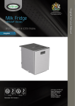
Multideck Display Cabinets
Slim 700, 900, 1200, 1500 & 1800 RF & NG Models
Pro 900, 1200, 1500 & 1800 RF & NG Models
AD2-28 Controller & RU33 Display
English
Aug 2012 Version 1
ISO 9001
Original Service Manual
By Appointment to
Her Majesty Queen Elizabeth II
Suppliers of Commercial Refrigeration
Foster Refrigerator, King’s Lynn
A Division of ITW Ltd
Foster Refrigerator,
Oldmedow Road,
King’s Lynn,
Norfolk, PE30 4JU
United Kingdom
ISO 14001
Call: +44 (0)843 216 8800 Fax: +44 (0)843 216 4700 Email: [email protected]
www.fosterrefrigerator.co.uk
1
GB
Manual Information & Health & Safety Notes
Environmental Management Policy
Disposal Requirements & Electrical Safety
Cabinet Description
Controller Display Functions & Buttons
Start Up & Operation
User Functions
AD2-28 Controller Connection Drawing & Technical Data
Service & Parameter Access & Definitions
Air & Evaporator Probe Details/Diagram
Individual Model Technical Data
Wiring Diagrams
Troubleshooting & Notes
1
2
2
3
3
3 to 4
4 to 5
5
6 to 9
9
10
11 to 12
13 to 15
The products and all information in this manual are subject to change without prior notice.
We assume by the information given that the person(s) working on these refrigeration units are
fully trained and skilled in all aspects of their workings. Also that they will use the appropriate safety
equipment and take or meet precautions where required.
The service manual does not cover information on every variation of this unit; neither does it cover the
installation or every possible operating or maintenance instruction for the units.
Make sure the power supply is turned off before making any electrical
repairs.
To minimise shock and fire hazards, please do not plug or unplug the unit
with wet hands.
During maintenance and cleaning, please unplug the unit where required.
Care must be taken when handling or working on the unit as sharp edges
may cause personal injury, we recommend the wearing of suitable PPE.
Ensure the correct moving and lifting procedures are used when relocating a
unit.
Do NOT use abrasive cleaning products, only those that are recommended.
Never scour any parts of the refrigerator. Scouring pads or chemicals may
cause damage by scratching or dulling polished surface finishes.
Failure to keep the condenser clean may cause premature failure of the
motor/compressor which will NOT be covered under warranty policy.
Please ensure the appropriate use of safety aids or Personnel Protective
Equipment (PPE) are used for you own safety.
1
GB
Product Support and Installation Contractors.
Foster Refrigerator recognises that its activities, products and services can have an adverse impact
upon the environment.
The organisation is committed to implementing systems and controls to manage, reduce and
eliminate its adverse environmental impacts wherever possible, and has formulated an
Environmental Policy outlining our core aims. A copy of the Environmental Policy is available to all
contractors and suppliers upon request.
The organisation is committed to working with suppliers and contractors where their activities have
the potential to impact upon the environment. To achieve the aims stated in the Environmental
Policy we require that all suppliers and contractors operate in compliance with the law and are
committed to best practice in environmental management.
Product Support and Installation contractors are required to:
1. Ensure that wherever possible waste is removed from the client’s site, where arrangements are in
place all waste should be returned to Foster Refrigerator’s premises. In certain circumstances waste
may be disposed of on the client’s site; if permission is given, if the client has arrangements in place
for the type of waste.
2. If arranging for the disposal of your waste, handle, store and dispose of it in such a way as to
prevent its escape into the environment, harm to human health, and to ensure the compliance with
the environmental law. Guidance is available from the Environment Agency on how to comply with
the waste management ‘duty of care’.
3. The following waste must be stored of separately from other wastes, as they are hazardous to the
environment: refrigerants, polyurethane foam, and oils.
4. When arranging for disposal of waste, ensure a waste transfer note or consignment note is
completed as appropriate. Ensure that all waste is correctly described on the waste note and include
the appropriate six-digit code from the European Waste Catalogue. Your waste contractor or Foster
can provide further information if necessary.
5. Ensure that all waste is removed by a registered waste carrier, a carrier in possession of a waste
management licence, or a carrier holding an appropriate exemption. Ensure the person receiving the
waste at its ultimate destination is in receipt of a waste management licence or valid exemption.
6. Handle and store refrigerants in such a way as to prevent their emission to atmosphere, and
ensure they are disposed of safely and in accordance with environmental law.
7. Make arrangements to ensure all staff who handle refrigerants do so at a level of competence
consistent with the City Guilds 2078 Handling Refrigerants qualification or equivalent qualification.
8. Ensure all liquid substances are securely stored to prevent leaks and spill, and are not disposed of into storm
drains, foul drain, or surface water to soil.
If not disposed of properly all refrigerators have components that can be harmful to the
environment.
All old refrigerators must be disposed of by appropriately registered and licensed waste contractors, and
in accordance with national laws and regulations.
Foster Refrigerator recommends that the equipment is electrically connected via a Residual Current
Device; such as a Residual Current Circuit Breaker (RCCB) type socket, or through a Residual Current
Circuit Breaker with Overload Protection (RCBO) supplied circuit.
2
GB
There are two ranges of Multideck – Slim & Pro. All the cabinets’ primary use is to display food
products. The Slim range has a small footprint with extra wide shelf depths so not to lose any
storage space. The Pro differs in that it can hold a larger volume of food. Each is available with
choice of a Night blind or Lockable Roller Shutter which in turn decides the side type – solid or glass
panels. The cabinets are made of 304 Stainless Steel. All cabinet lighting is supplied in the form of
LED strips.
Functions Icons
Temperature Display
Buttons/Switches
Info/Set Point Button
Increase Button/ Lights On/Off
Manual Defrost /Decrease Button
Exit/Stand-by Button
Compressor Output
Alarm
Fan Output
Defrost Output
Light Output
Instant Probe 1 Temperature
Maximum Probe 1 Temperature Recorded
Instant Probe 2 Temperature
Minimum Probe 1 Temperature Recorded
Instant Probe 3 Temperature
Keypad State Lock
Initial Set Up & Start Up
After unpacking leave to stand for 60 minutes and clean before turning on (cleaning directions are supplied
within this manual). Position the Multideck with care on a level, flat, solid surface area.
Avoid cold air from air conditioning units & direct sunlight as these factors will affect the units’ performance.
Warm air is produced from the rear of the unit & for this reason please leave a breathing area around the unit as
follows:
Gap Position
Each Side of the Unit to Wall or next Unit.
Top of Unit to Ceiling (No Rear Ventilation)*
Top of Unit to Ceiling (With Rear Ventilation)
Rear of Units Wall Spacer to Wall
Rear of Units Wall Spacer to Wall
*When positioned into a recess or similar small area.
Gap Measurement
10mm
80mm
10mm
60mm
20mm
Relevant Models
Slim & Pro
Slim & Pro
Slim & Pro
Slim
Pro
3
GB
Insert the mains plug into the wall socket and switch on. Please do not plug or unplug the unit with wet hands. The
Multideck will start automatically, displaying the actual internal temperature of the unit (area where product is
displayed). All models are pre-set at +3° C to +5°C, so no adjustments are required.
Allow the Multideck to reach its normal operating temperature before loading.
With an interruption to the main power supply, the Multideck will re-start automatically after power is restored. The
vaporiser tray (at the base of the unit) may overflow during a power cut but this is dependent on the length of time
the power is off.
Pressing this button for 3 seconds will allow the unit to be turned on or put into standby.
Access to the menu and information displayed
Press and immediately release button
With button
or
.
select the data to be displayed.
Press and button
to display the value
To exit from the menu, press button
or wait for 10 seconds.
Reset of THI, TLO, CND recordings
With button
or
select the data to be reset
Display the value with button
While keeping button
Press button
.
pressed, use button
.
for at least half a second to display the set point.
By keeping
button pressed, use button
or
to set the desired value (adjustment is
within the minimum SPL and the maximum SPH limit)
When button
Press & release
is released, the new value is stored.
then use
to select ‘LOC’. Press and hold
‘NO’. Leave for 10 seconds or briefly press
to change from ‘YES’ to
to resume
The keypad lock avoids undesired, potentially dangerous operations, which might be
attempted when the controller is operating in a public place. In the INFO menu, set
parameter LOC = YES to inhibit all functions of the buttons. To resume normal operation of
the keypad, adjust setting so that LOC = NO.
When pressed and released this button will switch on and off the display lights. This function will
work with the cabinet turned on or in standby mode.
The Multideck automatically defrosts at regular time intervals, lasting a maximum of 20 minutes
during which
will show. Defrost can be manually activated by pressing and holding
Automatic Defrost.
Defrost starts automatically as soon as the time set with parameter DFT has elapsed.
Time Defrost With DFM = TIM defrost takes place at regular intervals when the timer
reaches the value DFT. For example, with DFM = TIM and DFT = 04, defrost will take place
every 4 hours.
4
GB
Defrost type
Once defrost has started, compressor and defrost outputs are controlled according to parameter
DTY. If FID =YES, the evaporator fans are active during defrost.
Defrost termination
The actual defrost duration is influenced by a sensor T2 and defrost termination parameter DTO. So
if the sensor T2 measures the temperature DLI before the time DTO elapses, defrost will be
terminated.
Resuming Thermostatic Cycle
When defrost is over, if DRN is greater than 0, all outputs will remain off the DRN minutes, in order
for the ice to melt completely and the resulting water to drain. Also, as probe T2 is active (T2=YES),
the fans will re-start when the evaporator gets to a temperature love than FDD; or after FTO
minutes have elapsed.
Note: During a high pressure alarm, defrost is suspended. During defrost, high temperature alarm
is bypassed.
Power Supply
230Vac±10%, 50/60Hz, 3W
Relay Output
16A Resistive
Compressor
8 FLA 48 RLA
8A Resistive
Evap. Fan
2 FLA 12 RLA
Defrost
16A Resistive
Auxiliary Loads 1
7A Resistive
7A Resistive
Auxiliary Loads 2
Measurement Range
-50 / -9.9…19.9 / 80°C (NTC 10K Only)
Measurement Accuracy
<0.5°C within the measurement range
Operating Conditions
-10...+50°C; 15%...80%r.H
Controller Approvals
EN60730-1;
EN60730-2-9
EN55022 (Class B)
EN50082-1
SDFY2.SA32385
UL60730-1
Input
NTC 10KΩ@25°C
5
GB
Parameters should not be changed unless you have an understanding of their purpose and
the following instructions are fully understood.
To get access to the parameter configuration menu, press
With button
or
+
for 5 seconds
select the parameter to be modified.
Press button
and hold briefly to display the value. On releasing the button the controller
will then show the next parameter.
By keeping button
pressed, use button
or
to set the desired value. On releasing
the button the controller will store the amended value and then show the next parameter.
To exit from the setup, press button
Parameter
SCL
SPL
SPH
SP
C-H
Range
1°C
2°C
°F
-50 … SPH
SPL …120°
SPL … SPH
HYS
CRT
REF
HEA
1 … 10°
0 … 30min
CT1
0 … 30min
CT2
0 … 30min
CSD
0 … 30min
DFM
NON
TIM
FRO
DFT
0…99 Hours
DFB
YES
NO
-50.. 120°
1 … 120min
DLI
DTO
DTY
OFF
ELE
GAS
DPD
0 … 240sec
DRN
0 … 30min
DDM
RT
LT
SP
DEF
or wait for 30 seconds.
Description
Readout Scale:
Range -50/-9.9…. 19.9/80°C (With INP = SN4 Only)
Range -50 …. 120°C
Range -55 …. 240°F
Minimum limit for SP setting
Maximum limit for SP setting
Temperature set point to be achieved
Temperature Control mode:
Refrigeration
Heating
Off/On thermostat differential
Compressor rest time
Thermostat run time with faulty T1 probe.
(CT1 = 0 output with faulty T1 will always be off)
Thermostat off time with faulty T1 probe.
(CT2=0 & CT1 =>0 output with faulty T1 will always
be on)
Compressor stop delay after door has been opened
(Only if DS = YES)
Defrost Start Mode:
Defrost function is disabled
Regular time defrost
Defrost time elapses only in condition of frost
accumulation
Time interval between defrosts
Defrost timer clock
Following mains interruption, timer resumes count
Following mains interruption, timer restarts from zero
Defrost end temperature (Only if T2 = EPO)
Maximum defrost duration
Defrost Type:
Timed off cycle defrost (compressor and heater off)
Electric heater defrost (compressor off, heater on)
Hot gas defrost (compressor and heater on)
Evaporator pump down. Timed pause at start of
defrost
Drain down period
Defrost display mode:
Real (actual) air temperature
Last temperature display before start of defrost
The current set point value.
“DEF”
Default
AD2-28
All Models
Including
Starbucks
(C0A)
2 C
o
2 C
o
1
3
1
-2
5
1
REF
REF
4
2
3
1
6
6
4
2
1
1
TIM
TIM
6
4
YES
YES
20
20
10
20
OFF
ELE
0
0
2
1
DEF
SP
6
GB
DDY
0… 60 min
FID
YES
NO
FDD
-50 … 120°
FTO
0…120 min
NON
FCM
TMP
TIM
FDT
-120 … 0°
FDH
1 … 120°
FT1
0 … 180 Sec
FT2
0 … 30min
FT3
0 .. 30min
NON
ATM
ABS
REL
ALA
AHA
-50 … 120°
-50 … 120°
ALR
-12 … 0°
AHR
0 … 12°
T1
ATI
ATD
ADO
AHM
T2
T3
0… 120min
0… 30min
NON
ALR
STP
AHT
-50 … 120°
ACC
0…52 Weeks
Defrost display delay period
Time DDM is shown following defrost termination
Fans in defrost:
Fans run during defrost
Fans do not run during defrost
Evaporator fan restart temperature following defrost
(Only if T2 = EPO)
Maximum evaporator fan stop period following
defrost
Evaporator fan mode during thermostatic
control:
Fan(s) run continuously
Temperature based control. When compressor is on,
fans are on. When compressor is off, fans run as
long as temperature difference Te-Ta > FDT. Fans
on again with FDH
Time based control. When compressor is on, fans
are on. When compressor is off, fans in accordance
to parameters FT1, FT2 and FT3.
Te-Ta difference for fans to turn off after compressor
stopped. (Only if T2 = EPO and FCM = TMP)
Temperature differential for evaporator fan restart.
(Only if T2 = EPO and FCM = TMP)
Fan stop delay after compressor stop.
Timed fan stop following FT1
(With FT2 = 0 the fans remain on all the time).
Timed fan run following FT2
(With FT3 = 0 and FT2 >0 the fans remain off all the
time.
Alarm threshold configuration:
All temperature alarms are inhibited
The value set in ALA and AHA represent actual
alarm set points
The values set in ALR and AHR are alarm
differentials which relate to SP and SP + HYS
Low temperature alarm threshold
High temperature alarm threshold
Low temperature alarm differential
(With ALR = 0 the low temperature alarm is
excluded)
High temperature alarm differential
(With AHR = 0 the low temperature alarm is
excluded)
Alarm probe:
Air temperature probe used for alarm detection
Evaporator temperature probe used for alarm
detection
Third temperature probe used for alarm detection
Delay before alarm temperature warning
Delay before door open alarm warning
Operation in case of high condenser alarm (T3 =
CND)
High condenser temperature alarm inhibited
Condenser warning – ‘HC’ displayed, alarm sounds
As ‘ALR’ with compressor stopped and defrosts
suspended
Condenser alarm temperature (T3 = CND)
Condenser cleaning period.
(With ACC = 0 condenser cleaning is disabled)
10
10
YES
YES
5
5
3
2
TIM
NON
-1
-1
3
3
15
15
3
3
2
2
REL
REL
-2
8
-2
8
-5
-5
5
8
T1
T3
90
8
90
8
NON
ALR
65
65
0
0
7
GB
NON
IISM
MAN
HDD
DI2
IISL
IISH
IISP
IIHY
-50 . IISH
IISL .. 120°
IISP…IISH
1 … 10°
NON
IIFC
TMP
TIM
HDS
1…5
IIDF
0 … 99hours
SB
YES
NO
DS
DI2
YES
NO
NON
HPS
IISM
RDS
DSY
NON
LSM
button
Second parameter activated by ‘heavy’ usage
Second parameter set activated by D12 input (D12 =
IISM)
Minimum limit for IISP setting
Maximum limit for IISP setting
Temperature set point to be achieved in ‘Mode 2’
Off/On thermostat differential in ‘Mode 2’
Evaporator fan mode during ‘Mode 2’
thermostatic control:
Fans(s) run continuously
Temperature based control. When compressor is on,
fans are on. When compressor is off, fans run as
long as temperature difference Te-Ta>FDT. Fans on
again with FDH
Time based control. When compressor is on, fans
are on. When compressor is off, fans in accordance
to parameters FT1, FT2 and FT3.
Controller sensitivity for switch over between ‘Modes’
and 2. (1 = minimum, 5 = maximum)
Time interval between defrosts in ‘Mode 2’.
Standby button operation:
Standby button enabled
Standby button disabled
Door switch operation (switch made when door
closed):
Door switch enabled
Door switch disabled
Configuration digital input operation:
Digital input 2 not activated
High pressure alarm when contact opens
‘Mode 2’ parameters active when contact closes
Defrost initiated when contact closes
Defrost Synchronisation
Light control mode:
Light input is excluded
Light output operation is activated/deactivated by
MAN
DOR
OA1
Switchover method to second parameter set:
Second parameter set is excluded
Second parameter set is activated/ deactivated by
NON
0-1
LGT
2CU
2EU
AL0
AL1
button
(With OA1 = LGT)
Light output is switched on when door is opened
(With OA1 = LGT and DS = YES)
Auxiliary relay operation:
Output disabled (always off)
Contacts open/close with standby/on mode
Output enabled for light control
Control of electric defrost of an auxiliary compressor
Control of an electric defrost of second evaporator
Contacts open when an alarm condition occurs
Contacts close when an alarm condition occurs
(Relay contacts open when in standby mode)
HDD
NON
1
1
1
4
1
1
1
4
NON
NON
3
3
6
6
YES
YES
YES
NO
NON
HPS
NON
MAN
0-1
LGT
8
GB
OA2
NON
0-1
LGT
2CU
2EU
AL0
AL1
2CD
0 … 120sec
INP
SN4
ST1
-12.5...12.5°C
OS1
T2
OS2
YES
NO
-12.5…12.5°C
OS3
NON
DSP
CND
2EU
-12.5…12.5°C
TLD
1 … 30min
SIM
ADR
0 … 100
1… 255
T3
Auxiliary relay operation:
Output disabled (always off)
Contacts open/close with standby/on mode
Output enabled for light control
Control of electric defrost of an auxiliary compressor
Control of an electric defrost of second evaporator
Contacts open when an alarm condition occurs
Contacts close when an alarm condition occurs
(Relay contacts open when in standby mode)
AUXHILLARY Compressor Start Delay
Temperature sensor(s) type:
10k NTC type thermistor (red writing)
1k PTC type thermistor (Black Writing)
Air temperature probe (T1) offset.
T2 Probe enabling:
T2 Probe enabled
T2 probe disabled
T2 probe temperature offset
T3 Probe function:
T3 probe disabled
T3 temperature displayed
Condenser temperature measurement
Second evaporator temperature measurement
T3 probe temperature offset
Delay for min (TLO) and max. (THI) temperature
logging
Display Slowdown
AD2-28 address for PC communication
0-1
AL0
0
0
SN4
SN4
0
0
NON
YES
0
0
NON
DSP
0
0
10
10
5
1
5
1
*Yellow denotes change from default controller setting
9
R404a
R404a
R404a
R404a
R404a
R404a
R404a
FMPRO900NG
FMPRO1200RF
FMPRO1200NG
FMPRO1500RF
FMPRO1500NG
FMPRO1800RF
FMPRO1800NG
550 grams
R404a
R404a
R404a
R404a
R404a
R404a
R404a
R404a
R404a
FMSLIM700RF
FMSLIM900NG
FMSLIM900RF
FMSLIM1200NG
FMSLIM1200RF
FMSLIM1500NG
FMSLIM1500RF
FMSLIM1800NG
FMSLIM1800RF
750 grams (per system)
750 grams (per system)
1200 grams
1200 grams
1050 grams
1050 grams
760 grams
760 grams
550 grams
750 grams (per system)
750 grams (per system)
1200 grams
1200 grams
1050 grams
1050 grams
760 grams
760 grams
Gas Charge
R404a
FMSLIM700NG
Slim
R404a
Gas
FMPRO900RF
Pro
Model
Embraco NT6222GK (x2)
Embraco NT6222GK (x2)
Embraco NT6226GK
Embraco NT6226GK
Embraco NT6226GK
Embraco NT6226GK
Embraco NT6222GK
Embraco NT6222GK
Embraco NT6222GK
Embraco NT6222GK
Embraco NT6222GK (x2)
Embraco NT6222GK (x2)
Embraco NT6226GK
Embraco NT6226GK
Embraco NT6226GK
Embraco NT6226GK
Embraco NT6222GK
Embraco NT6222GK
Compressor
3.0m x 0.064” (x2)
3.0m x 0.064” (x2)
3.5m x 0.064”
3.5m x 0.064”
3.5m x 0.064”
3.5m x 0.064”
4.0m x 0.064”
4.0m x 0.064”
4.0m x 0.064”
4.0m x 0.064”
3.0m x 0.064” (x2)
3.0m x 0.064” (x2)
3.0m x 0.064”
3.0m x 0.064”
3.5m x 0.064”
3.5m x 0.064”
4.0m x 0.064”
4.0m x 0.064”
Capillary
230/50/1
230/50/1
230/50/1
230/50/1
230/50/1
230/50/1
230/50/1
Electric
Electric
Electric
Electric
Electric
Electric
Electric
230/50/1
Electric
230/50/1
230/50/1
Electric
230/50/1
230/50/1
Electric
Electric
230/50/1
Electric
230/50/1
230/50/1
Electric
Electric
230/50/1
Electric
Electric
230/50/1
230/50/1
Voltage
Electric
Electric
Defrost
Type
65.6
65.6
52.4
52.4
44.8
44.8
38.4
38.4
34.3
34.3
65.6
65.6
52.4
52.4
44.8
44.8
38.4
38.4
Power
Consumption
kW/48hrs
13
13
10
10
10
10
10
10
10
10
13
13
10
10
10
10
10
10
Fuse
Rating
(Amps)
10
Note: The Power Consumption values referred to as tested are to the ECA test standard. Actual power consumption will be greatly affected by ambient
temperature, loading, usage and cabinet maintenance.
For 1800 model cabinets only where 2 compressors are fitted there is a 20 second delay between compressor starts so the start current of 20A is not exceeded.
The suction pressure as per climate class 3 (see below) is between -8 and -10 ºC approximately 3.5 bar, with a discharge temperature of +40 ºC (clean
condenser) approximately 17.3 bar.
The cases are designed to work in an ambient temperature not exceeding 25 degrees centigrade (C) with a relative humidity not exceeding 60% (RH) Climate
Class 3. The frontal airflow should be < 0,2m/s
GB
GB
11
GB
12
GB
Problem
Audible & Visual
Alarms/Warnings
Possible Cause
> Unit Low Temperature Alarm
> Unit High Temperature Alarm
>
Probe T1 failure (Air)
>
Probe T2 failure (Evaporator)
>
Probe T3 failure (Product)
> High Pressure Alarm (The main lights
will also go off)
> Defrost In Progress
Compressor will not start
> No voltage in socket
> Electrical conductor or wires may
be cut
> Defective electrical component:
thermostat, relay, thermal
protector etc.
> Compressor motor has a winding
open or shorted
> Compressor stuck/seized
> Temperature control contacts are
open
> Incorrect wiring
> Fuse blown or circuit breaker
tripped.
> Power cord unplugged
> Controller temperature set too
high
> Cabinet in defrost cycle
The temperature is too cold
> Controller is set to a lower than
recommended temperature
setting
> Controller does not disconnect
the condensing unit
> Control contacts are stuck closed
> Defective or incorrect
temperature control
Solution
> Cancel audible alarm and
investigate cause.
> Cancel audible alarm and
investigate cause.
> Check and replace the air
probe
> Check and replace the
evaporator probe
> Check and replace the product
probe.
> Check ambient temperature
and refrigeration system.
> Wait for defrost cycle to finish
> Use voltmeter to check
> Use ohmmeter to check for
continuity
> Replace defective component
> Measure ohmic resistance of
main and auxiliary winding
using ohmmeter. Compare
with correct values
> Change compressor
> Repair or replace the contacts
> Check wiring diagram and
correct
> Replace fuse or reset circuit
breaker
> Plug in power cord.
> Set controller to lower
temperature.
> Wait for defrost cycle to finish
> Adjust to a higher
temperature setting and check
if the compressor stops
according to controllers
operating range.
> Check the insulation of the
thermostat. If problem
persists, change the
thermostat
> Change the control. Check
amperage load
> Determine correct control and
replace.
13
GB
The temperature is not cold
enough
> Controller is set to a higher
temperature than recommended
> Condenser is dirty
> Adjust to lower temperature
setting
> Clean condenser
> The refrigerator has been placed
at an inadequate location
> The unit must not be near
stoves, air conditioning units,
walls that are exposed to the
sun, or places that lack
sufficient air flow.
> If there is air in the system,
purge and recharge
> Compressor is inefficient or there
is a high pressure due to the air
in the system
> Iced up evaporator coil
> Restriction in system
> Excessive heat load placed in
cabinet
> The refrigerator has been
overcharged with the refrigerant
gas
> The refrigerant gas is leaking
> The evaporator and/or condenser
fans are not working
> Blocking air flow
> Check temperature control,
refrigerant charge, and defrost
mechanism. Remove all ice
manually and start over.
> Locate exact point of
restriction and correct
> Advise user not to put in
products that are hot.
> Check to see if condensation
or ice crystals have formed on
the suction line. If so, charge
with the correct amount of
gas.
> Find the location of gas leak in
order to seal and replace the
defective component. Change
the drier. Perform a good
vacuum and recharge unit.
> Check electrical connections
and make sure that the fan
blade isn’t stuck. Replace the
fan motor if it doesn’t work.
> Re-arrange product to allow
for proper air flow.
> Fuse blown or circuit breaker
tripped
> Replace fuse or reset circuit
breaker.
Electrical Shocks
> Wires or electrical components
are in direct contact with metallic
parts.
> Check for appropriate
insulation on the connections
of each component.
Noise
> The refrigerator is not properly
levelled
> Check if the noise goes away
after you level the refrigerator
> The condenser is not fastened
correctly. Copper tubing is in
contact with other metal parts
> While the compressor is
working, check to see if metal
parts are in contact with one
another and/or if the screws
that fasten the condenser are
tightened.
14
GB
> The evaporator and/or condenser
fans are loose
> Compressor has an internal noise
> Loose part(s)
Condensing unit runs
for long periods of time
> Excessive amount of warm
product placed in cabinet
> Dirty condenser coil
> Evaporator coil iced over
> Check if the fans are securely
fastened. Also, check if the fan
blades are loose, broken or
crooked. If so, change the
faulty blade.
> If the noise persists after all
other measures have been
taken, it may be originating
from the compressor.
> Locate and tighten loose
part(s)
> Advise user that this unit is
not meant for cooling hot
products and should only be
used to maintain already
cooled produce
> Clean condenser coil
> Unplug unit and allow coil to
defrost. Make sure thermostat
is not set too cold. Ensure that
door gasket(s) are sealing
properly. Select manual
defrost and ensure system
works.
15
GB
> Page Left Blank Intentionally <
16
GB
Foster European Operations
France
Foster Refrigerator France SA
Tel: (33) 01 34 30 22 22. Fax: (33) 01 30 37 68 74.
Email: [email protected]
Germany
Foster Refrigerator Gmbh,
Tel: (49) 781 990 7840. Fax (49) 781 990 7844.
Email: [email protected]
Foster Refrigerator
Oldmedow Road
Kings Lynn
Norfolk
PE30 4JU
Tel: 0843 216 8833
Fax: 0843 216 4707
Website: www.fosterrefrigerator.co.uk
Email: [email protected]
a Division of ‘ITW (UK) Ltd’
MULTIDECK AD2-28/SM 08/12 GB
17