1
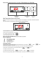
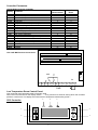
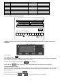
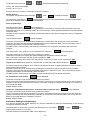
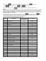
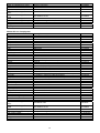
Packaged Coldroom
0
Contents
Environmental Management Policy
Disposal Requirements
Introduction
Control Panel
LCD 28 Controller With LCD 16 Display used on All Rooms From E5167380 From Feb 06
High Temperature Room LDU 15 Controller
Low Temperature Room CDC 122 Controller From Dec 04 to Feb 05
Low Temperature Room LCD 15 Controller From Feb 05
Parts Lists
Water Cooler System Filling Instruction
Page
1
1
2
2
2 to 5
6 to 7
7 to 9
9 to 12
12 to 14
15
Environmental Management Policy for Service Manuals and Duets.
Product Support and Installation Contractors
Foster Refrigerator recognises that its activities, products and services can have an adverse impact upon the
environment.
The organisation is committed to implementing systems and controls to manage, reduce and eliminate its adverse
environmental impacts wherever possible, and has formulated an Environmental Policy outlining our core aims. A
copy of the Environmental Policy is available to all contractors and suppliers upon request.
The organisation is committed to working with suppliers and contractors where their activities have the potential to
impact upon the environment. To achieve the aims stated in the Environmental Policy we require that all suppliers
and contractors operate in compliance with the law and are committed to best practice in environmental
management.
Product Support and Installation contractors are required to:
1. Ensure that wherever possible waste is removed from the client’s site, where arrangements are in place all
waste should be returned to Foster Refrigerator’s premises. In certain circumstances waste may be disposed
of on the clients site; if permission is given, if the client has arrangements in place for the type of waste.
2. If arranging for the disposal of your waste, handle, store and dispose of it in such a way as to prevent its
escape into the environment, harm to human health, and to ensure the compliance with the environmental law.
Guidance is available from the Environment Agency on how to comply with the waste management ‘duty of
care’.
3. The following waste must be stored of separately from other wastes, as they are hazardous to the environment:
refrigerants, polyurethane foam, oils.
4. When arranging for disposal of waste, ensure a waste transfer note or consignment note is completed as
appropriate. Ensure that all waste is correctly described on the waste note and include the appropriate six-digit
code from the European Waste Catalogue. Your waste contractor or Foster can provide further information if
necessary.
5.
Ensure that all waste is removed by a registered waste carrier, a carrier in possession of a waste management
licence, or a carrier holding an appropriate exemption. Ensure the person receiving the waste at its ultimate
destination is in receipt of a waste management licence or valid exemption.
6. Handle and store refrigerants in such a way as to prevent their emission to atmosphere, and ensure they are
disposed of safely and in accordance with environmental law.
7. Make arrangements to ensure all staff who handle refrigerants do so at a level of competence consistent with
the City Guilds 2078 Handling Refrigerants qualification or equivalent qualification.
8.
Ensure all liquid substances are securely stored to prevent leaks and spill, and are not disposed of to storm
drains, foul drain, surface water to soil.
DISPOSAL REQUIREMENTS
If not disposed of properly all refrigerators have components that can be harmful to the environment. All old
refrigerators must be disposed of by appropriately registered and licensed waste contractors, and in accordance
with national laws and regulations.
1
Introduction
Constructed on site from foamed insulated panels provided with profiled edges and heavy duty Fosterloks for
positive locking and long-term stability.
The condensing system is incorporated in the front coldroom panel locked into position.
The temperature controller, On/Off switch and light switch are located in the hinged front panel.
Access to the condensing system is by removal of the retaining screws from the right hand side of the hinged
panel.
Control Panel used on High and Low temperature coldrooms from E5167380 Feb 2006
Temperature
Controller
Mains ON/OFF
Switch
Interior Light
Switch
Controller Operation
LCD 28CS4E-B (00-555739) Controller
Operation Guidelines
LCD 16 Display (00-555740)
Initial Start Up.
Start Up & self Test:
The indication is only displayed during the first three seconds following the mains electrical power being applied to
the unit. During this period the controller performs a self-check.
Once the self-check has been completed
Press and hold
OFF
will be displayed.
for three seconds. The unit will start and the air temperature will be displayed.
Check temperature set point.
Important to note that the ability to increase and decrease the set point is not a function available to the user on the
freezer rooms as the set point is fixed, but limited adjustment is available on the High temperature rooms.
To make adjustments to the set point it is necessary to access the parameter and alter SPL and SPH accordingly.
Check set point by pressing the button
To increase set point press
To decrease set point press
+
+
until required temperature is displayed.
until required temperature is displayed.
Factory Temperature Set Point
Refrigerator +1°C to +4°C. Freezer -18°C to -21°C. Exit from set up occurs after 10 seconds if no button is pressed.
2
Manual Defrost.
To initiate a manual defrost press and hold
dEF
will be displayed release.
REC
On completion of the defrost
will be displayed until the cabinet temperature is achieved and then it will
revert to displaying the normal cabinet temperature.
Set Unit to Standby.
Press
display shows
OFF
Standby Indication
This indication is displayed while the unit is not operating but with mains power applied to the unit. This mode may
be used for internal cleaning regimes and short periods when the unit is not required.
For extended periods of inactivity the mains supply should be isolated.
Alarm and Warnings
High temperature alarm
HI
Will be displayed.
The alarm will sound but can be silenced by pressing any of the buttons, however it will return after the pre-set
designated period. The unit returning to normal operating temperature will automatically cancel the alarm.
Possible Causes: Evaporator fan not working. Restricted airflow through airduct. Evaporator iced up. Compressor
not working.
Low temperature alarm.
LO
Will be displayed.
The alarm will sound but can be silenced by pressing any of the buttons and the unit will continue to operate,
however it will return after the pre-set designated period. The unit returning to normal operating temperature will
automatically cancel the alarm.
Possible Causes: Controller faulty (not switching compressor off). Compressor secondary relay will not de-energise
(low temperature models).
Door Open Alarm. (Only applies to cabinets fitted with door switches.)
DO
Will be displayed.
The alarm will sound but can be silenced by pressing.
The display will continue to display the alarm message until cancelled by shutting the door.
Possible Causes: Faulty door switch. Door left open for more than 5minutes.
High Pressure Alarm (Only applies to machines fitted with a condenser probe).
HP
Will be displayed
This alarm relate to the condenser which must be checked and cleaned at regular intervals the frequency being
determined by site conditions.
The alarm will sound but can be silenced by pressing any of the buttons and the unit will continue to operate,
however it will return after the pre-set designated period. The unit returning to normal operating temperature will
automatically cancel the alarm.
Possible Causes: Condenser fan not working. Condenser blocked/ dirty. Condenser obstructed.
Air Temperature Probe Failure.
E1
Will be displayed.
The alarm will sound but can be silenced by pressing any button.
There is no further action that can be taken by the user in this instance. During this period the unit will continue to
operate but have a reduced performance.
Action: Replace Probe.
Evaporator Temperature Probe Failure. (Automatic Defrost Cabinets Only)
E2
Will be displayed.
The alarm will sound but can be silenced by pressing any button.
There is no further action that can be taken by the user in this instance. During this period the unit will continue to
operate satisfactorily, but this failure will have an effect on the defrost and therefore efficiency if allowed to
continue.
Action: Replace Probe.
3
Information Menu
Pressing and releasing
activates the information menu. From this menu you can display the
temperature relating to T1 (air probe), T2 (evaporator probe, if fitted) and T3 (condenser probe, if fitted).
The maximum temperature (THI) and the minimum temperature (TLO) the cabinet has achieved since it was last
re-set.
The total operating time of the condenser (CND), since it was last cleaned, and the keyboard status (LOC).
The information to be displayed can be selected sequentially by pressing
through the menu using the
Once selected press
or
repeatedly or scrolling
buttons.
to display the value
Exit from the info menu by pressing
or is automatic after 6 seconds if no buttons are pressed.
To reset the temperature settings recorded in THI and TLO and the hours counted in CND, access the info
menu press
to display the value plus
simultaneously for resetting to be completed.
To check the LOC status scroll through to LOC, press
to display status – YES to lock keys. – NO to
leave keys accessible.
NOTE: with the keys locked it is not possible to turn the unit off or ON or to check the set point
Parameter Setting and Adjustment
It is strongly advised that before adjusting any Service Parameters a thorough understanding of the following
instructions should be obtained.
The parameters are accessed by pressing the following keys in succession
keeping them pressed for 5 seconds.
+ “set” +
and
After this period the first parameter ‘SCL’ will be displayed.
Press button
Press
to pass from one parameter to the next and button
to display the value +
Exit from set up is by pressing
or
to go back.
to change it.
or is automatic if no buttons are pressed for 30 seconds
NOTE:
When receiving a replacement controller the unit will be set with the default settings. Change the settings to those
relating to the particular model. After changing parameter ‘SCL’ from ‘1’ to ‘2’ moving through parameters ‘SPL’,
‘SP’, ‘FDD’, IISL’ and ‘IISP’ you may find that ‘-or’ will be displayed. ‘-or’ indicates that the control setting is out of
range.
To get the parameter back into range, for example ‘SPL’, press
to display the value +
continue pressing both buttons until the display shows the temperature required then release both buttons.
Use the same procedure to adjust all of the parameters displaying ‘-or’.
LCD 28CS4E-B (00-555735) Controller Parameter lists
Mnem.
ScL
SPL
SPh
SP
hYS
crt
cdc
cSd
dFr
dLi
Definition
Readout scale
Minimum setpoint [ I ]
Maximum setpoint [ I ]
Setpoint [ I ]
Thermostat hysteresis [ I ]
Minimum compressor rest time
10 min. run cycle with PF1
Compressor Stop delay after door open
Defrost frequency [ I ]
Defrost end temperature
Min.
Max
1°C; 2°C; °F
-30
SPH
SPL
30
SPL
SPH
0.1
10
0
30
0
10
0
30
0
24
-30
30
4
Default
1°C
-25
10
-20
2.5
1
6
1
3
15
Dim.
flag
°C
°C
°C
°K
min.
min.
min.
1/24h
°C
FPC HT
2
1
3
1
3
2
7
1
4
20
FPC LT
2
-21
-21
-21
3
2
7
1
4
50
dto
dty
drn
ddY
Fid
Fdd
Ftc
Atl
Ath
Atd
Ado
Aht
Ahm
Acc
hdS
iiSM
iiSL
iiSH
iiSP
iiHY
iidF
iiFt
Sb
dS
oAu
oS1
t2
OS2
T3
oS3
tLd
Sim
Adr
Maximum defrost duration
Defrost type
Drain down time
Display control during defrost
Fan operation in defrost
Evaporator. Fan re-start
Fan timed control [ I ]
Low temperature alarm
High temperature alarm
Temperature alarm delay
Door alarm delay
Condenser HP Alarm
AHT alarm management
Condenser cleaning
Eco->Heavy Duty sensitivity
2nd parameter set management
Minimum setpoint [ II ]
Maximum setpoint [ II ]
Setpoint [ II ]
Thermostat hysteresis [ II ]
Defrost frequency [ II ]
Fan timed control [ II ]
Stand By button function
Door switch enabling
AUX Output Control
Air probe offset
Evaporator. Probe enabling
Evaporator. Probe offset
Condenser. Probe enabling
Condenser. Probe offset
Logging Temp. Delay
Display slowdown
Unit address
1
120
FAN; ELE; GAS
0
30
0
60
NO
YES
-30
30
NO
YES
-12
0
0
12
0
120
0
30
0
70
NON; ALR; STP
0
52
1
5
NON; MAN; HDD
-30
IISH
IISL
30
IISL
IISH
0.1
10
0
24
NO
YES
NO
YES
NO
YES
NON; 0-1; ALR
-12.5
12.5
NO
YES
-12.5
12.5
NO
YES
-12.5
12.5
1
30
0
100
1
255
20
ELE
3
10
NO
-50
YES
0
5
30
5
60
NON
0
3
NON
-25
10
-20
3
1
NO
YES
NO
ALR
0
YES
0
NO
0
5
3
1
LCD 28CS4E-B (00-555735) Controller Electrical Connections
5
min.
flag
min.
min.
flag
°C
flag
°K
°K
min.
min.
°C
flag
wks
flag
flag
°C
°C
°C
°K
1/24h
flag
flag
flag
flag
°K
flag
°K
flag
°K
min.
exp.
exp.
20
OFF
2
10
YES
5
NO
-5
5
90
5
60
NON
0
3
NON
-25
10
-20
3
1
NO
NO
NO
NON
0
NO
0
NO
0
5
3
1
20
ELE
2
20
NO
5
NO
-5
5
90
5
60
NON
0
3
NON
-25
10
-20
3
1
NO
NO
NO
NON
0
YES
0
NO
0
5
3
1
Detail shows high temperature controller FPC2H Models up to E5167380
lae
aux
aux
set
Temperature
Controller
Mains ON/OFF
Switch
Interior Light
Switch
High Temperature Room Control Panel.
When the controller is switched on a single line appears on the display for 3 seconds to indicate the autotest
period.
After this period the air temperature measured by the T1 probe is displayed.
LDU 15 Controller
lae
aux
aux
set
Check temperature set point.
Check set point by pressing the “set” button
To increase set point press “set” +
To decrease set point press “set” +
Factory Temperature Set Point +1°C.
Exit from set up occurs after 10 seconds if no button is pressed.
Alarms and Warnings
HI
LO
E1
DF
CLN
High Temperature Alarm
Low Temperature Alarm
T1 Probe Failure
Defrosting in Progress
Clean Condenser
Controller Set Up.
The parameters are accessed by pressing the following keys in succession
+ “set” +
keeping them pressed for 3 seconds.
Access to the parameters has been achieved with the first parameter SCL being displayed.
To pass from one parameter to the next press either the
or
key
To display the value press. “set”
To change the value press “set” +
to increase, or “set” +
to decrease.
Exit from set up by pressing “aux” or is automatic after 30 seconds if no buttons are pressed.
6
and
Controller Parameters
LDU151E-BG Controller 00-555357
Display
SCL
SPL
SPH
SP
HYS
CRT
CDC
DFR
DTO
DDY
ATL
ATH
ATD
ACC
OAU
BAU
OS1
SIM
ADR
LDU151E-B
Default Values
1°C
00
08
03
3
1
7
4
20
1
-3
5
60
00
NON
NON
00
00
01
Parameter
Readout Scale
Minimum Temperature Set Point
Maximum Temperature Set Point
Effective Temperature Set Point
Hysteresis
Compressor Rest Time (minutes)
Compressor Regulation with T1 Fail
Defrosting Frequency (/24 hours)
Defrosting Duration (minutes)
Defrost Display Control
Low Alarm Differential
High Alarm Differential
Temperature Alarm Delay (minutes)
Condenser Clean Interval
Auxiliary Output Mode of Operation
Auxiliary Button Mode of Operation
T1 Offset
Display Slowdown
Address
LDU 151E-BG Electrical Connections
Mod.
LDU 151E-HOL
T1
-25.0 + 25.0
High Temp
Room
1°C
00
08
02
3
1
7
4
20
1
-3
10
90
00
NON
NON
00
00
01
DATE
NTC
16(4)A
PWR
230V~
± 10 %
50/60 Hz 3W
DATA
AUX
T1
1
2
3
4
5
6
7
8
9
10
11
PWR
Low Temperature Room Control Panel.
CDC Controller from December 2004 to February 2005
When the unit is switched on the display shows “- - -“ for a period of five seconds, during which the controller
performs a self-check. The display then shows the air temperature measured by probe 1.
5
CDC Controller
6
7
1
3
2
4
CDC 122
7
Check Set Point – Low point of temperature band.
Press and hold button 1 (
)
Increase Set Point
Press and hold button 1 (
). Press button 3 (
)
until required temperature is displayed.
Decrease Set Point.
Press button. 1
(
). Press button 4 (
) until required temperature is displayed.
Manual Defrost
Press and hold button 2 (
). Press button 4 (
) a timed defrost will follow.
Indicators
LED 5 Compressor on (
). LED 6 Evaporator Fan on (
). LED 7 Defrost on (
)
Alarms and Warnings
PF1 indicates air probe failure.
PF2 indicates evaporator probe failure.
Access to the control parameters is achieved by pressing sequences: -
(
)
(
+
)
+
(
) and holding in the keys for a period of 4 seconds.
(
It is possible to scroll through the parameters by pressing: The value of a selected parameter is checked by pressing:-(
time, (
)
+(
)
or
(
)
or
(
)
) and may be altered by pressing, at the same
)
Exit from set up occurs after 10 seconds if no key is pressed
If an alarm condition is entered the alarm buzzer will sound and ‘ALM’ will flash on the display. The alarm may be
acknowledged by pressing any key causing the buzzer to cease and the display will alternate between ‘ALM’ and
air temperature while the alarm condition persists. The alarm will re-sound every 30 minutes while an alarm
condition persists.
LAE CDC 122-T1-R2BS PARAMETER SETTINGS (15246156).
Display:
SPL
SPH
HYS
COF
CON
CDC
CRS
DRE
DLI
DTO
DRP
DIS
DTY
DOP
FCT
FRS
FID
Parameter:
CDC122T1R2B
(Default Values)
Low Temp Rooms
-30
20
02
00
00
05
00
06
10
30
03
5
ELE
CON
01
-10
00
-25
-15
3
0
0
7
0
6
50
20
3
20
ELE
CON
-01
5
00
Minimum temperature setpoint
Maximum temperature setpoint
Hysteresis
Refrigeration minimum off time
Refrigeration minimum on time
Compressor duty cycle
Compressor restart delay
Defrost repetition time
Defrost limit temperature
Defrost time out
Dripping time
Display in defrost
Defrost type
Defrost optimisation
Evaporator fan control
Fan restart after defrost
Fan operation during defrost
8
ALO
AHI
ADL
AIN
OS1
OS2
OS3
SIM
ADR
Low alarm threshold
High alarm threshold
Temperature alarm delay
Alarm input selection
Air probe offset
Evaporator probe offset
Display probe offset
Thermal mass simulation
Address / peripheral number
-32
22
10
01
00
00
00
00
01
-25
-12
90
01
00
00
00
00
01
CDC 122 T1R2 B Electrical Connections
Mod.
CDC 122 T1R2 B
Date
5 (1) A 240V ac
5(3) A 240V ac
5 (1) A 240V ac
PWR
12V~
± 10%
3W
PTC
T2
T
1
2
3
4
5
6
7
8
9
1
11
12
PWR
Operation Guidelines for Foster controller part number 00-555462 low temperature models FPC2L up to
E5165449.
LCD 15 Controller
Initial Start Up.
Start Up & self Test:
The indication is only displayed during the first three seconds following the mains electrical power being applied to
the unit. During this period the controller performs a self-check.
Once the self-check has been completed
Press and hold
OFF
will be displayed.
for three seconds. The unit will start and the air temperature will be displayed.
Check temperature set point.
Important to note that the ability to increase and decrease the set point is not a function available to the user as the
set point is fixed. To make adjustments to the set point it is necessary to access the parameter and alter SPL and
SPH accordingly.
Check set point by pressing the button
To increase set point press
+
until required temperature is displayed.
9
To decrease set point press
+
until required temperature is displayed.
Factory Set Temperature Range
Freezer -18°C to -21°C.
Exit from set up occurs after 10 seconds if no button is pressed.
Manual Defrost.
To initiate a manual defrost press and hold
when
dEF
is displayed release.
rEc
On completion of the defrost
will be displayed until the cabinet temperature is achieved after which it
will revert to displaying the normal cabinet temperature.
Alarm and Warnings
HI
High temperature alarm.
Will be displayed.
The alarm will sound but can be silenced by pressing any of the buttons, however it will return after the pre-set
designated period as set in parameter ‘ATH’. The unit returning to normal operating temperature will automatically
cancel the alarm.
Possible Causes: Evaporator fan not working. Restricted airflow through airduct. Evaporator iced up. Compressor
not working.
Low temperature alarm.
LO
Will be displayed.
The alarm will sound but can be silenced by pressing any of the buttons and the unit will continue to operate,
however it will return after the pre-set designated period as set in parameter ‘ATH’. The unit returning to normal
operating temperature will automatically cancel the alarm.
Possible Causes: Controller faulty (not switching compressor off). Compressor secondary relay will not deenergise.
Door Open Alarm. (Only applies to rooms fitted with door switches.)
DO
Will be displayed.
The alarm will sound but can be silenced by pressing any button.
The display will continue to display the alarm message until cancelled by shutting the door.
After 1 minute the compressor will stop, as set in parameter ‘CSD’.
Possible Causes: Faulty door switch. Door left open for more than 5 minutes, as set in parameter ‘ADO’.
High Pressure Alarm (Only applies to units fitted with a condenser probe). Will be displayed
HP
This alarm relate to the condenser which must be checked and cleaned at regular intervals the frequency being
determined by site conditions.
The alarm will sound but can be silenced by pressing any of the buttons and the unit will continue to operate,
however it will return after the pre-set designated period as set in parameter ‘ATH’. The unit returning to normal
operating temperature will automatically cancel the alarm.
Possible Causes: Condenser fan not working. Condenser blocked/ dirty. Condenser obstructed.
Air Temperature Probe Failure.
E1
Will be displayed.
The alarm will sound but can be silenced by pressing any button.
There is no further action that can be taken by the user in this instance. During this period the unit will continue to
operate but have a reduced performance with the compressor running for 7 minutes and resting for 3 minutes as
set in parameter ‘CDC’.
Action: Replace Probe.
Evaporator Temperature Probe Failure. (Automatic Defrost Cabinets Only)
E2
Will be displayed.
The alarm will sound but can be silenced by pressing any button.
There is no further action that can be taken by the user in this instance. During this period the unit will continue to
operate satisfactorily with the defrost being controlled on a timed basis and not temperature which may have an
effect on the overall efficiency if allowed to continue.
Action: Replace Probe.
Parameter Setting and Adjustment
It is strongly advised that before adjusting any Service Parameters a thorough understanding of the following
instructions should be obtained.
The parameters are accessed by pressing the following keys in succession
keeping them pressed for 5 seconds.
After this period the first parameter ‘SCL’ will be displayed.
10
+ “set” +
and
Press button
Press
to pass from one parameter to the next and button
to display the value +
Exit from set up is by pressing
or
to go back.
to change it.
or is automatic if no buttons are pressed for 30 seconds
NOTE:
When receiving a replacement controller the unit will be set with the default settings. Change the settings
to those relating to the particular model. After changing parameter ‘SCL’ from ‘1’ to ‘2’ moving through
parameters ‘SPL’, ‘SP’, ‘FDD’, IISL’ and ‘IISP’ you may find that ‘-or’ will be displayed. ‘-or’ indicates that
the control setting is out of range.
To get the parameter back into range, for example ‘SPL’, press
to display the value +
and
continue pressing both buttons until the display shows the temperature required then release both buttons.
Use the same procedure to adjust all of the parameters displaying ‘-or’.
Foster Controller part number 00-555462 Parameter list
Display:
Parameter:
LCD 15C S3E
FPC (Lt Rooms)
(Default Values)
SCL
Readout scale
1°C
2°C
SPL
Minimum setpoint [ I ]
-25
-25
SPH
Maximum setpoint [ I ]
10
-15
Setpoint [ I ]
-20
-21
SP
HYS
Thermostat hysteresis [ I ]
3
3
CRT
Minimum compressor rest time
2
1
CDC
10 min. run cycle with PF1
5
7
CSD
Cmpr.Stop delay after door open
1
1
DFR
Defrost frequency [ I ]
4
4
DLI
Defrost end temperature
15
50
DTO
Maximum defrost duration
20
15
DTY
Defrost type
ELE
ELE
DRN
Drain down time
3
3
DDY
Display control during defrost
5
20
FID
Fan operation in defrost
NO
NO
FDD
Evapor. Fan re-start
-10
5
FTC
Fan timed control [ I ]
YES
NO
ATL
Low temperature alarm
-5
-5
ATH
High temperature alarm
5
5
ATD
Temperature alarm delay
30
90
ADO
Door alarm delay
5
0
AHT
Condenser HP Alarm
60
60
AHM
AHT alarm management
ALR
NON
ACC
Condenser cleaning
20
0
HDS
Eco->Heavy Duty sensitivity
3
3
IISM
2nd parameter set management
NON
NON
IISL
Minimum setpoint [ II ]
-25
-25
IISH
Maximum setpoint [ II ]
10
10
IISP
Setpoint [ II ]
-20
-20
IIHY
Thermostat hysteresis [ II ]
3
3
11
IIDF
Defrost frequency [ II ]
4
4
IIFT
Fan timed control [ II ]
YES
YES
SBY
Stand By button function
YES
NO
Door switch enabling
NO
NO
0
0
YES
YES
0
0
NO
NO
DS
OS1
T2
OS2
T3
Air probe offset
Evapor. Probe enabling
Evapor. Probe offset
Condens. Probe enabling
OS3
Condens. Probe offset
0
0
TLD
Logging Temp. Delay
5
5
SIM
Display slowdown
3
3
ADR
Unit address
1
1
LCD151CSE Electrical Connections
Mod.
LCD15CS3E
T1, T2, T3
-40.0 +80.0 °C
PWR
L-N 230V~
Date
(cod. SN2…)
±10% 50/60 Hz
T3
7 (2)A
T2
1
DATA
3W
17
16
T1
15
14
13
7 (2)A 7 (2)A
15A
1
2
3
L
4
5
N
Parts Lists
PC2H-ZF High Temp System
Item
Compressor
Compressor
Condenser Coil
Condenser Fan
Evaporator Fan Guard
Evaporator Coil
Evaporator Fan
Drier
HP Pressure Switch
Vap Tray Heater Rod
Vap Tray Temperature Switch
Accumulator
Controller
Display
Air Probe
Controller
Air Probe
ON / Off Rocker Switch
Light Switch
Bulkhead Light
Light Bulb
Description
CAJ9510Z 230/50/1
MX18TB R404 HBP
Ring Mount 25W C/W Blade
White
Ring Mount 25w C/W Blade
DML 033S
28 BAR
PA389-2 250W 240V
Cut Out 70°c Cut In 55°c
3/8 Inlet 1/2 Outlet
LCD28CS4E-B (From Feb 2006)
LCD 16
SN2K250T1 For LCD 28 Controller
LDU151E-BG c/w NTC2K Probe (Up to Feb 2006)
NTC 2K
ARCO C1550+EN60
C1353AT+EN60 2W
Loblite 7000.00 White
60W BC Pearl 240V R/S
12
Part Number
15422115
00-555675
00-555561
00-555569
01-252381-01
00-555565
00-555568
00-555388
00-555386
15240025
00-555621
15480002
00-555739
00-555740
00-555397
00-555357
00-555397
15243562
15243565
00-555548
00-555637
Refrigerant
Capillary
PC2L-ZF Low Temp System
Item
Compressor
Compressor
Condenser Coil
Condenser Fan
Evaporator Fan Guard
Evaporator Coil
Evaporator Fan
Drier
HP Pressure Switch
Vap Tray Heater Rod
Vap Tray Temperature Switch
Hot Gas Valve Solenoid
Accumulator
Controller
Display
Air Probe
Evaporator Probe
Controller
Air Probe
Evaporator Probe
Controller
Air Probe
Evaporator Probe
ON / Off Rocker Switch
Light Switch
Bulkhead Light
Light Bulb
Pressure Relief Valve
Drip Tray Heater Rod
Evaporator Klixon
Drain Pan Klixon
Door Frame Heater
Refrigerant
Capillary
WPC2H-ZF High Temp System
Item
Compressor
Compressor
Water Cooled Condenser
Condenser Fan
Evaporator Fan Guard
Evaporator Coil
Evaporator Fan
Drier
HP Pressure Switch
Vap Tray Heater Rod
Vap Tray Temperature Switch
Accumulator
Controller
Display
Air Probe
Controller
Probe
ON / Off Rocker Switch
Light Switch
Bulkhead Light
Light Bulb
1200 grms R404A
3 metres 0.064
Description
MS34FB R404 LBP
CAJ2464Z-SE 230/50
Ring Mount 25W C/W Blade
White
Ring Mount 25w C/W Blade
DML 033S
28 BAR
PA389-2 250W 240V
Cut Out 70°c Cut In 55°c
NEV-60
3/8 Inlet 1/2 Outlet
LCD28CS4E-B (From Feb 2006)
LCD 16
SN2K250T1 For LCD 28 Controller
SN2K250T2 For LCD 28 Controller
LCD 15C S3E (From Feb 2005 to Feb 2006)
NTC 2K For LCD 15 Controller
NTC 2K For LCD 15 Controller
CDC122T1R2TS C/W Probe (From December 04 to Feb 05)
T1 Probe 3.5 metre (for CDC122T1R2TS)
T2 Probe 3.5 metre (for CDC122T1R2TS)
ARCO C1550+EN60
C1353AT+EN60 2W
Loblite 7000.00 White
60W BC Pearl 240V R/S
Kason 1830
600W 230V
Cut Out 20°c Cut In 5°c
Cut Out 20°c Cut In 5°c
Part Number
00-555683
15422412
00-555561
00-555569
01-252381-01
00-555566
00-555568
00-555388
00-555386
15240025
00-555621
15451251
15480002
00-555739
00-555740
00-555397
00-555398
00-555462
00-555397
00-555398
15246156
00-555199
00-555200
15243562
15243565
00-555548
00-555637
15714027
01-252076-01
16240094
16240094
01-252938-01
900 Grms R404A
3 metres 0.064
Description
MX18TB R404 HBP
CAJ9510Z 230/50/1
Motor 10w
White
Ring Mount 25w C/W Blade
DML 033S
28 BAR
PA389-2 250W 240V
Cut Out 70°c Cut In 55°c
3/8 Inlet 1/2 Outlet
LCD28CS4E-B (From Feb 2006)
LCD 16
SN2K250T1 For LCD 28 Controller (Up to Feb 2006)
LDU151E-BG c/w NTC2K Probe
NTC 2K
ARCO C1550+EN60
C1353AT+EN60 2W
Loblite 7000.00 White
60W BC Pearl 240V R/S
13
Part Number
00-555675
15422115
00-555567
00-555570
01-252381-01
00-555565
00-555568
00-555388
00-555386
15240025
00-555621
15480002
00-555739
00-555740
00-555397
00-555357
15243562
15243565
00-555548
00-555637
Water Circulating Pump
Water Circulating Pump Valve
Water Reservoir
High Pressure Stat
Glycol Heat Exchanger Fan
Motor
Glycol Heat Exchanger Fan
Blade
Glycol Heat Exchanger Coil
Glycol Heat Exchanger Complete
EUROPA SG5
22mmx1.1/2"Union
304 Stainless Steel
KP5 Auto Reset
00-555582
00-555583
01-250637-01
15452109
Grid Mount 16W
15470027
Elco A200-31 5170
00-555622
Refrigerant
Capillary
650 Grms R404A
3 metres 0.064
WPC2L-ZF Low Temp System
Item
Compressor
Compressor
Water Cooled Condenser
Condenser Fan
Evaporator Fan Guard
Evaporator Coil
Evaporator Fan
Drier
HP Pressure Switch
Vap Tray Heater Rod
Vap Tray Temperature Switch
Hot Gas Valve Solenoid
Accumulator
Controller
Display
Air Probe
Evaporator Probe
Controller
Air Probe
Evaporator Probe
Controller
Air Probe
Evaporator Probe
ON / Off Rocker Switch
Light Switch
Bulkhead Light
Light Bulb
Pressure Relief Valve
Drip Tray Heater Rod
Evaporator Klixon
Drain Pan Klixon
Water Circulating Pump
Water Circulating Pump Valve
Water Reservoir
High Pressure Stat
Glycol Heat Exchanger Fan
Motor
Glycol Heat Exchanger Fan
Blade
Glycol Heat Exchanger Coil
Glycol Heat Exchanger Complete
Door Frame Heater
Refrigerant
Capillary
00-555563
Complete Housing with Coil, Fan Motor & Blade.
Description
MS34FB R404 LBP
CAJ2464Z-SE 230/50
Ring Mount 25w C/W Blade
DML 033S
28 BAR
PA389-2 250W 240V
Cut Out 70°c Cut In 55°c
NEV-60
3/8 Inlet 1/2 Outlet
LCD28CS4E-B (From Feb 2006)
LCD 16
SN2K250T1 For LCD 28 Controller
SN2K250T2 For LCD 28 Controller
LCD 15C S3E (From Feb 2005 to Feb 2006)
NTC 2K For LCD 15 Controller
NTC 2K For LCD 15 Controller
CDC122T1R2TS C/W Probe (from Dec 04 to Feb 05)
T1 Probe 3.5 metre (for CDC122T1R2TS)
T2 Probe 3.5 metre (for CDC122T1R2TS)
ARCO C1550+EN60
C1353AT+EN60 2W
Loblite 7000.00 White
60W BC Pearl 240V R/S
Kason 1830
600W 230V
Cut Out 20°c Cut In 5°c
Cut Out 20°c Cut In 5°c
EUROPA SG5
22mmx1.1/2"Union
304 Stainless Steel
KP5 Auto Reset
Part Number
00-555683
15422412
00-555567
00-555570
01-252381-01
00-555566
00-555568
00-555388
00-555386
15240025
00-555621
15451251
15480002
00-555739
00-555740
00-555397
00-555398
00-555462
00-555397
00-555398
15246156
00-555199
00-555200
15243562
15243565
00-555548
00-555637
15714027
01-252076-01
16240094
16240094
00-555582
00-555583
01-250637-01
15452109
Grid Mount 16W
15470027
Elco A200-31 5170
00-555622
Motor 10w
White
00-555563
Complete Housing with Coil, Fan Motor & Blade.
01-252938-01
400 Grms R404A
3 metres 0.064
14
Water Cooled Condensing System Filling Instruction
Filling the system with water
Fill the 5-litre container with clean water.
Remove the plastic cap from the end of the ‘Water Fill Pipe’.
Insert the funnel in to the end of the Water Fill Pipe.
Slowly and with care, avoiding any spillage, poor 2 litres of the water into the tank.
Plug the mains lead in to the power source and turn the unit ON.
After a short period the water pump will start to circulate the water round the system.
Leave the pump to run for a further 2 minutes.
Switch the unit Off before adding the remaining 3 litres of the water.
Switch the unit On and leave running for a few minutes to check that the water is circulating correctly.
Check the water level in of the tank by placing a hand against the front, the tank if filled with sufficient water will be
warm half way up, if not it may be necessary to add more water.
Refit the plastic cap to the water fill pipe.
Water fill pipe
Water outlet ‘A’
Remote condenser fan
electrical connection
Water inlet ‘B’
Heat Exchanger Detail
Water Inlet ‘A’
Airflow
Airflow
Water Outlet ‘B’
Foster Refrigerator
Oldmedow Road
Kings Lynn
Norfolk
PE30 4JU
Tel: 01553 691122
Fax: 01553 691447
Website: www.fosterrefrigerator.co.uk
Email: [email protected]
a Division of ‘ITW (UK) Ltd’
FASTFIT/SM/02/06
15


![WCC-700 Service Manual [ 058047 ]](http://vs1.manualzilla.com/store/data/006032662_1-9beff2067bf07b85dc4c0d9ee1d42eb7-150x150.png)