1
ISO 14001
Service Manual
Xtra Cabinets
FXT601H & L
FXT1351H & L
with
LD1 & LD2 and
AT1-5 & AT2-5
Controllers
ISO 9001
Re-Issued March 2011
Contents
Manual Information & Health & Safety Notes
Environmental Management Policy
Disposal Requirements
Controller Warning & Cabinet Description
LD1 & LD2 Controller & Operation
Alarm & Warnings
Parameter setting & Adjustment
Parameters
AT1-5 & AT2-5 Controller Operation
Alarms & Warnigns
Parameter Settings & Parameters
Technical Data, Probes details & diagram
AT1-5 & AT2-5 Wiring Diagrams
Wiring Diagrams
Troubleshooting & Notes
1
2
2
3
3 to 4
4 to 5
5
6 to 7
8 to 9
9 to 10
10 to 12
13
14
15 to 18
19 to 21
Service Manual Information
The products and all information in this manual are subject to change without prior notice.
We assume by the information given that the person(s) working on these refrigeration units are fully trained and
skilled in all aspects of their workings. Also that they will use the appropriate safety equipment and take or meet
precautions where required.
The service manual does not cover information on every variation of this unit; neither does it cover the installation
or every possible operating or maintenance instruction for the units.
Health & Safety Warnings and Information
Make sure the power supply is turned off before making any electrical repairs.
To minimise shock and fire hazards, please do not plug or unplug the unit with wet
hands.
During maintenance and cleaning, please unplug the unit where required.
Care must be taken when handling or working on the unit as sharp edges may cause
personal injury, we recommend the wearing of suitable PPE.
Ensure the correct moving and lifting procedures are used when relocating a unit.
Do NOT use abrasive cleaning products, only those that are recommended. Never
scour any parts of the refrigerator. Scouring pads or chemicals may cause damage by
scratching or dulling polished surface finishes.
Failure to keep the condenser clean may cause premature failure of the
motor/compressor which will NOT be covered under warranty policy.
Do NOT touch the cold surfaces in the freezer compartment. Particularly when hands
are damp or wet, skin may adhere to these extremely cold surfaces and cause frostbite.
Please ensure the appropriate use of safety aids or Personnel Protective Equipment
(PPE) are used for you own safety.
1
Environmental Management Policy for Service Manuals and Duets.
Product Support and Installation Contractors
Foster Refrigerator recognises that its activities, products and services can have an adverse impact upon the
environment.
The organisation is committed to implementing systems and controls to manage, reduce and eliminate its adverse
environmental impacts wherever possible, and has formulated an Environmental Policy outlining our core aims. A
copy of the Environmental Policy is available to all contractors and suppliers upon request.
The organisation is committed to working with suppliers and contractors where their activities have the potential to
impact upon the environment. To achieve the aims stated in the Environmental Policy we require that all suppliers
and contractors operate in compliance with the law and are committed to best practice in environmental
management.
Product Support and Installation contractors are required to:
1. Ensure that wherever possible waste is removed from the client‟s site, where arrangements are in place all
waste should be returned to Foster Refrigerator‟s premises. In certain circumstances waste may be disposed
of on the client‟s site; if permission is given, if the client has arrangements in place for the type of waste.
2. If arranging for the disposal of your waste, handle, store and dispose of it in such a way as to prevent its
escape into the environment, harm to human health, and to ensure the compliance with the environmental law.
Guidance is available from the Environment Agency on how to comply with the waste management „duty of
care‟.
3. The following waste must be stored of separately from other wastes, as they are hazardous to the
environment: refrigerants, polyurethane foam, and oils.
4. When arranging for disposal of waste, ensure a waste transfer note or consignment note is completed as
appropriate. Ensure that all waste is correctly described on the waste note and include the appropriate six-digit
code from the European Waste Catalogue. Your waste contractor or Foster can provide further information if
necessary.
5.
Ensure that all waste is removed by a registered waste carrier, a carrier in possession of a waste
management licence, or a carrier holding an appropriate exemption. Ensure the person receiving the waste at
its ultimate destination is in receipt of a waste management licence or valid exemption.
6. Handle and store refrigerants in such a way as to prevent their emission to atmosphere, and ensure they are
disposed of safely and in accordance with environmental law.
7. Make arrangements to ensure all staff who handle refrigerants do so at a level of competence consistent with
the City Guilds 2078 Handling Refrigerants qualification or equivalent qualification.
8.
Ensure all liquid substances are securely stored to prevent leaks and spill, and are not disposed of to storm
drains, foul drain, or surface water to soil.
Disposal Requirements
If not disposed of properly all refrigerators have components that can be harmful to the environment. All old
refrigerators must be disposed of by appropriately registered and licensed waste contractors, and in accordance
with national laws and regulations.
2
IMPORTANT CONTROLLER CHANGE INFORMATION
THE ORIGINAL CONTROLLERS (LD1 AND LD2), HAVE NOW BEEN DIS-CONTINUED. IF YOU NEED TO
REPLACE THE CONTROLLERS PLEASE USE THE FOLOWING:
WHERE THE LD1-15 (0-555847) CONTROLLER AND SN2K15P1 (00-555906) AIR PROBE WERE USED ON
THE HIGH TEMP MODELS, PLEASE CHANGE TO AT1-5 (00-556223) CONTROLLER AND SN4K15P1 (00556187) AIR PROBE.
IF USING THE LD2-15 (00-555848) CONTROLLER ON LOW TEMP MODELS, WITH SN2K15P1 (00-555906)
AIR PROBE AND SN2K15P2 (00-555907) EVAPORATOR PROBE. PLEASE CHANGE TO AT2-5 (00-556224)
CONTROLLER, SN4K15P1 (00-556187) AIR PROBE AND SN4K15P2 (00-556188) EVAPORATOR PROBE
WHEN CHANGING EITHER CONTROLLER ALL RELEVANT PROBES MUST BE CHANGED AT THE SAME
TIME.
This manual provides information on both controllers.
Xtra Cabinet Description – Oct ’07 to Aug ‘09
The cabinets are manufactured as a one piece foamed shell with easy clean stainless steel exterior. Each
conforms to ISO Climate Class 5 and have their condensing unit located on the top of the cabinet.
The temperature is controlled by a LAE microprocessor control with digital temperature display.
The high temperature units use R134a refrigerant, whereas the low/freezer units use R404a. All the refrigeration
systems are integral with an air-cooled condensing unit. The refrigerant is distributed into the evaporator which is
controlled by capillary.
Water is removed from the unit via vaporisation. The evaporator discharge line passes through the vaporiser tray
which is located at the rear.
All units‟ doors are fitted with pivot hinges, recessed door handles, magnetic door gaskets and 80mm castors.
They have swivel castors on the rear and swivel/lockable at the front.
Controller Operation for LD1 and LD2 Controlled units
LD1 Controller as used on High temperature Models
LD2 Controller as used on Low temperature models
Operation Guidelines
Initial Start Up.
Start Up & self Test:
The indication is only displayed during the first three seconds following the mains electrical power being applied to
the unit. During this period the controller performs a self-check.
Once the self-check has been completed
Press and hold
OFF
will be displayed.
for three seconds. The unit will start and the air temperature will be displayed.
Check set point by pressing the button
To increase on high temperature models set point press
To decrease set point press
+
+
until required temperature is displayed.
To increase on low temperature models set point press
To decrease set point press
+
until required temperature is displayed.
+
until required temperature is displayed.
until required temperature is displayed.
3
Refrigerator Factory Temperature Set Point +1°C to +4°C
Freezer Factory Temperature Set Point -19°C to -21°C
Exit from set up occurs after 10 seconds if no button is pressed.
Manual Defrost.
To initiate a manual defrost press and hold
when
dEF
is displayed release
.
On completion of the defrost REC will be displayed until the cabinet temperature is achieved and then it will
revert to displaying the normal cabinet temperature.
Set Unit to Standby.
Press
display OFF shows
This indication is displayed while the unit is not operating but with mains power applied to the unit. This mode may
be used for internal cleaning regimes and short periods when the unit is not required.
For extended periods of inactivity the mains supply should be isolated.
Alarm and Warnings
High temperature alarm
HI
Will be displayed.
The alarm will sound but can be silenced by pressing any of the buttons, however it will return after the pre-set
designated period. The unit returning to normal operating temperature will automatically cancel the alarm.
Possible Causes: Evaporator fan not working. Restricted airflow through air duct. Evaporator iced up.
Compressor not working. Loss of refrigerant.
Low temperature alarm.
LO
Will be displayed.
The alarm will sound but can be silenced by pressing any of the buttons and the unit will continue to operate,
however it will return after the pre-set designated period. The unit returning to normal operating temperature will
automatically cancel the alarm.
Possible Causes: Controller faulty (not switching compressor off). Compressor secondary relay will not deenergise (low temperature models).
Door Open Alarm.
DO
Will be displayed.
The alarm will sound but can be silenced by pressing
.
The display will continue to display the alarm message until cancelled by shutting the door.
If the alarm cannot be cancelled by doing this call your Foster Authorised Service Company.
Possible Causes: Faulty door switch. Door left open for more than 5minutes.
High Pressure Alarm (Condenser probe is not fitted to these models).
HP
Will be displayed
This alarm relate to the condenser which must be checked and cleaned at regular intervals the frequency being
determined by site conditions.
The alarm will sound but can be silenced by pressing any of the buttons and the unit will continue to operate,
however it will return after the pre-set designated period. The unit returning to normal operating temperature will
automatically cancel the alarm.
Possible Causes: Condenser fan not working. Condenser blocked/ dirty. Condenser obstructed.
Periodic Condenser Clean (not used on these models)
CL
Will be displayed
This indicates the timed portion of the clean interval has been exceeded and the condenser should be cleaned.
4
Air Temperature Probe Failure.
E1
Will be displayed.
The alarm will sound but can be silenced by pressing any button.
There is no further action that can be taken by the user in this instance. During this period the unit will continue to
operate but have a reduced performance.
Action: Replace Probe.
Evaporator Temperature Probe Failure. (Automatic Defrost Cabinets Only)
E2
Will be displayed.
The alarm will sound but can be silenced by pressing any button.
There is no further action that can be taken by the user in this instance. During this period the unit will continue to
operate satisfactorily, but this failure will have an effect on the defrost and therefore efficiency if allowed to
continue.
Action: Replace Probe.
Information Menu
Pressing and releasing
activates the information menu. From this menu you can display the temperature
relating to T1 (air probe), T2 (evaporator probe, if fitted) and T3 (condenser probe, if fitted).
The maximum temperature (THI) and the minimum temperature (TLO) the cabinet has achieved since it was last
re-set.
The total operating time of the condenser (CND), since it was last cleaned, and the keyboard status (LOC).
The information to be displayed can be selected sequentially by pressing
through the menu using the
Once selected press
or
repeatedly or scrolling
buttons.
to display the value
Exit from the info menu by pressing
or is automatic after 6 seconds if no buttons are pressed.
To reset the temperature settings recorded in THI and TLO and the hours counted in CND, access the info menu
by pressing
to display the value plus
simultaneously for resetting to be completed.
To check the LOC status scroll through to LOC, press
to display status – YES to lock keys. – NO to leave
keys accessible.
NOTE: with the keys locked it is not possible to turn the unit off or ON or to check the set point
Parameter Setting and Adjustment
It is strongly advised that before adjusting any Service Parameters a thorough understanding of the following
instructions should be obtained.
The parameters are accessed by pressing the following keys in succession
keeping them pressed for 5 seconds.
+
+
and
(Due to a software change some units may require
& then
to be pressed and then held for
5 seconds if the above method doesnt access the parameter settings. After which carry on as described
below)
After this period the first parameter ‘SCL’ will be displayed.
Press
button to pass from one parameter to the next and
Press
to display the value +
or
button to go back.
to change it.
Exit from set up is by pressing
or is automatic if no buttons are pressed for 30 seconds
NOTE:
When receiving a replacement controller the unit will be set with the default settings. Change the settings to those
relating to the particular model. After changing parameter „SCL‟ from „1‟ to „2‟ moving through parameters „SPL‟,
„SP‟, „FDD‟, IISL‟ and „IISP‟ you may find that „-or‟ will be displayed. „-or‟ indicates that the control setting is out of
range.
To get the parameter back into range, for example „SPL‟, press
to display the value +
pressing both buttons until the display shows the temperature required then release both buttons.
Use the same procedure to adjust all of the parameters displaying „-or‟.
5
continue
LD1 – 15E-01FST (00-555847) High Temperature Controller Parameter list
Note: On models with glass doors parameter „DS‟ is set to „NO‟ as a mechanical switch is fitted to operate the
light/s and fan/s on door opening.
Note: On counter models „DS‟ is set to „NO‟ as no door switches are fitted.
Par.
Description
Min.
ScL Readout scale
Max
1°C; 2°C; °F
Default Dim.
Value
2
flag
2
SPL Minimum set point [ I ]
-40
SPH
1
°C
1
SPh Maximum set point [ I ]
SPL
40
4
°C
4
SP
SPL
SPH
1
°C
1
0.1
10
3
°K
3
Minimum compressor rest time
0
30
1
1
cdc Compressor regulation with T1 failure
0
10
6
min.
%
fPc Evaporator Fan Timed control
0
4
2
rate
2
dFr Defrost frequency [ I ]
0
24
4
rate
4
-40
40
15
°C
15
1
120
15
min.
15
OFF
flag
OFF
Set point [ I ]
hYS Thermostat hysteresis [ I ]
crt
dLi
Defrost end temperature
dto
Maximum defrost duration
dty
Defrost type
FAN; ELE; GAS
6
drn Drain down time
0
30
1
min.
1
ddY Defrost display control
0
60
5
min.
5
ATL Low alarm differential
-12
0
-5
°C
-5
ATH High alarm differential
0
12
5
°C
5
ATD Alarm Temperature Delay
0
120
90
Min
90
Aht Condenser alarm temperature
0
75
60
°C
60
NON
flag
NON
AHm Condenser high temperature alarm operation
Acc Periodic condenser cleaning
NON/ALR/STP
0
52
0
wks
0
Sb
Button (01) enabling
YES
NO
YES
flag
YES
DS
Door switch enabling
YES
NO
YES
flag
YES
cSd Compressor stop delay from door opening
0
30
1
Min.
1
Ado Door alarm delay
0
30
5
min.
5
YES
NO
NO
flag
NO
FAN
flag
FAN
0
°K
0
NON
flag
NON
bAu Manual control enabling
OAu Auxiliary output control mode
1/0-1/MAN/FAN/DEF/
oS1 Probe T1 offset
t2
-12
Function probe T2
125
NON/DEF/CND
OS2 Probe T2 offset
-12
12
0
°K
0
TLD Delay for min/max temperature storage
1
30
5
Min.
5
Sim Display slowdown
0
100
3
flag
3
Adr Unit address
1
255
1
flag
1
6
LD2-15E-01FST (00-555848) Low Temperature Controller Parameter List
Note: On models with glass doors parameter „DS‟ is set to „NO‟ as a mechanical switch is fitted to operate the
light/s and fan/s on door opening.
Par.
ScL
SPL
SPh
SP
hYS
crt
cdc
cSd
dFr
dLi
dto
dty
drn
ddY
Fid
Fdd
Ftc
FT1
FT2
FT3
Atl
Ath
Atd
Ado
Acc
hdS
11SM
11SL
11SH
11SP
11HY
11dF
11Ft
Sb
dS
oS1
t2
OS2
tLd
Sim
Adr
Description
Readout scale
Minimum set point [ I ]
Maximum set point [ I ]
Set point [ I ]
Thermostat hysteresis [ I ]
Minimum compressor rest time
10 min. run cycle with PF1
Compressor Stop delay after door open
Defrost frequency [ I ]
Defrost end temperature
Maximum defrost duration
Defrost type
Drain down time
Display control during defrost
Fan operation in defrost
Evaporator. Fan re-start
Fan timed control [ I ]
Fan stop delay (after compressor stop)
Timed fan stop (fan off time)
Timed fan run (air stir time)
Low alarm differential
High alarm differential
Temperature alarm delay
Door alarm delay
Periodic condenser cleaning
Sensitivity function Eco->Heavy Duty
2nd parameter set management
Minimum set point [ II ]
Maximum set point [ II ]
Set point [ II ]
Thermostat hysteresis [ II ]
Defrost frequency [ II ]
Fan timed control [ II ]
Stand By button function
Door switch enabling
Probe T1 offset
Probe T2 enabling
Evaporator. Probe offset
Logging Temp. Delay
Display slowdown
Unit address
Min.
Max
1°C; 2°C; °F
-40
SPH
SPL
40
SPL
SPH
0.1
10
0
30
0
10
0
30
0
24
-40
40
1
120
FAN; ELE; GAS
0
30
0
60
YES
NO
-40
40
YES
NO
0
180
0
30
0
30
-12
0
0
12
0
120
0
30
0
52
1
5
NON; MAN; HDD
-40
IISH
IISL
40
IISL
IISH
0.1
10
0
24
NO
YES
NO
YES
YES
NO
-12
12
YES
YES
-12
12
1
30
0
100
1
255
7
Default
1°C
-25
-19
-19
2
1
6
1
3
20
20
ELE
2
10
NO
-50
YES
20
1
1
-5
5
90
5
0
3
NON
-21
-21
-21
3
6
NO
YES
YES
0
YES
0
5
3
1
Dim.
flag
°C
°C
°C
°K
min.
%
min.
1/24h
°C
min.
flag
min.
min.
flag
°C
flag
Secs
Min.
Min.
°K
°K
min.
min.
wks
flag
flag
°C
°C
°C
°K
1/24h
flag
flag
flag
°K
flag
°K
min.
exp.
exp.
Value
2
-21
-21
-21
3
1
6
1
4
20
20
ELE
2
10
NO
0
YES
20
1
1
-5
5
90
5
0
3
NON
-21
-21
-21
3
6
NO
YES
YES
0
YES
0
5
3
1
AT1-5 and AT2-5 Controllers
Controller - LAE AT1-5 BS6E-FSI – 00-556223
T1 -Air Probe - SN4K15P1 – 00-556187
Controller – LAE AT2-5 BS4E-AG – 00-556187
T1 -Air Probe – SN4K15P1 – 00-556187
T2 -Evaporator Probe – SN4K15P2 – 00-556188
Indicators and Buttons – AT1-5
Symbol
Reason
Button
Use
Alarm
Manual Defrost/Decrease Button
Thermostat Output
Increase/ Manual Activation Button
Auxiliary Output
Exit/ Stand-By Button
Information/Set Point Button
Indicators and Buttons – AT2-5
Symbol
Reason
Button
Use
Alarm
Manual Defrost/Decrease Button
Thermostat Output
Increase/ Manual Activation Button
Auxiliary Output
Exit/ Stand-By Button
Activation of 2
nd
parameter set
Information/Set Point Button
Fan Output
Display both Controllers
During normal operation the display shows either the temperature measured or one of the following indicators:
Symbol
DEF
REC
OFF
CL
DO
Reason
Defrost in progress
Symbol
HI
LO
E1
E2
Recovery after defrost
Controller in Stand-by
Condenser clean warning
Door open alarm
8
Reason
Room high temperature alarm
Room low temperature alarm
Probe T1 failure
Prove T2 failure
Information Menu both Controllers
The information available in the menu is shown below:
Symbol
T1
T2
THI
Reason
Instant probe 1 temperature
Symbol
TLO
CND
LOC
Instant probe 2 temperature
Maximum probe 1 temperature recorded
Reason
Minimum probe 1 temperature recorded
Compressor working weeks
Keypad state lock
Operation Guidelines
Initial Start Up.
Start Up & self Test:
The indication is only displayed during the first three seconds following the mains electrical power being applied to
the unit. During this period the controller performs a self-check.
Once the self-check has been completed
Press and hold
OFF
will be displayed.
for three seconds. The unit will start and the air temperature will be displayed.
Check temperature set point.
To make adjustments to the set point it is necessary to access the parameter and alter SPL and SPH accordingly.
Check set point by pressing the
To increase set point press
To decrease set point press
button
+
+
until required temperature is displayed.
until required temperature is displayed.
Factory Temperature Set Point
Refrigerator +1°C to +4°C. Meat 0°C to 2°C. Freezer -18°C to -21°C.
Exit from set up occurs after 10 seconds if no button is pressed.
Manual Defrost.
To initiate a manual defrost press and hold
,
dEF
will be displayed, release
.
On completion of the defrost REC will be displayed until the cabinet temperature is achieved and then it will
revert to displaying the normal cabinet temperature.
Set Unit to Standby.
Press
display shows OFF
This indication is displayed while the unit is not operating but with mains power applied to the unit. This mode may
be used for internal cleaning regimes and short periods when the unit is not required.
For extended periods of inactivity the mains supply should be isolated.
Alarm and Warnings
High temperature alarm
HI
Will be displayed.
The alarm will sound but can be silenced by pressing any of the buttons, however it will return after the pre-set
designated period. The unit returning to normal operating temperature will automatically cancel the alarm.
Possible Causes: Evaporator fan not working. Restricted airflow through air duct. Evaporator iced up. Compressor
not working.
Low temperature alarm.
LO
Will be displayed.
The alarm will sound but can be silenced by pressing any of the buttons and the unit will continue to operate,
however it will return after the pre-set designated period. The unit returning to normal operating temperature will
automatically cancel the alarm.
Possible Causes: Controller faulty (not switching compressor off). Compressor secondary relay will not deenergise (low temperature models).
9
Door Open Alarm. („DS‟ set to „YES‟. Only applies to cabinets/Coldroom’s fitted with door switches.)
DO
Will be displayed.
The alarm will sound but can be silenced by pressing.
The display will continue to display the alarm message until cancelled by shutting the door.
If the alarm cannot be cancelled by doing this call your Foster Authorised Service Company.
Possible Causes: Faulty door switch. Door left open for more than 5minutes.
Air Temperature Probe Failure.
E1
Will be displayed.
The alarm will sound but can be silenced by pressing any button.
There is no further action that can be taken by the user in this instance. During this period the unit will continue to
operate but have a reduced performance.
Action: Replace Probe.
Evaporator Temperature Probe Failure. (Automatic Defrost Cabinets Only)
E2
Will be displayed.
The alarm will sound but can be silenced by pressing any button.
There is no further action that can be taken by the user in this instance. During this period the unit will continue to
operate satisfactorily, but this failure will have an effect on the defrost and therefore efficiency if allowed to
continue.
Action: Replace Probe.
Information Menu
Pressing and releasing
activates the information menu. From this menu you can display the temperature
relating to T1 (air probe), T2 (evaporator probe, if fitted) and T3 (condenser probe, if fitted).
The maximum temperature (THI) and the minimum temperature (TLO) the cabinet has achieved since it was last
re-set.
The total operating time of the condenser (CND), since it was last cleaned, and the keyboard status (LOC).
The information to be displayed can be selected sequentially by pressing
through the menu using the
Once selected press
or
repeatedly or scrolling
buttons.
to display the value
Exit from the info menu by pressing
or is automatic after 6 seconds if no buttons are pressed.
To reset the temperature settings recorded in THI and TLO and the hours counted in CND, access the info menu
press
to display the value plus
simultaneously for resetting to be completed.
To check the LOC status scroll through to LOC, press
to display status – YES to lock keys. – NO to leave
keys accessible.
NOTE: with the keys locked it is not possible to turn the unit off or ON or to check the set point
Parameter Setting and Adjustment
It is strongly advised that before adjusting any Service Parameters a thorough understanding of the following
instructions should be obtained.
The parameters are accessed by pressing the following keys in succession
pressed for 5 seconds.
After this period the first parameter ‘SCL’ will be displayed.
Press button
Press
to pass from one parameter to the next and
to display the value followed by
Exit from set up is by pressing
or
+
and keeping them
button to go back.
to change it.
or is automatic if no buttons are pressed for 30 seconds.
10
AT1-5 Default & Individual Parameter Settings
LAE AT1-5 (00-556223)
Default
Dim.
FXT601H &
FXT1351H
2
flag
2°C
SPH
-5
°C
1
SPL
120
5
°C
4
Set point [ I ]
SPL
SPH
0
°C
1
Reg
Par.
Description
Min.
233
SCL
Readout scale
200
SPL
Minimum set point [ I ]
-50
202
SPH
Maximum set point [ I ]
204
SP
Max
1°C; 2°C; °F
0
C-H
Refrigerating / Heating selection
REF
HEA
REF
flag
REF
212
HYS
Thermostat hysteresis [ I ]
1
100
3
°K
3
214
CRT
Minimum compressor rest time
0
30
3
min.
2
0
CT1
Compressor run with T1 failure
0
30
3
min.
6
0
CT2
0
30
6
min.
4
0
CSD
0
30
1
min.
1
217
DFR
Compressor stop with T1 failure
Compressor stop delay from
door opening
Defrost frequency / 24h
0
24
3
1/24h
4
206
DLI
Defrost end temperature
-30
30
6
°C
15
219
DTO
Maximum defrost duration
1
120
20
min.
15
220
DTY
Defrost type
ELE
flag
OFF
222
DDY
Defrost display control
10
min.
5
0
ATM
Alarm threshold control
ABS
flag
REL
OFF; ELE; GAS
0
60
NON; ABS; REL
0
ALA('R)
Low temp. alarm threshold
-50 (-120)
+120 (0)
-50
°C / °K
-25
0
AHA('R)
High temp. alarm threshold
-50 (0)
+120 (+120)
120
°C / °K
-10
0
ALR
Low temp. alarm differential
-12
0
0
°K
-5
0
AHR
High temp. alarm differential
0
12
0
°K
8
225
ATD
Alarm temperature delay
0
120
30
min.
90
0
ADO
Door alarm delay
0
30
5
min.
5
227
ACC
Condenser cleaning period
0
52
0
wks
0
228
SB
Button 0/1 enabling
YES
NO
YES
flag
YES
245.2
DS
Door switch enabling
YES
NO
0
OAU
AUX output control
0
INP
SN4 / ST1
236
OS1
245.0
T2
237
NON; 0-1; DEF; LGT; FAN; AL1
NO
flag
YES
LGT
flag
FAN
SN4; ST1
0
SN4
flag
SN4
T1 (air) probe offset
-125
125
0
°K
0
T2 (evap.) probe enabling
YES
NO
NO
flag
NO
OS2
T2 (evap.) probe offset
-125
125
0
°K
0
236
OS1
T1 (air) probe offset
-125
125
0
°K
0
245.0
T2
T2 (evap.) probe enabling
YES
NO
NO
flag
NO
0
°K
0
237
OS2
T2 (evap.) probe offset
-125
11
125
AT2-5 Default & Individual Parameter Settings
LAE AT2-5 (00-556224)
Description
Min.
Reg
Par.
233
200
202
204
0
212
214
0
0
SCL
SPL
SPH
SP
C-H
HYS
CRT
CT1
CT2
Readout scale
Minimum set point [ I ]
Maximum set point [ I ]
Set point [ I ]
Refrigerating / Heating selection
Thermostat hysteresis [ I ]
Minimum compressor rest time
Compressor run with T1 failure
Compressor stop with T1 failure
0
CSD
Compressor stop delay from
door opening
217
206
219
220
221
222
0
207
245.3
0
0
0
0
0
0
0
0
225
0
227
230
201
203
205
213
245.4
218
228
245.2
0
0
0
236
245.0
237
232
234
235
DFR
DLI
DTO
DTY
DRN
DDY
FID
FDD
FTC
FT1
FT2
FT3
ATM
ALA('R)
AHA('R)
ALR
AHR
ATD
ADO
ACC
IISM
IISL
IISH
IISP
IIHY
IIFT
IIDF
SB
DS
LSM
OAU
INP
OS1
T2
OS2
TLD
SIM
ADR
Defrost frequency / 24h
Defrost end temperature
Maximum defrost duration
Defrost type
Drain down time
Defrost display control
Fans active during defrost
Fan re-start delay temperature
Evaporator fan timed control
Fan stop delay
Timed fan stop
Timed fan run
Alarm threshold control
Low temp. alarm threshold
High temp. alarm threshold
Low temp. alarm differential
High temp. alarm differential
Alarm temperature delay
Door alarm delay
Condenser cleaning period
2nd parameter set switching mode
Minimum 2nd temp. set
Maximum 2nd temp. set
Effective 2nd temperature set point
Hysteresis 2nd temperature set
Evap. fan timed control in mode 2
Defrost Frequency / 24h in mode 2
Button 0/1 enabling
Door switch enabling
Light control mode
AUX output control
SN4 / ST1
T1 (air) probe offset
T2 (evap.) probe enabling
T2 (evap.) probe offset
Delay for min/max. temp storage
Display slowdown
Unit peripheral address
Max
Default
Dim.
FXT601L&
FXT1351L
-50
SPL
SPL
REF
1
0
0
0
SPH
120
SPH
HEA
100
30
30
30
2
-5
5
0
REF
3
3
3
6
flag
°C
°C
°C
flag
°K
min.
min.
min.
2°C
-21
-21
-21
REF
3
3
7
4
0
30
1
min.
1
3
6
20
ELE
3
10
NO
-2
YES
30
3
1
ABS
-50
120
0
0
30
5
0
NON
0
0
0
0
0
0
YES
NO
NON
NON
SN4
0
NO
0
5
3
1
1/24h
°C
min.
flag
min.
min.
flag
°C
flag
sec.
min.
min.
flag
°C / °K
°C / °K
°K
°K
min.
min.
wks
flag
°C
°C
°C
°K
flag
1/24h
flag
flag
flag
flag
flag
°K
flag
°K
min.
exp.
exp.
4
20
20
ELE
2
10
NO
0
NO
30
3
1
REL
-25
-10
-5
8
90
5
0
NON
0
0
0
0
0
0
YES
YES
NON
DEF
SN4
0
YES
0
5
3
1
1°C; 2°C; °F
0
24
-30
30
1
120
OFF; ELE; GAS
0
30
0
60
NO
YES
-30
30
NO
YES
0
180
0
30
0
30
NON; ABS; REL
-50 (-120)
+120 (0)
-50 (0)
+120 (+120)
-12
0
0
12
0
120
0
30
0
52
NON ; MAN
-50
IISH
IISL
120
IISL
IISH
1
100
YES
NO
0
24
YES
NO
YES
NO
NON; MAN; DOR
NON; 0-1; DEF; LGT; ALO; AL1
SN4; ST1
-125
125
YES
NO
-125
125
1
30
0
100
1
255
12
Technical Data – all models
Model
Refrigerant
Refrigerant Charge
Compressor
Capillary
Defrost Type
Voltage
Watts
Power
Consumption
Run Amps
Fuse Rating
FXT601H
R134a
330 grms
FR75GX
0.042 x 3.0
OFF CYCLE
230
510
2.6
13
FXT601L
R404a
380 grms
SC15CL
0.042 x 2.6
ELECTRIC
230
610
3.2
13
FXT1351H
R134a
420 grms
SC15GX
0.042 x 2.8
OFF CYCLE
230
730
3.7
13
FXT1351L
R404a
460 grms
SC21CLX
0.054 x 2.6
ELECTRIC
230
970
5.1
13
Probe Details - LAE NTC10K Temperature Resistance Table
TEMP.
(°C)
R-low
(KW)
R-mid
(KW)
R-high
(KW)
TEMP.
(°C)
R-low
(KW)
R-mid
(KW)
R-high
(KW)
-40
188.021
195.652
203.573
45
4.834
4.917
5.001
-35
142.788
148.171
153.741
50
4.084
4.161
4.239
-30
109.522
113.347
117.294
55
3.464
3.535
3.607
-25
84.823
87.559
90.374
60
2.949
3.014
3.081
-20
66.27
68.237
70.255
65
2.526
2.586
2.647
-15
52.229
53.65
55.104
70
2.173
2.228
2.283
-10
41.477
42.506
43.557
75
1.875
1.925
1.976
-5
33.147
33.892
34.651
80
1.623
1.669
1.715
0
26.678
27.219
27.767
85
1.411
1.452
1.495
5
21.63
22.021
22.417
90
1.23
1.268
1.307
10
17.643
17.926
18.21
95
1.075
1.11
1.145
15
14.472
14.674
14.877
100
0.942
0.974
1.006
20
11.938
12.081
12.224
105
0.829
0.858
0.888
25
9.9
10
10.1
110
0.732
0.758
0.785
30
8.217
8.315
8.413
115
0.647
0.671
0.696
35
6.854
6.948
7.043
120
0.574
0.596
0.619
40
5.745
5.834
5.923
125
0.511
0.531
0.552
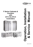
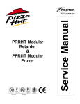
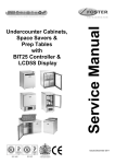
Probe Identification
The air probe fitted to this controller is the 10k NTC type (LAE SN4K15P1 Part number 00-556187).
The evaporator probe fitted to this controller is the 10k NTC type (LAE SN4K15P2 Part number 00-556188).
100
T1 Air Probe
T2 Evaporator Probe
100
50
LAE Probe Manufacturer
06-08 Date of Manufacture (Month/Year)
SN = NTC Device
ST = PTC Device
13
50
1K – 1k
2k – 2K
4k – 10k
15 = 1.5mts Long P1 Probe 1
20 = 2mts Long
P2 Probe 2
35 = 3.5mts long P3 Probe 3
AT1-5 & AT2-5 Wiring Diagrams
Technical Data
Power Supply AT2-5…E 230Vac±10%, 50/60Hz,
3W
Relay Output
AT1-5.S5 (6)...Compressor 16(8) Amp
Auxiliary Loads 7(2) A 240vac
Maximum total current 16A
Input NTC 10KΩ@25°C, LAE part No. SN4...
Measurement Range
-50…120°C, -55…240°F
-50 / -9.9…19.9 / 80°C (NTC 10K Only)
Measurement Accuracy <0.5°C within the
measurement range
Operating Conditions -10 … +50°C; 15%...80% r.H.
CE - UL (Approvals and Reference norms)
EN60730-1; EN60730-2-9;
EN55022 (Class B);
EN50082-1
UL 60730-1A
Front protection
IP55
Power Supply AT2-5…E 230Vac±10%, 50/60Hz,
3W
Relay Output
AT2-5.S... Compressor 16(5) A 240vac
Evaporator fans 7(2) A 240vac
Auxiliary Loads 7(2) A 240vac
Maximum total current 16A
Input NTC 10KΩ@25°C, LAE part No. SN4...
Measurement Range
-50…120°C, -55…240°F
-50 / -9.9…19.9 / 80°C (NTC 10K Only)
Measurement Accuracy <0.5°C within the
measurement range
Operating Conditions -10 … +50°C; 15%...80% r.H.
CE - UL (Approvals and Reference norms)
EN60730-1; EN60730-2-9;
EN55022 (Class B);
EN50082-1
UL 60730-1A
Front protection
IP55
14
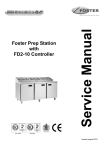
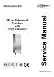
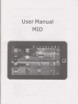
FXT601L Wiring Diagram - Integral Configuration with LD2 Controller Please note any wiring diagram not in this manual e.g for
remote units or units with lighting please see the Xtra Cabinets FXT601H & L, FXT1351H & L with LD1 & LD2 Controllers Wiring
Diagrams Manual.
15
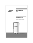
FXT601H Wiring Diagram - Integral Configuration with LD1 Controller
16
FXT1351L Wiring Diagram – Integral Configuration with LD1 Controller
17
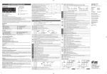
FXT1351H Wiring Diagram – Integral Configuration with LD2 Controller
18
Troubleshooting
Problem
Compressor will not start
Possible Cause
No voltage in socket
Electrical conductor or wires may be
cut
Defective electrical component:
thermostat, relay, thermal protector
etc
Replace defective component
Measure ohmic resistance of main
and auxiliary winding using
ohmmeter. Compare with correct
values
Compressor stuck
Change compressor
Controller is set at a very cold
position
Controller does not disconnect the
condensing unit
Control contacts are stuck closed
Defective or incorrect temperature
control
The temperature is not cold
enough
Use voltmeter to check
Use ohmmeter to check for
continuity
Compressor motor has a winding
open or shorted
Temperature control contacts are
open
Incorrect wiring
Fuse blown or circuit breaker
tripped.
Power cord unplugged
Controller set too high
Cabinet in defrost cycle
The temperature is too cold
Solution
Repair or replace the contacts
Check wiring diagram and correct
Replace fuse or reset circuit breaker
Plug in power cord.
Set controller to lower temperature.
Wait for defrost cycle to finish
Set to warmer position and check if
the compressor stops according to
controllers operating range.
Check the insulation of the
thermostat. If problem persists,
change the thermostat
Change the control. Check
amperage load
Determine correct control and
replace.
Controller is set at a very warm
position
Adjust to colder setting
Condenser is dirty
Clean condenser
The refrigerator has been placed at
an inadequate location
The unit must not be near stoves,
walls that are exposed to the sun, or
places that lack sufficient air flow.
Compressor is inefficient or there is
a high pressure due to the air in the
system
If there is air in the system, purge
and recharge
Iced up evaporator coil
Restriction in system
The refrigerator has been used
improperly
Too many door openings
19
Check temperature control,
refrigerant charge, and defrost
mechanism. Remove all ice
manually and start over.
Locate exact point of restriction and
correct
The shelves must never be covered
with any type of plastic or other
material that will block the circulation
of cold air within the refrigerator.
Advise user to decrease if possible
Excessive heat load placed in
cabinet
The refrigerator has been
overcharged with the refrigerant gas
The refrigerant gas is leaking
The evaporator and/or condenser
fans are not working
Blocking air flow
Fuse blown or circuit breaker tripped
Advise user not to put in products
that are too hot.
Check to see if condensation or ice
crystals have formed on the suction
line. If so, charge with the correct
amount of gas.
Find the location of gas leak in order
to seal and replace the defective
component. Change the drier.
Perform a good vacuum and
recharge unit.
Check electrical connections and
make sure that the fan blade isn‟t
stuck. Replace the fan motor if it
doesn‟t work.
Re-arrange product to allow for
proper air flow. Make sure there is at
least four inches of clearance from
evaporator.
Replace fuse or reset circuit
breaker.
Electrical Shocks
Wires or electrical components are
in direct contact with metallic parts.
Check for appropriate insulation on
the connections of each component.
Noise
The refrigerator is not properly
levelled
Check if the noise goes away after
you level the refrigerator
The condenser is not fastened
correctly. Copper tubing is in contact
with metal
The evaporator and/or condenser
fans are loose
Compressor has an internal noise
Loose part(s)
Extreme condensation inside the
refrigerator
The refrigerator had been placed at
an inadequate location
Set the controller to a warmer
position & check to see if
compressor stops as should.
This type of occurrence is caused by
local climatic conditions and not by
the refrigeration unit.
Check the door and/or the magnetic
gasket. Adjust the door hinges if
needed; replace the gasket if
broken.
The unit must not be near sources
that produce too much heat.
The light switch is “off” position
Press the light switch to “on” position
Controller is set at a very cold
position
The outside environment‟s relative
humidity is very high (over 75%)
The refrigerator door wont shut
completely
No illumination (Glass door
models only)
While the compressor is working,
check to see if metal parts are in
contact with one another and/or if
the screws that fasten the
condenser are tightened.
Check if the fans are securely
fastened. Also, check if the fan
blades are loose, broken or crooked.
If so, change the faulty blade.
If the noise persists after all other
measures have been taken, it may
be originating from the compressor.
Locate and tighten loose part(s)
False contact on the light switch, the
fluorescent tube, or the ballast
Light switch, ballast and/or
fluorescent tube are damaged
20
Inspect all connections
Replace the damaged component.
Condensing unit runs for
long periods of time
Excessive amount of warm product
placed in cabinet
Prolonged door opening or door ajar
Door gasket(s) not sealing properly
Advise user to leave adequate time
for products to cool down
Advise user to ensure doors are
closed when not in use and to avoid
opening doors for long periods of
time.
Ensure gaskets are snapped in
completely. Remove gasket and
wash with soap and water. Check
condition of gasket & replace if
necessary
Dirty condenser coil
Clean condenser coil
Evaporator coil iced over
Unplug unit and allow coil to defrost.
Make sure thermostat is not set too
cold. Ensure that door gasket(s) are
sealing properly. Select manual
defrost and ensure system works.
Notes
21
Foster European Operations
France
Foster Refrigerator France SA
Tel: (33) 01 34 30 22 22. Fax: (33) 01 30 37 68 74.
Email: [email protected]
Germany
Foster Refrigerator Gmbh,
Tel: (49) 781 990 7840. Fax (49) 781 990 7844.
Email: [email protected]
Foster Refrigerator
Oldmedow Road
Kings Lynn
Norfolk
PE30 4JU
Tel: 0843 216 8833
Fax: 0843 216 4707
Website: www.fosterrefrigerator.co.uk
Email: [email protected]
a Division of „ITW (UK) Ltd‟
FXT601&1351/LD1&2/ATI/2-5/SM/re0311
22