1
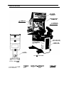
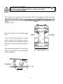
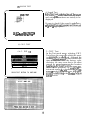
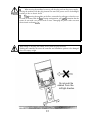
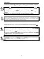
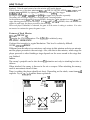
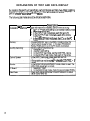
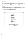
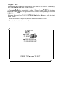
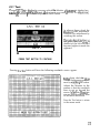
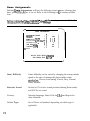
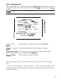
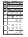
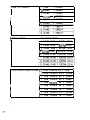
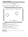
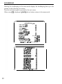
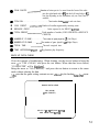
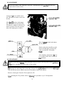
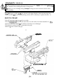
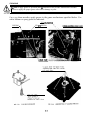
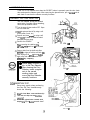
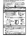
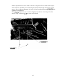
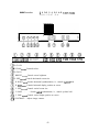
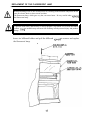
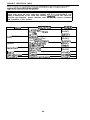
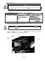
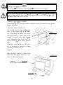
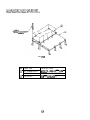
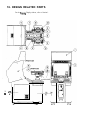
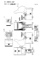
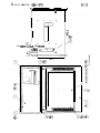
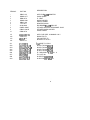
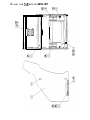
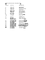
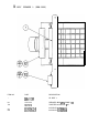
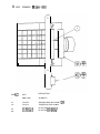
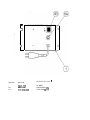
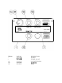
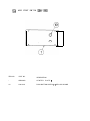
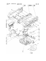
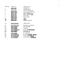
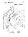
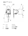
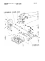
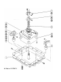
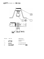
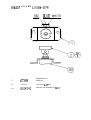
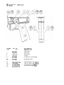
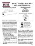
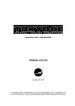
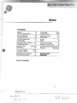
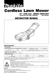
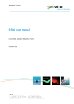
UPRIGHT
SERVICE MANUAL
SEGA ENTERPRISES, INC.
m;
-1
-1
MANUAL NO. 1201-6216-03
Contents
INTRO DUCT10 N 0 F THE OWNER’S MANU.iL
GAME REGISTRATION
GENERAL PRECAIJTIO NS
I~ST,\LLATIO N LO CAT10 N PRECXJTIO NS
S;\FETY hND REGULATORY INFORMATION
SPECIFICATIONS
INST,\LLATIO N ITEMS
<ASSEMBLING THE MACHINE
LEG ADJUSTERS
ASSEMBLY CHECKS
0 PER.XTIO N
HOW TO PLAY
EXPL.ANATIO N 0 F TEST AND DATA DISPLAYS
SWITCH UNIT
TEST MO DE
MEhlO RY TEST
INPUT TEST
0 UTPUT TEST
SOUND TEST
CRT TEST
G&ME ASSIGNMENTS
CO IN ASSIGNMENT
CO IN CREDITS
MANUAL SETTINGS
.AIM SET
60 0 KKEEPING
BACK UP DATA CLEAR
SERVICE INFORMATION
CONTROLLER
VR .ADJUSTMENT
TRIGGER SWITCH
MICRO SWITCH
MOT0 R BRUSH
GRE;\SING
CO IN SELECT0 R
MO NIT0 R CARE AND ADJUSTMENT
STATIC CONVERGENCE ADJUST,MENT
NASA0 MO NIT0 R
FLU0 RESCENT LAMP
PER10 DIC INSPECT10 N
TROL’BLESHOOTINC
G.AME BOARD
G.&ME BOARD SERVICE RECORD
DESIGN REL.tTED PARTS
P.ARTS IDENTIFICATION
P.\RTS REPLACEhiENT RECORD
MANUAL COMMENTS
WIRING DI;\GRAM
3
4
;
6
7
8
9
10
II
14
15
16
Ii
18
19
20
21
22
23
24
25
26
27
29
30
31
32
33
34
35
36
37
38
39
41
42
43
44
45
48
49
50
52
85
86
07
Follow Insrmctions: AU operating and. use insrtucrions should be followed
Attachmena: Do not use attachments not recommended by the product manufacturer as they may CXI.W hazards.
Accessories: Do not place KS produo: on an unstable can, stand, tripod, bracket. or table. The pmduct may fail.
causing serious hjury to a child or adult. and !serious damage to the product. Use o~lly with a cart_ sand, nipcd, bracket or
table recommended by the manufacturer, or sold with the product. Any mounting of the product should follow the
manufacturer‘s instmctions. and should use only moundng accessories recommended by tie manufacturer.
Moving the Product: This product should be moved with care. Quick stops, excessive force, and uneven surfaces
may ciluse the product to o”ertum.
Ventilation: Slots and openings in the c;lbinet are probided for ventilation. to ensure reliable opemtion of the product
and to protect it from overheating; rhese openings trust not be blocked or covered. The openings should never be blocked
by placing the product in a built-in installation such as a bookcase or rack unless proper ventilation is provided or the
manufacturer’s insttuctions have been adhered to.
Power Sources: This product should be operated only from the type of power source indicated on the marking label.
If you are not sure of the type of power supply to your location, consult your loal power company. For prcducrs intended
~0 operate from batter paver or other source5, refer to the operating insttuctions.
Grounding or Iblarization: This product is equipped with a three-wire grounding-w plug. a plug having a third
(grounding) pin. This plug will only fit into ia grounding-type power outlet. This is a safety feature. If you are unable to
insert rhe plug into the outlet. contact your eletidan to repkce your obsolete outlet Do not defeat the safety purpxe of the
~~ounding-type plug.
Power Cmd Protection: Power-supply cords should be routed so that they are not likely to be walked on or pinched
by items placed upon or against them, paying particular attention to cords at plugs, convenience receptacles, and the point
where rhey exit from the prcducr
Overloading: Do not overload wall oudets. exrension cords, or integral convenience receptacles as this can resulr in
a risk of fire or electric shock.
Object and Liquid Entry: Never push object, of any kind into this product through openings as they may touch
ciangerous voltage points or short-out parts that could result in a-fire or elecuic shock. Never spill liquid of any kind on rhe
prLxtun
servicing: Do not attempt to service this product younelfas opening or removing cowl-S may expose you to dangerous voltage or other hazards. Refer all servicing to qualified service pet3onnel.
Damage Reqobing Service: Unplug this product from the wall outlet and refer servicing to qualified se~%ce personuel under the loUowing conditions:
;ij lithe power cord or plug is damaged;
b) If liquid has been spilled, or objects have fallen into the product;
C) If the product has been exposed to rain or water:
d) If the product does not operate normally when following the operating insttxcdons. Adjust only those controls rhat
are explained in the opemtig insmxtiom. .&I improper adjustment of other controls may result in damage and will
often require extensive work by a qualitied technician to restore the product to its notmal operation:
e) If rhe product has been dropped or d:amaged in any way;
f) When the product exhibits a distinct (change in perfom~ance: this indiates a need for service.
RepL,-,a,t RX&E When replacement parts are required, be sure the setvicetechniti bar used re$WXtWnE panS
Fpecified by the manufacturer or that have the same characteristics a~ the original pm. Unauthotied substitutions may
.
resulr in tire. electric shock. or other hazards.
Safety Check: Upon completion of any sewice or repain to thii product. ask the ser-Ace technician to perform safety
checks to determine rhat the prcduct is in proper operating condition.
Heat: The product should be situated away from heat sources such ils radiators. heat registers, stoves. or other
p~~iucts (including amplifiers) that prcduce heat.
Cl.zmingz When cleaning the monitor glass, use water or glass cleaner and a soft cloth. Do not apply chemicals such
as bemine. thinner. etc.
Location: This an indoor game machiie. II3 NOT install it outside. To ensure proper usage. awid itwAling indoon
in the plnces mentioned below:
l
Places subject to rain/water le&qe, or condensation due to humidity;
l
In close proximity to a potential wet area;
l
Locations receiving direct sunlight:
l
Places close to heating units or hot air;
-In the vicinity of highly inflammable/volatile chemicals or hazardous matter;
l
0 n sloped sulfates:
l
I” the vicinity of emergency response facilities Such as fire exits and fire extinguishers;
l
Places subject to any type of violent itipact;
l
Dusty places.
INSTALLATION PIUXAUTIONS
l Verify the amperage of the branch circuit outlet before plugging in the power plug. Do not overload the circuit.
l
Avid using a” extension cord. If one is required. use a” extension cord of type SJT, 16/3 AWG
rated min. 120 VAC, 7.A.
l
Moving this unit requires a minimum clearance (of doors, etc.) of 32” (WI by 77” (H).
l
For tie o+adon of this machine, secure a minimum area of 32” (W) by 42’(D).
&CULATORYAPPROVM.S
This game has been tested and found to comply with the Federal Communications Commission Rules.
This device complies with F%t 15 of the F’CC Rules. 0 peration is subject to the following two conditions: (I) This
device may not cause harmful interference, and (2) this device must accept any interference received, including interfere”ce that may cause undesired operation.
This gdme has been tested and listed by Undetiten Laboratories, In;., to ANSUUL22.
LISTED
SK92
AMUSEMENT MACHINE
6
SPECIFICATIONS
BILLBOARD
29 INM WNI'TOR
n
n
FIG. 3 a
OVER VIEW
FIG. 3 b REAR VIEW
.4SSEiMBLED GAME
YVllJIH
LENGI’H
HElGHl
$8 IN
73 IN
W EItiHl
89 IN
662 LBS
INSTALLATION ITEMS
The following items are supplied with the machine. Be sure that these items remain
with the game if it is transported or sold.
1
1
1
1
Service !vfanual, Gun Blade NY
Tamperproof wrench, M4
Tamperproof wrench, M5
Remote Controller, Mitsubkhi Projection TV
8
ASSEMBLY AND PRECAUTIONS
Perform the assembly work by following the procedure stated herein. Failing to comply with
the instructions can cause an injury or electrical shock.
18
,Assembly should be performed as per the instructions in this manual. This is a complex
machine and erroneous assembly c;m cause electrical shock or damage to the machine resulting in
undesirerl operation.
8
When assembling the machine, be sure that more than one person is available to perform the
work. Depending on the assembly work, there are some cases in which performing the work alone
8
When carrying out the assembly work, follow the procedure in the following
sequence:
1
Securing in place (leg adjusters)
2
Power supply
3
Assembly check
Make sure that all the leg adjusters are in contact with the floor. If
can move, causing an accident
This machine has 4 casters and 4 leg adjusters. When the installation position has been
~-,I:..&-_,..
6,. LVIIICT
-,.-,.:-b.
_~_~^,.C..~~L
A-nuu,,
Ll,.,._~L,U
..-A,ILMC
-_,.__J’
~UJUJLCL> L”
U,L” C”IILALI_
w,u, u,e
duJUSf?
d
ments so that the casters are raised approximately 5mm from the floor. Ensure that the
machine is level.
Move the machine to the installation
sition.
po-
Cause all of the leg adjusters to make
contact with the floor. By using a wrench,
make adjustments in the height of the leg
adjusters to ensure that the machine is
level.
After making adjustments, fasten the leg
adjuster nut upwards to secure the height
of the leg adjuster.
\LEG ADlUSTER
10
Assembly Checks
MEMORY TEST
hr the test mode, perform the followmg tests:
1. Memory Test
Selecting the Memory Test on the test
mode menu screen causes the onboard memory to be tested automatically. The game board is satisfactory
if the dis lay beside each IC number
shows’280 D.
PRESS TEST RUTI-ON TO EXIT
INPUT TEST
2. Input Test
Selecting the Input Test on the test
mode m&u screen causes the screen
(on which each switch is tested,) to be
displayed. Press each switch. For the
coin switch test, insert a coin from
the coin inlet with the coin chute door
open. Ifthe display beside each s+,mh
indicates 0 N, the swatch and wu-mg
connecnons are sausfactory.
PLAYER
GUN x
mKii
COIN CHUTE #l
COIN CHl-l~,~
TEST
z
g
5
OFF
PRESS TEST BUTTON TO EXIT
3. Ou ut Test
In the 5p utputTestmode,mrryoutthe
lamp test to ascertam that each lamp
lights up satrsfactordy.
I
OUTPUT TEST
1P STAfiT LWP =ON
2P START LAW =OFF
1P GUN MOTOR =ON
2P GUN MOTOR =OFF
PRESS TEST BUllON TO WIT
(4)
SOUND TEST
/
Y
SoumTEST
4. Sound Test
IntheTestmode,selectingSoundTestcauses
the screen (on which sound-related board
and wiring connections are tested) to be
displayed.
Be sure to check if the sound is satisfactotil emittedfromeachspeakerandthesound
voIume is appropnate.
SELECT WITH SERVICE mJTroN
AN0 FRES TEST l3Ul-N
(5) C.R.T. TEST
C.A.T. TEST l/Z
0
31
PRESS TEST BUTTON TO CONTINUE
5. C.R.T. Test
In the Test mode menu, selecting C.R.T.
Test allows the screen on which the monitor is,tested) to be dis ayed. Although the
monitor adJu3ment.s ave been made at the
time of shipment from the factory, color
deviation, etc. may occur due to the effect
caused by geomagnetrsm, the location
bujldmg’s steel frames and other game machines on the periphery. By watchm the
test mode screen, d.eqde whether an.a 8Justmen! 1s needed. If tt IS necessary, adjust the
monitor by refernng to the Monitor Adlustments section.
A!
@
a!
When lifting or inclining the cabinet, do not hold the gun controller.
Holding the controller can cause the controller and installation portion to be damaged
due to the empty weight.
WARNEr’G
CAUTION!
When moving the machine, be sure to pull the plug out from the power supply.
Moving the machine with the plug inserted can cause the power cord to be damaged,
resulting in fire or electric shock.
FVhen moving the machine on the floor, retract the leg adjusters so that the cast@
ers come in contact with the flwr. During transportation, pay careful attention that the
casters do not tread over power cords or wires. Damaging the power cords can cause
short circuit or electric :shock.
Do not push the
cabinet from the
left/right direction.
,
OPERATION
To ensure safe operation of the product, be sure to comply with all the following precautions.
1 Be sure that all the leg adjusters are in contact with the floor surface. If they are not, the cabinet can
!
~ move and cause an accident.
A
4KVlXGi Do not put any heavy items on the pmduct Placing heavy items on the product on cause a accident.
Do not climb on the game. Climbing on the game can cause accidents as well as damage to the
controUer and other parts- To inspect the upper portion of the game, use a sturdy step or ladder.
i To avoid electric shock, check to see if door and cover parts are damaged or omitted.
To avoid accidents, he sure to provide a sufficient space for operation by considering the most
crowded situations. Insuff?ient space for operation can cause customers to come in contact with the
!
!I
\UTION! moving parts of the game and hit each other, resulting in injury.
To avoid injury and trouble, be sure to pay careful attention to the behavior of players and
visitors.
To avoid electric shock and short circuit, do not allow customers to put hands and fmgers or extxaneous matter into openings of product or small openings in and around the doors.
!~
!A
To avoid falls or injuries, prevent customers from leaning on or climbing on the game.
JMh’G!
To avoid electric shock, do not allOw the customers to unplug the power plug without good reason.
To avoid injury resulting from falling ejects or electric shock due to spilled liquids, do not allob
cutomers to place heavy items or drinks on the machine.
!!
1
UTION!
:mmediately stop such violent acts as hitting and kicking the product Such acts can cause damage to
,ans or breakage, resulting in injury from falling fragments.
14
HOW TO PLAY
Insert coin(s). When the number of credits needed for game play are available, “PRESS ST;\RT” is
displayed. Press the start button to have the mission select screen appear.
Choose from one of the three missions, F33XIN THE UN HQ, BIG APPLE LIBER;\TIO N, and
SC0 RE ,YfTACK REMIX, by sighting the desired one and pulling the trigger.
Moving the sight with the corm-oiler and pulling the trigger fires projectiles repeatedly.
The enemy who is trying to shoot you is indicated with a warning marker.
In the missions except SC0 RE ATTACK REMIX, destroying ail the enemies in a stage clears that
stage, allowing procession to the next stage. In the SC0 RE ;\TTACK REMIX, when one minute has
elapsed in each stage, the player proceeds to the next stage.
When each player’s endurance is exhausted, the game is in the status of waiting to continue. If no coins
are inserted to continue the game, the game is over
Features of Each Mission
REGrlIN THE UN HQ
To regain the UN headquarters. The difficulty is relatively easy.
BIG APPLE LIBERATION
Confront the terrorists to regain Manhattan. This level is relatively difficult.
SCORE ATEICK REMIX
Different from the above two missions, each stage in this mission ends in one minute
and the player proceeds to the next stage. Also, note that in this mission, which stage the
player proceeds to after finishing a stage depends on the score earned in the stage that
was finished.
Advice
The enemy’s projectile can be shot down. Pay attention not only to attacking but also to
defense.
When attacked, the enemy is thrown in the air or escapes. When attacking the enemy,
read its movements ahead of time.
There is nothing the player should not shoot. Depending on the attack, some items will
explode. Try to effectivly utilize these explosions.
MISSION TILE
\
’ 8J.67
12.50
&QwcE
STAGE TlME
EFDLFNCE
EXPLANATION OF TEST AND DATA DISPLAY
Byoper~tingtheswitd-~unit, pckdicAlypaformthet&saxldaache%. Wf~~instdlicg
themshineinitidly, orcdl&ingcash, or whentherrrAinedOgr0tfuncticn properly,
@arm ckdcs in arxknce with this c&ion.
Items
lnstdlation of M&ine
Descrlptron
Wlxn h e n - & ~r&&d psformthefoll
1. ChLtosZ%ZSseftkgisp5fstxdAwZCgm&
& thetirreof shipmmt.
2. IntheINFUTt&rtx& d-&erfiSWxdVR.
3. IntheCUTFUTt&n-cde, ckbexhof thelarps,
t-rotors, etc.
4. IntheMEMCRY t&mode, ~theICsonthePC
~83 yet, d-d the CCI’ITRCL s
I
WARNING!
I
Do not touch places other than those specified. Touching places not specified
can cause an electric shock or short circuit.
Ii
0 pen the coin chute door and the switch unit shown will appear. The functioning of
each SW is as follows:
TESTBUTTON
SERVICE BUTT0 N
SPEWSER VO LLJME
suPERwooFERvoL
COINMETER
For the handling of the test button, refer to the
following pages.
Gives credits without registering on the coin meter.
Can adjust the volume of all speakers of the machine.
By considering the envirdnmental aspects of the
installation location, adjust to the appropriate sound
volume.
0 nly the sound volume of the cabinet superwoofer
can be adjusted.
Registers total number of coins.
Test Mode
The Test Menu allows the functioning of each part of the Cabinet to be checked, the
monitor to be adjusted, and the coi~ns and game related vanous setttngs to be performed.
’ Press the Test Button to cause the following Test Menu to be displayed on the monitor.
’ Press the Service Button until the arrow -) is moved to the desired item to make a
selection
’ Bring the arrow -) to the desired item and press the Test Button to enter the selected
items test.
’ Choosing EXIT and pressin theTest Button will finish the test mode, and the game
mode returns on the screen 2ter networkcheckmg.
MEMORY TEST
INPUT TEST
DUTPUTTEST
SOUND TEST
i.R.T. TEST
GAME ASS I GNMENTS
COIN ASSIGNMENTS
AIM SET
BOOKKEEP I NG
BACKUP DATA CLEAR
> EXIT
SELECT WITH SERVICE BUTTON
AND PRESS TEST BUTTON
.
18
/
Memory Test
The Memory Test mode is for checkin the on-board memory 1C functioning. GO 0 D is
5. lsplayed for abnormal ICs.
displayed for normal ICs and BAD IS
’ When the test is completed, if the results are shown as adjacent, it is satisfactory.
’ When the test is not finished, IC Board malfunctioning may be the cause.
’ ;\fter finishing the test, press the Test button to return to the Menu mode.
MEMORY TEST
ICO9 GOOD
IC12 GOOD
lCl0 GOOD
IC13 GOOD
lCl1 GOOD
IC14 GOOD
IC79 GOOD
I C82 GOOD
IC88 GOOD
IC80 GOOD
I C 8 3 GOOD
IC89 Go00
IC81 GOOD
IC84 GOOD
P R E S S T E S T BU-ITON TO EXIT
Input Test
When InputTest is selected, thqmonitor will sho,w the following, allowin you to watch
the status of each swatch. 0 n thts screen, pertodtcally check the status o tgeach switch.
’
on the right-hand side of the name of each switch
and the wmng connections are sausfactory. When
the dtrectton of the arrow, the right-hand side
name becomes 0 N.
’ To check Coin Chute#l and Coin Chute%2 Coin Switches, open the Coin Chute Door
and insert coin(s) into the slot.
’ To return to the Menu mode, press the Test button.
INPUT TEST
PLAYER
GUN X
Y
TRIGGER
START
CO I N CHUTE #1
COIN CHUTE #2
SERV I CE
TEST
1P
80H
80H
OFF
OFF
OFF
OFF
OFF
OFF
2P
80H
80H
OFF
OFF
PRESS TEST BUSTON TO MIT
GUN
X
: Under 30H + Over dOH
right
left
GUN
Y
:
Under 60H - Over bOH
down
“P
Output Test
Selecting 0 utputTest allows the status of each lamp to be viewed. Periodically
check the status of each lamp on thus screen.
lays sequentially in order of Winner Lamp, 7-SEG. At this time
LED tests are performed in the manner corresponding to the item
This game does not have 7-SEG LED. During the display of ‘I-SEG, only the Start
button flashes.
’ While this screen is displayed, the Start button continues to flash.
a Press the Test button to return to the menu mode.
f
OhPUT TEST
1P START LAMP =ON
2P START LAMP =OFf=
1P GUN MOTOR =ON
2P GUN MOTOR =OFF
PRESS TEST BUITON TO EXIT
Sound Test
Selecting Sound Test allows sounds (sound effects, announcement, background music,
etc.) to be chosen and heard. In this mode, check the sound-related IC Board and each
s eaker. Press the Service button to brin the arrow--> to the desired sound item. Press
ti!e Test button to have the selected SOW-I 2played. Each time the Test button is pressed, the
next sound 1s played.
VOICE
ERECT
B.&M.
> EXIT
:
:
:
:
SELECT’ WITH SERVICE BurrON
AND PRESS TEST BUTTON,
22
CRT Test
CRTTest to displa the screenpn which the Monitor ad’ustment is checked. Bv
watchin the screen, F eno d:
~cally check lf adjustments are neede d or not. For adjustmenl,
refer to !h e Secuon o Monitor Adjustment stated herein.
Choose
In adjacent figure, check the
Momtor’s color adjustment.
Perform color adjustment by
watchmg this screen.
Thecolorbarof4colors,i.e.
red, green, blue and white is
darkest at the left end and
becomes brighter towards the
nghtend.
WHITE !
0
31
PRESS TEST BUTTON TO CONTINUE
Pressing theTest button will have the following crosshatch screen appear.
In thjs figure, check the Zv!onitor size and posmon adjustment by watchmg the screen.
Adjust the Monitor in the
manner so that the crosshatch
lines to not go beyond the
screen. Adjust the Momtor to
ensure thatcrosshatch lines
do not have distortions.
Press the Test button to return
to the menu mode.
23
Game Assignments
Selecting Gqe Assignments will have the following screen a pear, allowing play
time, game dtfficulty, etc. to be set. Refer to the following fort f: e contents of each
item.
the se ‘q wi not be than ed. Be sure to press test to Exit after
3F.&JZ~ti5Atung. %r5wi#store your Atings.
I
GAME ASSIGNMENTS
: [
ADVERT1 SE SOUND
:[
COUNTRY
GAME D I FF I CULl-Y
: [
S H I F T I N G DIFFICULM : [
PLAYER LIFE :
i ;
GUN REACTION
:(
C A B I N E T TYPE
> EXIT
XX&
4/0
4/8
3
ON
DX
SELECT WITH SERVICE BUITON
AND PRESS TEST BUTTON
“4
Game Difficulty
Game difficulty can be varied by changing the enemy missile
speed or the ratio of damage the player suffers when
attacked,etc. Choose from among 4 levels, Easy, Normal,
Hard, Hardest
Advertise Sound
Set this to 0 N to have sound produced during Demo mode,
and 0 FF for no sound.
Country
Message language. Select USA for USA and Export for
other countries.
Cabinet Type
Set to Deluxe or Standard, depending on which type is
applicable.
Coin Assignments
This mode permits vou to set the start number of credits,.as well as the basic numbers of
coins and credits. This mode expresses “how many cams correspond to how manv
credits”.
Sgtting change is not effective until Exiting. Be sure to Press test to Exit after setting
c ange.
COIN ASSIGNMENTS
COMMDN . . . . . . .
COIN CHUTE TYPE
2 CREDITS .
CREDIT TO START
1 CREDIT..
CONTINUE
2PLAYER CREDIT TO START 2 CREDITS .
C O I N / C R E D I T SETTING #l
C O I N C H U T E $1 1 COIN 1 C R E D I T . . . .
COIN
.
.
.
.
.
.
.
.
.
.
.
.
.
.
.
.
.
.
.
.
.
.
.
.
...... .
C H U T E #2 1 C O I N 1 C R E D I T . . . . . . . . . .
MANUAL SElT’ING..........................
I
.. 2%
> EXIT
Gl
.@
.
a
SELECT WITH SERVICE BUl-l-ON
AND PRESS TEST BUTTON
Credit to Start
game.
Sets the number of credits required when starting the
Credit to Continue
Fme.
This sets the number of credits required tocontinue
Coin/Credit Setting How many coins correspond to how many credits. In this
machine, selection as per the adjacent chart IS posstble.
Maryal Setting
Allows for finer settings. See chart
1, Press the Service button or Shift button to bring the arrow to the desired change
item.
2. Press the Test button or the Start button to select the setting change item.
3. Move the arrow to Exit and press the Test button or the Start button to return the menu
mode to the screen.
TABLEB. 10a COIN/CREDITSKTING (COIN CHUTECOMMONTYPF)
COIN CHUTE #I
I CREDIT
2 CREDITS
3 CREDITS
4 CREDITS
5 CREDITS
2 CREDITS
FUNCTIONING COIN CHUTE #2
I COIN
1 CREDIT
I COIN
1 CREDIT
I COIN
1 CREDIT
I COIN
I CREDIT
I COIN
I CREDIT
I COIN
2 CREDITS
I COIN
I COIN
r COIN
2 COINS
I COIN
I COINS
-i- COIN
2 COINS
-i- COIN
5 CREDITS
3 CREDITS
4 CREDITS
5 CREDITS
6 CREDITS
I CREDlT
I CREDIT
2 CREDITS
I CREDIT
3 CREDITS
3 : CREDITS
-SETTING #Xl
3 COINS
4 COINS
I COIN
2 COINS
3 COINS
4 COINS
I COIN
I
I
I
2
3
5
5
SETI’ING #2i
SETTING W22
5 COINS
- I - COIN
I
I
I
I
I
2
2
2
I
2
I
2
3
4
I
2
3
4
I
2
3
4
SETTING
SETTING #I
SETTING Y2
SETTING #3
SETTING #4
SETTING ff5
SETTING #6
SETTING #7
SETTING #X
SEl-TlNG 119
SETTING #IO
SETDNG #I I
SET-TlNG
SETTING
SEI-TING
SETTING
#I2
813
#I4
#IS
SETTING #I6
SETTING #I7
SETTING #IX
SE’I-TING #I9
SETTING #23
s.Erri rcic#?4
._
SETTING #25
SETTING #26
-SETTING #27
26
FlJffCTlONlNG
I COIN
I COIN
I COIN
I COIN
I COIN
I COIN
-i-. COIN
1 COIN
2
4
S
7
COINS
COINS
COINS
COIN
CREDIT
CREDIT
CREDIT
CREDlTS
CREDLTS
CREDITS
CREDITS
_...,,_
I CREDIT
2 CREDITS
I
2
3
3
5 COINS
3 COINS
CREDIT
CREDITS
CREVITS
CREDlTS
1
5 COINS
2 COINS
4 COINS
S , COINS
2 COINS
4 COINS
5 COINS
2
3
4
5
6
CREDITS
CREDITS
CREDITS
CREDITS
CREDITS
I
I
l
I
3
CREDIT
CREDIT
CREDIT
CREDIT
CREDITS
I
3
I
I
I
2
3
5
I
2
3
5
I
I
CREDIl
CREDITS
CREDIT
CREDIT
CREDIT
CREDITS
CREDITS
CREDITS
CREDIT
CREDITS
CREDITS
CREDITS
CREDIT
CREDIT
2
I
2
3
I
2
3
1
2
3
4
CREDITS
CREDIT
CREDITS
CREDITS
CREDIT
CREDITS
CREDITS
CREDIT
CREDITS
CREDITS
CREDITS
CREDITS
CREDIT
CREDITS
CREDITS
CREDITS
CREDITS
COIN
2 COINS
3 COINS
4 COINS
I
2
3
4
5
COINS
6 CREDITS
5
COINS
COIN
6 CREDITS
1
2
3
4
COIN
COINS
COINS
COINS
6
I
2
3
4
5
COINS
6
I
I
CREDIT
CREDITS
CREDITS
CREDITS
COIN
COIN
COIN
COIN
COIN
COINS
COINS
COINS
COIN
COINS
COIN
colivs
COINS
COINS
COIN
COINS
COLNS
COINS
COIN
COINS
COINS
COINS
1
4 COINS
1
FREE PLAY
I COIN
2 COINS
3 COINS
I
FREE PLAY
-
MANUAL SETTINGS
/
Y
COIN ASSIGNMENTS
MANUAL SETTING
COIN TO CREDIT 1 COIN 1 CREDIT . . . . . .
NO BONUS ADCER . . . . . . . .
BONUS AC034
C O I N C H U T E #l MJLTIPLIER
1 C O I N COUM-S A S 1 C O I N .._....
C O I N C H U T E #2 MULTlPLlER
1 COIN COUNTS AS 1 COIN . . . . . . .
> EXIT
. . . .
.... %
. . . .
OD
.... 0
SELECT WITH SERVICE BUlTON
AND PRESS TEST BUlTON
.
/
8 . . . . . . . . . . . . . . . . . . . . . . . . . . . . . . . . . ..- Determines conversion of coin/credit.
9 . . . . . . . . . . . . . . . . . . . . . . . . . . . . . . . . . . . . . . . This sets how many conversion coins should be inserted to
obtain one service coin.
10 . . . . . . . . . . . . . . . . . . . . . . . . . . . . . . . . . . . This sets how many conversion coins are represented by a
coin inserted in coin chute one.
1 l..................................... This sets how many conversion coins are represented by a
coin inserted in coin chute two.
[COIN TO CREDIT
I
1 1 COIN
2 COINS
3 COINS
4 COJNS
1
1
1
1
CREDIT
CREDIT
CREDIT
CREDIT
5 COINS
1 CREDIT
/ 6 COINS
1 CREDIT
I
NO BONUS ADDER
2 COINS GIVE 1 EXTRA COIN
] BONUS ADDER
3 C O I N S G I V E 1 fZXTRA C O I N
4 COINS GIVE 1 EXTRA COIN
j 5 COiNS G I V E 1 E X T R A C O I N 1
1 6 COINS GIVE 1 EXTRA COIN 1
C O I N C H U T E M U L T I P L I E R 1 1 COIN COUNTS AS 1 COIN
I
11 C O I N C O U N T S A S 2 C O I N S 1
I
I
I
I
/ 1 COIN COUNTS AS 3 COINS
1
1 1 COIN COUNTS AS 4 COINS
/
1
/
1L
1
1
1
/I
1
1
1
1
1
COIN
COIN
COIN
COIN
CCiJNTS
COUNTS
COUNTS
COUNTS
AS
AS
AS
AS
5
6
7
8
COINS
COINS
COINS
COINS
/ 1 COIN COUNTS AS 9 COINS /
AIM SET/GUN CALIBRATION
The test menu allows the functioning of each part of the cabinet to be checked. Gun
calibration is performed from the “Aim Set”screen.
Press the test button to cause the test menu to be displayed on the monitor.
Press the service button until the arrow (>) is moved to Aim Set.
Press the test button to enter the Aim Set mode.
PULL 1P OR 2P TRIGGER TO START 1P OR 2P AIM SET
PRESS TEST BUTTON TO EXIT
Setting Procedure
Pull the 1P (left player) gun trigger one time and release.
The left gun cursor will disappear off the screen. ,
Move the 1P gun fully to all of its mechanical stops (all directions).
Pull and release the 1 P gun trigger again to store the settings.
The left gun cursor will then reappear.
Perform the same procedure on 2P gun (right player).
Press the test button to have the menu mode return to the screen.
MPOR-IAV-I-!
The above procedure must be performed each time the aim set test is entered to assure
proper game PRY.
BOOKKEEPING
Selecting the bookkeeping in the menu mode displays the bookkeeping data up to the
present on the following two screens.
Press the test button again to proceed to the next screen.
When screen 2/2 is displayed, pressing the test button returns to the menu mode.
.
f
BOOKKEEPING l/2
0
COIN CHUTE #l
COIN CHUTE #2
:
TOTAL COIN
C O I N CFEDIT
:
S E R V I C E C%DlT
0
TOTAL CFlED I T
0
NUMBER OF 1P GAME
NUM8Eft O F 2P GANE
i
NUMBER OF G&ME
0 0 O H ou OS
TOTAL TI ME
O H OM OS
PLAY TIME
O H DM O S
AVEFWE P L A Y T I M E
O H ON OS
L O N G E S T PLAY TIME
OH OM OS
SHORTEST PLAY TI ME
PF!ES.S TEST BUl-fON T O C O N T I N U E
Y
WCKKEEf’Iffi Z/2
01129s . . . .
Zif%” -’ smGRAll
CllluOS - ok59s . . . .
1M OS - lM29S . . . .
lU3OS - lffi9S . . . .
i!Y OS - m24s . . .
:
0
3w9s : : : :
ilM3OS
3M OS - 2M59S
31130s - 3M59s I . . .
i
’ 0
:
4U59s . . . .
~:
4iU
4U3OS
OS - 4W9S
fiU OS - su29s . . . .
:
w3os - 5M59s . . . .
ciu OS - 6w29S . . . .
:
6Y3OS - 6y59S . . . .
i’tl OS - 7u29S . . . .
:
7M3os - 7us9s . . . .
8~ OS - 81129s . . . .
i
w3oS .- 8Ms9S . . . .
9M OS - 911129s . . . .
9M3os - 9M59s . . . .
!
....
1011 OS ‘PRESS TEST 6WTCN TO EXIT
0
COIN CHUTE- _.._..._............... Number of coins put in. As seen from the front of the cabi-
net, the right-hand side is #l and the left- hand side is #2.
Note that depending on the destinations, only one Coin Chute is
available.
0 TOTAL COIN . . . . . . . . . . . . . . . . . . . . . . . . . . . . . . Total number of coins injetted in each coin chute.,
l COIN
CREDIT . . . .._..................... Number of credits registered by inserting coins
l
SERVICE CREDIT . . . . . . . . . . . . . . . . . . . . Credits registered by the SERVICE BU?TON
a
TOTAL CREDIT ._..............,........ Total number of credits (COIN CREDITS •t SERVICE
0
NUMBER OF 1 P GAME . . . . . . . . . . . . The number of game played by 1P (Left Player).
0
NUMBER OF 2P GAME . . . . .._...... The number of game played by 2P (Right Player).
a
TOTAL TIME . . . . . .._.....................~ The total energized time.
0
TIME HISTOGRAM ..___.___. . . . .._ By-playtime play frequency.
CREDITS)
BACK UP DATA CLEAR
Clears the contents of bookkeeping. When clearing, use the service button to bring the
arrow (>) to “YES (CLEAR)” and press the test button. When data has been cleared,
“CO MPLETED” will be displ.ayed.
Bring the arrow to “NO (CANCEL)” and press the test button to return to the menu
mode without clearing the data.
.Aso. note that the game setting contents are not affected by the backup dataclear operation.
BACKUP DATA CLEAR
YES (CLEAR)
> NO (CANCEL)
S E L E C T WITH S E R V I C E RJlTCf’4
AND PRESS TEST EUlTON
/
/
31
CONTROLLER
In order to prevent an ele&c shock and short circuit, be sure to turn off power before per!
A
WARMKi!
forming work that requires you to touch the interior of the product.
Be careful SO as
,not to damage any wiring. Damaged wiring can cause an electric shock or
short circuit acddent.
In the test menu, when the controllers VR
values can not be adjusted to the allowable range, it is necessary to adjust the
VR installation position or replace the
VR. ;\lso, be sure to apply grease to the
mechanism every 3 months.
To perform the above mentioned work,
remove the controller from the cabinet
When performing this work, also redove
the side cover and mechanism side cover.
-1
I
TWERPROOF 9XmS
(11
Removing the Side Cover and Mecha
Side Cover
By taking off a tog of 8 screws, remove
the side covers L and R.
By taking off a total of 11 tamperproof
screws, remove the mech side cover L and
R.
Take off the two screws to remove the
Hide Plate.
n!uss SCREWS (4)
MX 12, chrdme plated
FlA’llQQ SCRD (2;
. SiDE COVER
TRUSS mms (3)
M4XX5. chrome p l a t e d
32
VR ADJUSTMENT
Do not touch places other than those specified. Touching places not spedfied can cause an
!
/\
electric shock or short circuit.
WARNIN!
Loosen the 2 screws which secure
the VR bracket in order to move the
bracket.
Move theVR bracket to disengage
the adjust gear mesh and move the
VR shaft in a manner so that the VR
shaft cut portion faces the opposite
side of the adjust gear as shown.
Have the gears meshed and tighten
the two screws.
Slowly swing the controller up and
down, left and right to check if the
value exceeded the VR mobile
After finishing adjustments, be sure
to set sights on the aim set screen in
the test mode.
VR REPLACEMENT
!
A
,
” order to prevent an el&c shock and short circuit, be sure to turn off power before perform-
mg work by touching the interior parts of the product
WARNIIGG! _
By removing the cord clamp, first remove the VR blue 3P for @down and VR red 3P for leftfright.
Take off the two screws which secure the VR bracket to remove the bracket.
Remove volume gear from the VR to replace the VR.
.lfter replacing the VR, perform work by following the procedure as per VR adjustment
33
REPLKEMENT OF TRIGGER SW
In order to prevent an electric shock and short circuit be sure to turn off power before perfo&g
work which involves touching the interior of the product.
,~~vNG! ( Be careful so as not to damage wiring. Damaged wiring can cause an electric shock or short
1circuit accident.
Mhx~ the trigger is pulled, if0 N is not shown in the trigger display in then test menu input test
screen. the micro SW may be malfunctioning. In that case it is necessary to replace the micro SW
RE??OVINGTHEGRLP
Take off 7 tamperproof screws X and cover right.
Take off 5 tamperproof screws A and remove the cover left with cover bracket attached to it. &y
attention to the wires attached to the bracket so that they are not damaged.
Disconnect the connector which is connected to the g-tip.
Remove 6 U nuts to remove the grip.
TAK’ERPROOF S’XY A (7) 1
REPLACING THE MICRO SWITCH
Take off two tamperproof crews A and 3 ramperprwf screws B to remove the Grip Right.
In this status, the micro switch can be replaced.
TAMPEZPRCOFSCREWB
(3)'
35
REPLACEMENT OF MOTOR BRUSH
On the output test
screen in the test
mode, when 1P gun or
2P gun display indicates 0 N, if the gun
does not vibrate, first
check the switch unit’s
circuit protector. If
the circuit protector is
satisfactory, check the
motor brush.
By referring to the
figures below, remove
the cover left, cover
right and the grip.
Remove a total of 6 U
nuts to withdraw the
slide mecha. Pay
attention to the wirings to remove the
connector.
Take off the two
screws from the lower
part of the motor to
remove the brush. If
the motor brush is
worn away as shown,
replace the motor
brush. When replacing the brush, be sure
to replace brushes for
both sides simultaneously.
I%. Y. 5
36
b
CREASING
Be sure to apply grease to specified parts as indicated in the periodic maintenance schedule.
Failure to apply the proper grease can result in damage to parts.
0 nce every three months, apply grease to the game mechanisms specified below. Use
white lithium or spray grease as indicated.
V.R. CUR FQ%TIoN
SLIDE RAIL
\
/
GUN DRIYE PORTION
HANDLING THE COIN JAM
If the coin is not rejected even when the REJECT button is pressed, open the coin chute
door and open the selector gate. After removing the jammed coin, put a normai coin in
and check to see that the selector correctly functions.
1 CLEANING THE COIN SELECTOR
1
The coin selector should be cleaned
once every 3 months. When cleaning,
follow the procedure below:
Turn the power for the machine OFF. Open
the coin chute door.
@en the gate and dust off by using a soft
brush (made of wool, etc.).
Remove and clean smears by using a soft
cloth dip@ in water or diluted chemical
detergent and then wrung.
Remove the CRADLE.
When removing the retaining ring
FIG.
10 a
(E ring), be vety careful so as not to bend
the shaft.
Remove stain from the shaft and pillow
ponicns by wiping off with a soft cloth, erc.
After wiping off as per@ above, funher
apply a dry cloth. etc. to cause the coin
selecror 10 dry completely.
0 Never apply machine oil,
etc. to the Coin Selector.
0 After cleaning the Coin
Selector, insert a regular
coin in the normal
working status and
ensure that the Selector
correctly functions.
FIG. IO b
COlti INSERTION TEST
Once every month, when performing
the Coin SW Test, simultaneously
check the following:
Does the Coin Meter count satisfactorily?
Does the coin drop into the Cashbox
corrccrty?
Is the coin rejected when inserted while
keeping the Reject Butran pressed down?
FIG. 10 c
CAUTIONS AND WARNINGS CONCERNING THE SAFETY
FOR HANDLING THE MONITORS
Before handling the monitors. be sure CO read the following explanations and comply with the caution/
warning instructions given below. Note that the caution/warning symbol marks and letters are used in the
instructions.
i
Q
W*RMHO
n
!
#*“NUIG
Indicates ihat handlinp the monitor erroneously
by disregarding this warning may cause a
potentially hazardous situation. which could
A !~
result in death or serious injury.
uuwzu
indicatea that handling the moniton by disrcgarding this caution may cause a potentially
hazardous situation. which could result in
personal injury and or material damage.
Indicates that access to a specific part of the
Indicates ti ilutmction to d&connect a power
equipment is forbidden.
cormector or plug.
l When perfonninp such work as installing and removing the tmoitox. ioaerting aad disconnecting the
external connectors to sod from monitor interior and the monitor, be sure to di scooacct the power co”“ec
tar (plug) befotv starting the work. Proceeding the work without following this instruction can cause
shock or malfunctioning.
0 Using the monitor by converting ir without obtaining a prior permission is not allowed.
be liable for any malfunctioning and accident caused by raid convenioo.
SEGA shall not
0 Primary ride and Secondary side
The monitor’s circuit which is divided into the Primary side and
!
sccondaty side. is insulated. Do not touch the primary side. or
n
y*R)1m do not touch both the primary side and the secondary side
simultamusly. Not following the:instruction caocause shock
and this is very dangerous. When making monilor adjustments, use a non-conductive driver and make adjustment
without touching any pan other than the Adjusrmcnt V. R. and
knob. Also, be sure not to cause a shortxitcuit to the Primary
side and Secondary side. If short-circuited, it may cause shock
or malfunctioning. which is very dangerous.
0 High-tension Voltage
Some of the pam inside monitor are subject to high-tension voltage in excess of 20.050 vohs and very
dangerous. Therefore, be sore not TO touch the monitor interior. Should soldering & papr wastes. etc. t*:
mixed in the monitor Interior, turn the power off so as not to cause malfunctioning or fire hazard.
FOCUS L!3D
SECONOARY S1D
n
1
:,‘,
l Connecting the CRT and PCB
For combining the CRT and I’CB. ILV the specified pan No. to maintain the statw of adjustments made nt
the factory. The anode of the CRT itself will be accumulatively charged as time elapses, generating hightension voltage which is very dangerous. llte monitor should be used with the Qlassis, CRT and PCB
asscmhied. When repair. etc. is required at the lime of malhrnctioning. be SUIT to send it in an “xs is
axxmhled” condirion. If these arc disaaricmbled. what’s charged to said high tension voltage can be
discharged. causing a very haztrdou situation. Therefore. under no circumstances should it be d&assembled.
0 Static Electricity
Touching the CRT surface sometimex causes you to slightly feel electricity. This is because :hc CRT
surfaces arc subject to static and will not adversely affect the human body.
0 Installation and removal
Ensure that the Magnetizer Coil. FBT (Fly-Back Traosfomte?), Anode Lead attd FOCUS Lead are not psitioncd close to the she& metal wotk’s sharp edges. etc. and avoid damaging the insulated portions so i~1 not
to ca~ce shock and malfunctioning. (For the name of pati. refer to the above Figurea).
CAUTION!
For the purpose of static prevention, special coating is applied to the CRT
face of this product. To protect the coating, pay attention to the following
points. Damaging the coating film can cause electric shock to the
customers. For the caution to be heeded when cleaning, refer to the
Section of Periodic Inspection Table.
l Do not apply or rub with
a hard item (a rod with
pointed edge, pen, etc.)
to or on the CRT
surfaces.
l Avoid applying stickers,
seals, etc. on the CRT
face.
0 Do not remove aluminum
foils from the CRT
corners. Removing the
aluminum foils can cause
static prevention effects
to be lowered.
40
Monitor adjustments have been made at the time of shipment. Do not make further adjustment-s without a justifiible reason. Adjusting the monitor and its high tension parts is dangerous. Also, erroneous adjustment can cause deviated synchronization and projeaion fault,
resulting in a malfunction.
When making adjustments, use a resiious alignment screwdriver. Servicing with a bare
hand or using a conductive tool can cause electric shock.
41
NANAO monitor:
2 0 O - 5 2 4 2 - 2 4 - O 4(24Kmode)
2 0 0 - 5 3 8 7 - 2 4
O@O@
O@O@@@
1RGAIN GG,ALY BGAIN BRIGHT
HSlZE. HHOLD HP3 VSEE VHOLD VFflSl
R-GAIN
’ G-GAIN __........ Controls colors.
B-GAIN
BRIGHT ..,._.,,__ Controls screen brightness.
H. SIZE ..,...,.... Controls horizontal screen size.
H. HOLD ,...,,.._ Provides horizontal synchronization, i.e., controls rightieft hold.
H. PO.51 ,,,......._ Controls horizontal display position on screen.
V. SIZE .,......... Controls vertical screen size.
V. HOLD . . . . . . . . . Provides venical synchronization, i.e., controls up-down hold.
V. POSI ..,,....._. Controls vertical display position on screen.
’ CONTRAST.... Adjusts image contrast.
42
REPLACMENT OF THE FLUORESCENT LAMP
WARNING!
When performing work, be sure to turn power off, Working on the machine with power on can
cause an electric shock or short circuit accident.
The fluorescent lamp, which gets very hot, can cause burns. Be very careful when rep!acing
the fluorescent lamp.
CAUTION!
To perform work safely and securely, be sure to prepare a step which is in a secure and stable
position. Usiig an unstable step can cause falls resulting in both personal injury and product
damage.
Remove the billboard holder and pull the billboard upward to remove and replace
the fluorescent lamp.
!
t/!Efi?E-
I
SAsi LmPEx
PERIODIC INSPECTION TABLE
Theitemlx4owreyireperiodicchxkzdrdnt~tor~~ntheprformaKzof
rnachineaxlmwesdebusimoper~im.
this
Be sure to dean the interior of the cabinet and inspect and dean the power
supply plug once per year. Using the cabinet with dust accumulated can
cause a malfunction or fire. Note that careless deaning work can cause an
accident and therefore, proper attention must be paid to ensure continued
safe operation of this product.
I rtrvs
Controller
Coi n Chute Tower
Monitor
GaneBcad
ntaior
Cabinet SHfzcz
Pnwcl Plllrl
I
rJtsCRl
Lamp al&
Trri=w witch Cl-i&
ng
ch& coi n witches
Coin In=tion Test
Coin sel&tor Ckming
ch& Adiustmcnts
sum atiing
Manory Test
SfdtirigCkck
ckming
awning
Inca32iondcIEEnir-ia
44
Ptnl ou
Monthly
Monthly
Quataly
Monthly
Monthly
Quarterly
Monthly
Weekly
Monthly
Monthly
Annudly
ASt-EdEd
Annudlv
TROUBLESHOOTING
!
/\
WARhTKG!
Ir
In order to prevent an electric shock, be sure to turn power off before performing work and /
touching the interior of the machine.
Be careful so as not to damage wiring. Damaged wiring C~II cause an electric shock or short
circuit accident.
1,
For troubleshooting, first check the
connection
of the wiring-connectors.
1 W MtASJHt
hrtiy rm33-t the&q into thecutlfk
M&esurem thepowtr supply
vdtsgg aecorre3.
First, rmetkeczimof
ovam-at, tke7 rqka the fuse
Fri mq Fusz 7A 25OV Fast 810
SfconQy Fuss zzVB;o Blo
CAUSt
Theaxdrsmtplqpxlm.
I name3 powa scudvoltage
Prirwv or SEmnday fuse
Mown.’
4A Fa;t Blo
I
REPLACEMENT AND ADJUSTMENT OF FUSES
Be sure to use fuses meetig the specified rating. Using fuses exceeding the s+eci rating
can cause a fire or electric shock.
,-\s shown in +e figures below, open the side door on the left hand side of the cabinet,
and the fuse appears in the positions shown.
I
TROUBLESHOOTING
Theitmslistglb&w will a&St in trcubkhootingwhenaproblmmrs. Asafirst skp, ckk
dl wiringamneXor cmne;tions&verify ACpowstotherrrxhine
TAECE~: TROUBLEWOING
. . ._-__...
During- projfdilesare
diSpkygi on thesum, but IX)
&ion of l&/ri@t gms
-. .- --
---._ .-.. . ..-..--..-
Thertiifier bcmdfuseisMown
dueto m instznta7exs
ovErlo&.
Aftcr flin-in&ngthacof the
ovmkl, rfplzcathe rcctifa bead
fuse
m
Fti6.4oxxl
ovcraxre-rt, thm r+ixthefuse
Frimy Fuse 7A 25OV Fast 610
a-d thefluorescent larp dog
not IicJt up.
Durirggmapl~, whf31
proj&ikaedispla@ on the
duetoalinstmtmexs
Themtorbrushgaewom
46
,
overcurrmt, restorethe
dfarit bre&er to its orignd
Rfpke motor brushes.
\RNNG!
In order to prevent an electric shtxk, be sure to turn power off before performing work and
touching interior parrs of the machine.
Be careful so as not to damage wiring and cause an electric shock or short circuit.
~ Do not expose the game bard without good reason. In this product, setring changes are made
CAUTION!
~ dutig the Lest mode. The game board need not be operated. Use the game bard as is, rsith
the settings made at the time of shipment.
TAKING 0 lJI’-l-HE IC BOARD
When replacing the IC board (Game board) take out the IC board by using the fol-
lowing procedure:
Turn the main switch off.
The shield case is inside the side
door on the right side of the cabinet. Unlocking the door can cause
the side door to open due to its
weight. To avoid injury and to prevent damaging the door, etc., be
sure to hold the door while unlocking.
Carefully open the door. The door
has a stopper to prevent it from
opening in excess of 90
degrees.
Take off the 3 screws to remove the
case lid. The game board is c o n tained in the shield case.
YIELD CASE LID
FIG. IS. I b
COMFOSlTIONOFG.WEBOXRD
Game Board Gun Blade NY (833-12562)
spring washers
FIG. IS. 2
No. PART No.
0 837-10854-02-91
837-12312-91
@ 834-12563
DESCRIPTION
MODI?U B-CRX MAIN BD COM
B-CRX MAIN BD COM REV 1.1
ROM BD GUNBLADE NY
48
16. DESIGN RELATED PARTS
For the Warning Display stickers, refer to Section 1.
c
23
R
21
L-
NO.
1
2
3
4
5
6
7
8
9
10
11
12
13
15
17
18
19
20
21
22
23
24
PART No.
4230-0268
4220-0574-01
42 10-790742 10-7907G&NO-O005
GBNO-0006
GBN-1050-B
GBNy1050-C
CBN-1050-D
GBN-1051-B
GBN-1051-C
GBN-1052-B
GBN-1052-C
GBNN-00607
GBNN-00608
CBNO-0003-B
GBN-2005
GBN-2006
999-056 1
999-0565
999-0562
999-0564
DESCRIPTION
BILLBO,\RD
PL.-\Y INSTR SH GBN SD ENG
DEN0 MI SHT DEN0 MI SHT STICKER MO NIT0 R M.%SK
DEN0 MI PLATE
STICKER CENTER COVER
STICKER CENTER COVER L
STICKER CENTER COVER R
STICKER SIDE COVER L
STICKER SIDE COVER L TOP
STICKER SIDE COVER R
STICKER SIDE COVER R TOP
DECAL, LEFT MAIN CABINET
DECAL, RIGHT MAIN CABINET
CENTER SHEET
GUN DESIGN PLATE L
GUN DESIGN PLATE R
DOOR LEFT
SIDE LOWER LEFT
DO 0 R RIGHT
SIDE LOWER RIGHT
17. PARTS LIST
01 TOP
ASSY GUNBLADE NY U/R
(D-1/2)
.-6
::
X
(i) TOP ASSY GUNBLADE NY U/R
ITEM NO,
PART NO.
DESCRIPTION
1
4
5
8
12
17
18
GBNO-10001
4220-0574-o 1
4210.7907- STW-00081
STVVOOO82
GEN l-0005
GENl-0006
ASSY CABINET U/R
PLAY INSTR SH GBN U/R ENG
DENOMI SH UUFCC LABEL
STICKER SERIAL NUMBER
STICKER MONITOR MASK
DENOMI PLATE
402
409
410
4200-6216-03
540-0006-01
540-0007-01
OWNERS MNL GUNBLADE NY U/R ENG
WRENCH FOR TAMP PRF SCR DUAL TYPE M4
WRENCH FOR TAMP PRF SCR DUAL TYPE M5
03
ASSY MONITOR (GBN-1070)
\
FOR SERUICE PERSO
EL ONLY STIC:EA
-k
(D-l/2)
I
0
ITEM NO.
PART NO.
DESCRIPTION
1
2
3
4
5
6
7
8
9
12
GBNO-1071
GBNO-1077
GBN-1079
GBNO-1080
GBNO-1081
TTR-1067
4230-0268
GNRC-00587
GBNO-1080-B
GBN-1078
ASSY SUB CABI MONITOR
SASH UPPER
FL BRKT
MASK HOLDER
ADJUST PANEL
MONITOR MASK
BILLBOARD PLATE GBN U/R
STICKER SERVICE PERSONNEL ONLY
STICKER MASK HOLDER
SASH LOWER
101
102
103
104
2000-5387-24
2800-5112
2800-5 113
2800-5114
ASSY CLR DSPL 29 NANAO 120 V
BUSH FOR TV
COLLAR FOR TV
SPACER 6.4-25 X 2
201
202
203
204
205
206
207
208
209
Oil-TO3512
OOO-T00416-08
OOO-TO042508
OOO-T00420-OB
OOO-T00530-08
068-552016-08
050-FOO600
ooo-POO3OS-w
000-POO416-W
iAP SCR TH 3.5X12
M SCR TH BLK M4X16
M SCR TH BLK M4X25
M SCR TH BLK M4X20
M SCR TH BLK M5x30
FLT WSHR BLK 5.5-20 X 1. 6
FLG NUT M6
M SCR PH W/FS M3X8
M SCR PH WIFS M4X 16
04
A S S Y S U B CABI M O N I T O R GBNB-1871
.
.
I
a-
im
%
“1
*
-ml
.! .
:
i
A., ’
i
@ ASSY SUB CAB I MON I TOR (GBN-1071 )
PART NO.
DESCRIPTION
GBNl-1072
GBNO-1073
GBNl-1074
GBNO-1075
GBNl-1076
GBN-1090
GBN-1095
UPI-1016
TTRO-1008
1171-5235
MONITOR BOX
BACK DOOR
MONITOR SUPPORT
JOINT BEAM
MASK SUPPORT
ASSY SPEAKER L
ASSY SPEAKER R
AIR VENT
NUT PLATE 2-M8
PLATE 6-30
101
102
103
280-0419
280-5009
280-5275-SRlO
HARNESS LUG
CORD CLAMP 021
CORD CLAMP SRlO
201
202
203
204
205
206
207
206
209
OOO-T00430-OB
031-000630-OC
OSO-FOO600
030.000830-SB
068-852216-08
OOO-POO416-W
OOO-T00416-OB
Oil-TO3512
Oil-FOO310
M SCR TH BLK M4X30
CRG BLT CRM M6x 30
FLG NUT M6
HEX BLT W/S BLK M8X30
FLT WSHR BLK 8.5-22 X 1. 6
MSCRPHWlFSM4X16
M SCR TH BLK M4X16
TAP SCR TH 3.5X12
TAP SCR FH 3X10
ITEM NO
05
ASSY SPEAKER L (GBN-1090)
ITEM NO.
PART
DESCRIPTION
1
GBNl-1091
SP SRKT L
101
102
130-5152
130.5112
SPEAKER BOX MINI DOME 12W
TWEETER 8 OHM 2W o 35
201
202
ooo-POO412-w
ooo-POO308-w
M SCR PH WIFS M4X12
M SCR PH WiFS M3X8
06
ASSY SPEAKER
R (GBN-1095)
ITEM NO,
PART
DESCRIPTION
1
GBNI-1096
SP BRKT R
101
102
130-5152
130.5112
SPEAKER BOX MINI DOME 12W
TWEETER 8 OHM 2W o 35
201
202
000.POO412-w
ooo-POO306-w
M SCR PH W/FS M4X12
M SCR PH WIFS M3X8
07 ASSY
CABINET LOWER
(GBN-1500)
1
2
3
4
5
6
7
8
GBNI-1501
GBNl-1530
GBNl-1540
GBNO-0200
GBNI-20001
GBN1-4200
GBNl-4300
GBNI-1054
ASSY SUB CABINET LOWER
AC UNIT
SW UNIT
ASSY MAIN BD
ASSY CONTROLLER U/R
ASSY AC PWR SPLY
ASSY ELEC EASE
MOUNT BRKT
102
601-5526-110
BUSH 1.6T
201
202
203
204
205
OOO-T00416-OB
000.POO416-W
ooo-POO530-w
030-000630-s
060-FOO800
M SCR TH BLK M4X16
M SCR PH WlFS M4X16
M SCR PH WlFS M5X30
HEX BLT W/S M8X30
FLT WSHR M8
02
ASS-Y M A I N BD (GBN-0100)
ITEM NO
PART NO
DESCRIPTION
1
2
3
4
5
GBNO-0201
1050-5218
1050-5219-91
833-12562
839-0778
WOODEN BASE MAIN SD
SHIELD CASE
SHIELD CASE LID
GAME SD GUNBLADE NY
FLT SD B-CRX RCT
102
2601.0055
FAN MOTOR DCSV
201
202
203
204
205
000.POO330-w
ooo-POO408-w
ooo-POO412-w
Ol O-POO308-F
Oil-FOO310
ObT03512
M SCR PH W/FS M3X30
M SCR PH WIFS MdX8
M SCR PH WlFS M4X 12
S-TITF SCR PH W/F M3X8
FH 3X10
TAP SCR
TAP SCR
TH 3.5X12
09 ASSY
SUB CABINET LOWER (GBN-1501)
ASSY SUB CABINET LOWER (GBN-1501)
ITEM NO.
PART NO.
DESCRIPTION
1
2
3
4
5
6
7
a
9
10
11
12
13
14
15
16
17
18
19
GENI-1502
GBNl-1503
GBNI-1504
GBNI-1505
GBNI-1506
GBNl-1507
GBNI-1508
GBNl-1509
GBNI-1510
GBNl-1511
GBNI-1512
GBNI-1513
GBNl-1514
GBNI-1515
GBN-1550
6101-0395-01
UP1-1018
1051-5239-03
HNl-1042X
WOODEN CABI U/R
FOOT BASE
MECHA SUPPORT L
MECHA SUPPORT R
JOINT BASE
COVER BRKT
MECHA COVER L
MECHA COVER R
FOOT COVER F
FOOT COVER L
FOOT COVER R
SIDE DOOR L
SIDE DOOR R
CENTERBRKT
ASSY WOOFER
METER UNITS
AIR VENT
AIR VENT
FAN BRKT
23
6011-5699X
LEG ADJUSTER BOLT
30
GBNI-1020
SPEAKER NET
104
105
106
2601-0011-02~
601 l-6224
3101s5029-F20
AXIAL FLOW FAN AC120V 60HZ
CASTER 0 75
SUMITUBE F F20MM
201
202
203
204
205
206
207
208
209
ooo-POO312-w
OOO-TO0416
000-POO416-W
000-POO420-W
ooo-POO42S-w
OOO-T00425-08
OOO-T00430-OB
000-POO525-W
010.POO406-F
M SCR PH W/FS M3X 12
M SCR TH CRM M4X 16
M SCR PH W/FS M4X16
M SCR PH W/FS M4X.20
M SCR PH W/FS M4X25
M SCR TH BLK M4X25
M SCR TH BLK M4X30
M SCR PH WIFS M5X25
S-TITE SCR PH W/F M4X5
ASSY SUB CABINET LOWER (GBN-1501)
ITEM NO
PART NO
DESCRIPTION
210
211
212
213
214
215
216
217
218
219
220
Oil-FOO310
Oil-TO3512
030-000616-S
030-000830-S
050-HO1600
060-FOO600
060-FOO800
030-000830-SB
066-852216-08
050-FOO400
OOO-T00408-OB
TAP SCR FH 3X10
TAP SCR TH 3.5X12
HEX BLT W/S M6 X 16
HEX ELT W/S Max30
HEX NUT Ml6
FLT WSHR M6
FLT WSHR M6
HEX BLT W/S ELK M8x30
FLT WSHR BLK 8. 5-22 X 1. 6
FLG NUT M4
M SCR TH BLK M4X 8
301
302
303
304
306
307
308
309
310
311
312
313
314
315
316
317
318
319
600-6720-18
600-6720-l 9
600-6720-20
600-6720-21
600-6720-23
600-6720-24
600-6720-25
600-6720-26
600-6720-27
600-6720-28
600-6720-37
600-6720-41
600-6720-42
600-6709-52
600-6709-54
600-6720-43
600-6455-01
600-6720-48
WIRE HARN FAN MOTOR
iYIRe HARN AC EXT
LYIRE HARN SPEAKER EXT
WIRE HARN MARS EXT
WIRE HARN AID EXT
WIRE HARN GUN MOTOR EXT
WIRE HARN VOLUME EXT
WIRE HARN 1101 EXT
WIRE HARN DEMAG EXT
WIRE HARN 1102 EXT
WIRE HARN RGB EXT
WIRE HARN EARTH MAIN
WIRE HARN EARTH METER
WIRE HARN EARTH 400MM
WIRE HARN EARTH 150MM
WIRE HARN EARTH MECHA COVER L
WIRE HARN COIN CHUTE DOOR TWIN
WIRE HARN EARTH 1OOMM
_~
10
0
ASSY WOOFER CGBN-1550)
ITEM x0.
PAART NO.
DESCRIPTION
1
GBN-1551
LVOO FER BRKT
101
130-5155
SPEAKER BOX SUB WOOFER
“01
012-PO0412
T;\P SCR PH 4X12
-
3
3
-
ITEM NO.
PART NO.
DESCRIPTION
1
103
104
GBNl-1531
5091-5234
5121-5033-8000
AC BRKT
SW ROCKER 25A
FUSE 250V @7A
’
ITEM NO.
1
2
PART NO.
AINl-1022
4211-9089
DESCRIPTION
SW BRKT
STICKER SW UNIT
101
102
104
2201-5179
5091-5028
6011-0042
VOL CONT B-5K OHM
SWPBIM
KNOB
43
ASSY START SWITCH (GEN-1560)
ITEM NO.
PART NO.
DESCRIPTION
1
GBN-0003
CENTER PLATE ’
101
5091-0161
PUSH BUTTON SWITCH 1T YELLOW W/LAMP
18
0
ASSY CONTROLLER (GENl-2000)
(D-l/Z)
ITEM NO.
;
3
4
5
6
7
8
9
IO
11
PART NO.
GENO-2001
GBNO-2002
GENO-2050
GENO-2300
GENO-2200
GENO-2250
GENO-2400
GENO-2007
GBNO-2008
GENO-2009
AINO-2003
D E S CRIPTION
COVER LEFT
COVER RIGHT
ASSY SLIDE MECHA
ASSY SWING BASE UR
ASSY VOLUME U/D
ASSY VOLUME UR
ASSY GRIP
WIRE GUIDE
LIDA
LID B
COVER BRACKET
102
260-5275-SRlO
CORD CLAMP
201
202
203
204
205
206
207
208
209
210
OOE-T00512-08
060-s00600
050-UOO600
ooo-POO406-w
050~u00500
060-500500
060-FOO500
000-POO308-WB
OOO-T00406-OB
010.POO306-F
TMP PRF SCR TH BLK
SPR WSHR M6
U NUT M6
M SCR PH WIFS M4X6
U NUT M5
SPR WSHR M5
FLT WSHR M5
M SCR PH WIFS BLK M3X8
M SCR TH BLK M4X8
S-TITE SCR PH W/F M3X8
019 ASSY
SLIDE MECHA (GBNl-2050)
@-l/Z)
ITEM NO
PART NO
C)ESCRIPTION
1
2
3
4
5
6
7
0
9
10
11
12
13
14
GBNO-2070
GBNO-2051
GENO-2052
GBNO-2053
GBNO-2054
GENO-2055
GBNO-2056
GENO-2057
GBNO-2056
AINO-2203
AINO-2204
AINO-2205
AINO-2213X
GHOO-3783
ASSY MOTOR
HASL CENTER
JOINT BRKT
BASE RIGHT
BASE LEFT
CAM
JOINT PLATE
FRONT BRKT
REAR BRKT
JZOINT BAR
SPACLR
PIN
.IOINT SPACER
KEY 3 X 3 Xl2
101
loo-5169
SLIDE RAIL
201
202
203
204
205
206
207
208
209
210
ooo-PO041 o-w
050~u00400
050~u00500
050~UOO600
060-FOO500
060-FOO600
060-s00400
060-SO0500
060-s00600
020-000410-H?!
M SCR PH WIFS M4XlO
LJ NLIT M4
II NUT M5
IJ NUT M6
FLT WASHER M5
f’LT WASHER M6
SPR WASHER M4
SPR WASHER M5
SPR WASHER M6
HEX SKT CAP SCR BLK 02 M4XlO
@
ASSY MOTOR (GBNl-2070)
ITEM NO.
PART NO.
DESCRIPTION
1
GBN-2071
MOTOR BRACKET
101
107
350-5292
61 O-0402
MOTOR DC 24V GOORPM
ASSY WIRE GUN MOTOR
201
202
000-POO408-S
OlO-PO0306
M SCR PH W/S M4X8
S-TITE SCR PH M3X6
@ ASSY
SWING BASE U/R (GBN-2300)
ITEM NO.
1
2
3
4
5
6
7
8
9
10
11
12
201
202
203
204
205
206
207
208
209
210
PART NO.
GBNO-2350
GBNO-2101
GBNO-2102
GBNO-2103
GBNO-2104
GBNO-2105
GBNO-2106
GBNO-2107
m60,_60(1s~~~~~
TTRO-2009
GLCO-2122
GBNO-2108
000-POO310-WB
030-000612-s
060-FOO600
050sHO0600
060~SO0800
028-A0041 O-P
ooo-POO410-s
050.FOO400
OlO-POO308-F
ooo-POO306-w
DESCRIPTION
AssY BAS E U R
CORNER GUARD
MAIN SHAFT
SWING BRACKETA
SWING BRACKET B
SHAFT
STOPPER
CORNER HOLDER
ADJUST G~R
GEAR HOLDER 80
GEAR PLATE
HOLE SHEET
M SCR PH W/FS BLK M3XIO
HEX BLTWlS M6X12
FLT WSHR M6
HEX NUT MB
SPR WSHR M8
SET SCR HEX SKT CUP P M4XlO
M SCR PH W/S M4XIO
FLG NUT M4
S-TITE SCR PH W/F M3X8
M SCR PH WtFS M3 X 6
ITEM NO
1
2
3
4
5
6
PART NO.
GBN-2151
GBN-2155
GBN-2153
GBN-2154
AINAIN601.6450
TTR-2010
201
202
203
204
205
206
207
208
209
210
000-FO0512
060-s00600
060-FOO800
OOO-FOO416
050-HO1400
060-SO1400
ooo-POO410-w
028.AOO410-P
050-u00500
050-HO0800
DESCRIPTION
BOTTOM BASF
BOTTOM STOPPER S
STOPPER BRKT
SWING BA S E
SPACER BLOCK 8
RING
GEAR 110
GEAR HOLDER 110
M SCR FH M5X 12
SPR WSHR MS
FLT WSHR M6
M SCR FH M4X16
HEX NUT Ml4
SPR WSHR Ml4
M SCR PH WIFS M4XlO
SET SCR HEX SKT CUP P
U NUT MS
t HEXNUTMS
M4XlO
@ ASSY V O L U M E
U / O (GEN-2~00)
R E D/
[BLUE \WHE
ITEM NO.
PART NO.
DESCRIPTION
1
2
GBNO-2201
601-7945
VR BRACKET UD
GEAR 20
101
220-5373
VOL CONT B-SK OHM
201
028-COO308-P
SET SCR CH CUP P M3X8
@ ASSY V O L U M E L/R (GBN-2250)
RED
1
BLUE WHITE
2
GBNO-2251
601.6555
VR BRACKET LR
GEAR 20
101
220-5373
VOL CONT B-5K OHM
201
OOO-00410-HZ
HEX SKT CAP SCR BLK OZ M4XlO
,
@
ASSY G R I P (GBN-2400)
jTEM NO.
PART NO,
IDESCRIPTION
AINGBN-2402
GBN-2403
GBN-2404
AIN-
GRIP BASE
GRIP LEFT
GRIP RIGHT
LEVER
TORSION SPRING ’
10;
509-5080
SW MICRO TYPE
201
202
203
204
008-T00512-06
FASO80008
010.POO308-F
050-COO500-3B
TMP PRF SCR TH ELK M5X12
TMP PRF SCR PH BLK M5X25
S-TITE SCR PH W/F M3X8
CAP NUT TYPE3 BLK M5
@
ASSY AC PWH SPLY (GBN-4200)
ITEM NO.
PART NO.
GBNd201
GBN4002
DESCRIPTION
WOODEN BASE PWR SPLY
HANDLE
101
102
GNRC-00586
5601-5330 514
FILTER lOAMP EMI SHAFFNER
NOISE FILTER 20A
201
202
203
204
000.PO0516
W Oil-FOO310
Oil-PO0325
Oil-TO3512
068-552016
M SCR PH W/FS M5x16
TAP SCR FH 3x10
TAP SCR PH 3x25
TAP SCR TH 3.5x 12
FLT WSHR 5. 5-20 x 1.6
@ A S S Y E L E C B A S E (GBN-4300)
Q
-
-
ITEM NO
PART NO
DESCRIPTION
GBN-4301
GBN4102
838-11650-15
838.11651
839-0186-91
839-0378
421-6595-07
WOODEN BASE ELEC
S\k’REGU BRKT EQ.
PWR AMP GBN
LOWPASS AMP RECT
BD DC 24V 2A DC SSR
BD CONN ORANGE
STICKER 8A
102
103
104
105
400-5306-01
514-5036-8000
601-0460 260
280-0419
280-5009
SW REGU +5V12A, +12Vl. 5A, -5V .lA
FLJSE 6.40 x30 8000mA 125V
PLASTIC TIE BELT 1OOMM
HARNESS LUG
CORD CLAMP 021
201
202
203
204
ooo-POO412-w
Oil-FOO310
ObPOO325
011.TO3512
M SCR PH WiFS M4X12
TAP SCR FH 3X1 0
TAP SCR PH 3X25
TAP SCR TH 3.5X12
101
5’
. .
_
iINn 3V OESL-LNE3
-
C
_
:I
_
Y$
::
._
I
II
I
I
_5113
-
ms
ASSV
LOSL-NE
m
(,,I
i
-,
I =
_
,
m