1
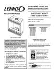
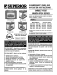
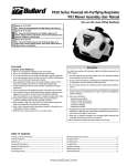
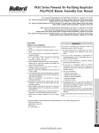
HOMEOWNER'S CARE AND
OPERATION INSTRUCTIONS
DIRECT VENT
SPECTRA SERIES
LENNOX HEARTH PRODUCTS
VENTED GAS FIREPLACE HEATERS - DIRECT VENT MODELS
P/N 875,020M REV. A 12/2002
MODELS
LSS-35CN
LSS-35CP
LSS-40 MODEL SHOWN
OTL Report No. 116-F-02-05
WARNING: IF THE INFORMATION IN THIS MANUAL
IS NOT FOLLOWED EXACTLY, A FIRE OR EXPLOSION MAY RESULT CAUSING PROPERTY DAMAGE, PERSONAL INJURY OR LOSS OF LIFE.
FOR YOUR SAFETY: Do not store or use gasoline
or other flammable vapors or liquids in the vicinity of this or any other appliance.
FOR YOUR SAFETY: What to do if you smell gas:
•
•
•
•
DO NOT light any appliance.
DO NOT touch any electrical switches.
DO NOT use any phone in your building.
Immediately call your gas supplier from a
neighbor’s phone.
Follow your gas suppliers instructions.
• If your gas supplier cannot be reached, call the
fire department.
LSS-40CN
LSS-40CP
RETAIN THESE INSTRUCTIONS
FOR FUTURE REFERENCE
AVERTISSEMENT: ASSUREZ-VOUS DE BIEN SUIVRE
LES INSTRUCTIONS DONNÉ DANS CETTE NOTICE POUR
RÉDUIRE AU MINIMUM LE RISQUE D'INCENDIE OU
POUR ÉVITER TOUT DOMMAGE MATÉRIEL, TOUTE
BLESSURE OU LA MORT.
POUR VOTRE SÉCURITÉ: Ne pas entreposer ni utiliser
d'essence ni d'autre vapeurs ou liquides inflammables
dans le voisinage de cet appareil ou de tout autre
appareil.
POUR VOTRE SÉCURITÉ: Que faire si vous sentez une
odeur de gaz:
• Ne pas tenter d'allumer d'appareil.
• Ne touchez à aucun interrupteur. Ne pas vous servir
des téléphones se trouvant dans le batiment où
vous vous trouvez.
• Evacuez la piéce, le bâtiment ou la zone.
• Appelez immédiatement votre fournisseur de gaz
depuis un voisin. Suivez les instructions du
fournisseur.
• Si vous ne pouvez rejoindre le fournisseur de gaz,
appelez le service dos incendies.
Installation and service must be performed by a
L'installation et service doit être exécuté par un qualifié
qualified installer, service agency or the gas
installeur, agence de service ou le fournisseur de gaz.
supplier.
NOTE: DIAGRAMS & ILLUSTRATIONS NOT TO SCALE.
1
CONGRATULATIONS!
GENERAL INFORMATION
In selecting this LENNOX Signature Series Direct-Vent Gas Appliance you have chosen
the finest and most dependable fireplace to be found anywhere. A beautiful, prestigious,
alternative to a wood burning fireplace. Welcome to a Family of tens of thousands of
satisfied LENNOX Fireplace Owners.
Note: Installation and repair should be performed by a qualified service person. The appliance should be inspected annually by a qualified professional service technician. More frequent inspections and cleanings may be required due to excessive lint from carpeting,
bedding material, etc. It is imperative that the
control compartment, burners and circulating
air passage ways of the appliance be kept clean.
Please read and carefully follow all of the instructions found in this manual. Please pay
special attention to the safety instructions provided in this manual. The Homeowner's
Care and Operation Instructions included here will assure that you have many years of
dependable and enjoyable service from your LENNOX product.
TABLE OF CONTENTS
Introduction ..................................... page
2
General Information ......................... page
2
Operation/Care of Your Appliance .... page
3
RF Comfort Control Valve Operation page
3
Transmitter Operation ...................... page
4
Trouble shooting ............................. page
5
Glass Cleaning ................................. page
6
Maintenance .................................... page
6
Maintenance Schedule ..................... page
7
Front Glass Enclosure Panel,
Removal and Installation ............... page
8
Burner Adjustments ......................... page
8
Flame Appearance and Sooting ....... page
8
Adjustment ...................................... page
9
Vent Restrictor ................................ page
9
Log Placement ................................. page 10
Rockwool Placement ....................... page 11
Pilot Inspection ............................... page 11
Warranty .......................................... page 11
Replacement Parts .......................... page 11
These appliances feature a comfort control
valve which allows remote control of temperature, fan and flame appearance. These
appliances also use a spark ignitor (piezo)
that allows the appliance's pilot gas to be lit
without the use of matches. This system
provides continued service in the event of a
power outage.
The external electrical power (120v) is required to operate the provided circulating
blower.
These appliances comply with National Safety
Standards and are tested and listed by OmniTest Laboratories (Report No. 116-F-02-5) to
ANSI Z21.88-2002 (in Canada, CSA-2.33-2002),
and CAN/CGA-2.17-M91 in both USA and
Canada, as vented gas fireplace heaters.
The Installation must conform to local codes
or, in the absence of local codes, with the
National Fuel Gas Code, ANSI Z223.1/NFPA
54, or the Natural Gas and Propane Installation Code, CSA B149.1. The appliance, when
installed, must be electrically grounded in
accordance with local codes or, in the absence of local codes, with the National Electrical Code, ANSI/NFPA 70, or the Canadian
Electrical Code, CSA C22.1.
Product Reference Information ....... page 11
Accessory Components ................... page 12
Replacement Parts List ..................... page 14
INTRODUCTION
The Fireplace models covered in this manual
are Direct-Vent sealed combustion vented gas
fireplace heaters designed for residential application. Direct-Vent appliances operate with
the combustion chamber completely isolated
from the inside atmosphere. All air for combustion is brought in from the outside and
exhaust gases are vented through the same
direct vent, vent system.
2
DO NOT ATTEMPT TO ALTER OR MODIFY
THE CONSTRUCTION OF THE APPLIANCE OR ITS
COMPONENTS. ANY MODIFICATION OR ALTERATION MAY VOID THE WARRANTY,
CERTIFICATION AND LISTINGS OF THIS UNIT.
WARNING: IMPROPER INSTALLATION,
ADJUSTMENT, ALTERATION, SERVICE
OR MAINTENANCE CAN CAUSE INJURY
OR PROPERTY DAMAGE. REFER TO
THIS MANUAL. FOR ASSISTANCE OR
ADDITIONAL INFORMATION CONSULT
A QUALIFIED INSTALLER, SERVICE
AGENCY OR THE GAS SUPPLIER.
NOTE: DIAGRAMS & ILLUSTRATIONS NOT TO SCALE.
S'assurer que le brùleur et le compartiment
des commandes sont propres. Voir les instructions d'installation et d'utilisation qui
accompagnent l'appareil.
Provide adequate clearances around air openings and adequate accessibility clearance for
service and proper operation. Never obstruct
the front openings of the appliance.
Due to high temperatures the appliance should
be located out of traffic and away from furniture and draperies. Locate furniture and window coverings accordingly.
WARNING: THESE FIREPLACES ARE
VENTED HEATERS. DO NOT BURN
WOOD OR OTHER MATERIAL IN THESE
APPLIANCES.
These appliances are designed to operate on
natural or propane gas only.
Input of millivolt models is variable. These
rates are shown in the following table:
Model
Fuel
Maximum
Input
(BTU/H)
Minimum
Input
(BTU/H)
LSS-35CN
Nat. Gas
33,000
23,500
LSS-35CP
LP Gas
31,000
23,500
LSS-40CN
Nat. Gas
41,500
28,400
LSS-40CP
LP Gas
39,000
30,700
The following table shows the units' orifice size
for the elevations of 0-4500 feet (0-1370 meters).
Model
Fuel
Rear
Burner
Front
Burner
LSS-35CN
Nat. Gas
#44
#50
LSS-35CP
LP Gas
#55
#61
LSS-40CN
Nat. Gas
#42
#45
LSS-40CP
LP Gas
0.054"
#56
Maximum manifold pressure is 3.5 in. w.c.
(0.87 kPa) for natural gas and 10 in. w.c.
(2.49 kPa) for LP/Propane gas.
Do not use these appliances if any part has been
under water. Immediately call a qualified, professional service technician to inspect the appliance
and to replace any parts of the control system and
any gas control which have been under water.
Ne pas se servir de cet appareil s'il a été plongé
dans l'eau, complètement ou en partie. Appeler
un technicien qualifié pour inspecter l'appareil et
remplacer toute partie du système de contrôle et
toute commande qui ont été plongés dans l'leau.
Test gage connections are provided on the
front of the millivolt gas control valve (identified OUT for the manifold side and IN for inlet
pressure.
Minimum inlet gas pressure to these appliances is 5.0 inches water column (1.24 kPa) for
natural gas and 11 inches water column (2.74
kPa) for propane for the purpose of input adjustment.
Maximum inlet gas supply pressure to these
appliances is 10.5 inches water column (2.61
kPa) for natural gas and 13.0 inches water
column (3.23 kPa) for propane.
The appliance must be isolated from the gas
supply piping system (by closing its individual
manual shut-off valve) during any pressure testing of the gas supply piping system at test
pressures equal to or less than ¹⁄₂ psig (3.5 kPa).
The appliance and its individual shut-off valve
must be disconnected from the gas supply
piping system during any pressure testing of
that system at pressures in excess of ¹⁄₂ psig
(3.5 kPa).
These appliances must not be connected to a
chimney or flue serving a separate solid fuel
burning appliance.
Any safety guard or screen removed for servicing the appliance must be replaced prior
to operating the appliance.
WARNING: FAILURE TO COMPLY
WITH THE INSTALLATION AND OPERATING INSTRUCTIONS PROVIDED
IN THIS DOCUMENT WILL RESULT IN
AN IMPROPERLY INSTALLED AND OPERATING APPLIANCE, VOIDING ITS
WARRANTY. ANY CHANGE TO THIS
APPLIANCE AND/OR ITS OPERATING
CONTROLS IS DANGEROUS. IMPROPER INSTALLATION OR USE OF
THIS APPLIANCE CAN CAUSE SERIOUS INJURY OR DEATH FROM FIRE,
BURNS, EXPLOSION OR CARBON
MONOXIDE POISONING.
Carbon Monoxide Poisoning: Early signs of
carbon monoxide poisoning are similar to the
flu with headaches, dizziness and/or nausea.
If you have these signs, obtain fresh air immediately. Turn off the gas supply to the appliance and have it serviced by a qualified professional, as it may not be operating correctly.
WARNING: CHILDREN AND ADULTS
SHOULD BE ALERTED TO THE HAZARDS
OF HIGH SURFACE TEMPERATURES. USE
CAUTION AROUND THE APPLIANCE TO
AVOID BURNS OR CLOTHING IGNITION.
YOUNG CHILDREN SHOULD BE CAREFULLY SUPERVISED WHEN THEY ARE IN
THE SAME ROOM AS THE APPLIANCE.
WARNING: DO NOT PLACE CLOTHING OR OTHER FLAMMABLE MATERIALS ON OR NEAR THIS APPLIANCE.
AVERTISSEMENT: SURVEILLER LES
ENFANTS. GARDER LES VÊTEMENTS,
LES MEUBLES, L'ESSENCE OU AUTRES
LIQUIDES À VAPEUR INFLAMMABLES
LOIN DE L'APPAREIL.
OPERATION AND CARE OF YOUR
APPLIANCE
For piezo ignitor location, refer to Figure 1.
The control compartment is located behind
the bottom front face piece. For access:
In the Cast Iron Face accessory - simply lift up
and pull directly out.
Honeywell
Gas Valve
Piezo
Ignitor
Honeywell RF Control Millivolt Gas Valve
Showing Piezo Ignitor Location
Figure 1
INSTRUCTIONS FOR RF COMFORT
CONTROL VALVE
The Comfort Control Valve allows remote control of temperature, fan and flame appearance.
Note: The antenna should hang in free air and
away from any grounded metal.
Operation (refer to Figure 2, page 4 )
Step 1. If the manual switch is in the remote
position, switch it to LOCAL.
Step 2. Turn the Pilotstat knob counterclockwise from OFF to the PILOT position,
push the knob down and hold it in position.
The pilot valve will open and allow gas to flow
to the pilot burner.
Step 3. Actuate the plunger on the piezo
(several times if necessary) until the pilot
burner is lit. When the pilot burner is lit, the
LED on the control will come on after approximately 40 seconds. The receiver/valve is fully
powered.
Step 4. Release the knob. The shaft will
move forward. The pilot burner should now
stay burning. If the pilot burner goes out,
repeat Steps 2 and 3.
Step 5. Turn the knob counterclockwise to
the ON position. If the manual switch is in the
LOCAL position, the main burner will turn on
immediately.
In the Rectangular or Arched Face accessory Pivot the main face door (bottom) on the two
hinge pins, and drop down to open.
NOTE: DIAGRAMS & ILLUSTRATIONS NOT TO SCALE.
3
Step 6. ON the initial use of a transmitter, a
recognition operation is required between the
receiver/valve and transmitter. Change the switch
from LOCAL to REMOTE. Press the fan or flame
button on the transmitter within 30 seconds.
The LED will blink indicating the transmitter will
now work with the receiver/valve. If the switch
continues in the REMOTE position, the transmitter will now control the main valve, flame modulation level and fan control.
Screw Cap Of Pilot
Adjustment
Step 7. If the manual switch is in the LOCAL
position, the valve will be at the highest fixed
pressure setting. The transmitter will control
the fan only.
Shut Off Procedure
Local/Remote
Switch
Pilotstat
Knob
Display
- Room Temperature
- Set Temperature
- Flame Height Level
- Fan Speed Level
- Countdown Timer
- Low Battery
To shut off the system, turn the pilotstat knob
clockwise to the OFF position. This action closes
the main gas and safety valves. The transmitter
now cannot turn on the main burner or fan.
Mode
- Auto
- On
- Off
TRANSMITTER OPERATION (refer to Figure 3 )
Countdown
Timer
Off Mode
On (Manual) Mode
In the ON mode, the room temperature, flame
and fan levels will be shown. MANUAL will
appear next to both the flame and fan icons.
When the control is in the ON mode, the flame
and fan levels, and the delay timer are changed
with the up and down buttons. To change the
flame level, press the flame button followed by
an arrow key. To change the fan level, press the
fan key followed by an arrow key. Pushing the
arrow key once will change the level by one unit.
Delay Timer Mode
The shut off delay timer has a maximum of 2
(two) hours and a minimum of 0 (zero) minutes. To change the timer level, press the time
key followed by an arrow key. Pushing the key
once will change the timer by 10 (ten) minutes.
4
Antenna
LED
Figure 2
If the manual switch is in the REMOTE position, the transmitter can shut off the main
burner and fan. However, the control is still on
and a command from the transmitter can turn
on the main burner or fan.
In the OFF mode, the fireplace flame and fan
are off, the display will show OFF and displays
the room temperature. If the receiver is in
REMOTE mode, the fireplace will shut off.
Piezo Ignitor
Fan
Flame
Up
(Increases Flame
Height, Fan Speed
Timer, or Set Point)
Down
(Decreases Flame,
Fan Speed Timer,
or Set Point)
Figure 3
Auto Mode
Fan Override During Auto Mode
In the AUTO mode, the room temperature, set
temperature, flame and fan levels will be shown.
AUTO will appear next to both the flame and
fan icons.
If a lower or higher fan speed is desired when
operating in the AUTO mode, the fan speed can
be overridden by pushing the fan button followed by the up or down key.
When the control is in the AUTO mode, the
main burner will turn on/off or modulate based
on the heat needed to maintain the set temperature. The flame level will change automatically
to optimize the heat output needed to maintain
the set temperature. To change the set temperature, press the up or down key. Pushing a
key once will change the temperature by 1
(one) degree. The setting temperature range
from 40° F (4.5° C) to 90° F (32.0° C).
Pushing a key once will change the fan level by
one unit. In this mode "AUTO" is displayed next
to the flame icon and "MANUAL" is displayed
next to the fan icon.
In the AUTO mode, the fan speed will increase
with increasing flame height or decrease with
decreasing flame height. "AUTO" is displayed
next to the flame and fan icons.
Disable Thermostat Function
NOTE: DIAGRAMS & ILLUSTRATIONS NOT TO SCALE.
Change Between F/C Temperature Units
Push the up and down arrow keys simultaneously for at least 3 seconds to toggle between Fahrenheit and Celsius units.
To disable the thermostat function in the AUTO
mode, push the time and down key simultaneously for at least 3 seconds.
To Change Batteries
If an Error Code 3 is observed while performing the testing, complete the following:
1. Remove cover on the backside of the transmitter. Install 3 AAA batteries as shown inside
the cover and reattach the cover.
2. Once steps 1 thru 3 in OPERATION are
completed, receiver/valve and transmitter are
now ready. Press any button on transmitter
for recognition precess to occur between the
receiver/valve and transmitter.
3. Use functions as described in TRANSMITTER section.
Troubleshooting
Step 1. Make sure the spade connectors are
pushed all the way on. If the Error Code 3 is
still showing, then go to the next step.
Step 2. Switch the front two thermopile leads
with the back two. Be sure the lead is connected to the spade with the white dot next to
it (see Figure 4 ). If the Error Code 3 is still
showing, replace the thermopiles.
If an Error Code 8 is observed while performing the testing, complete the following:
Step 1. Confirm that the valve is not in
REMOTE mode.
Step 1. Locate LED light on valve.
Step 2. LED will blink after every valid command
received by the transmitter; this is not an error.
Step 3. Failure codes may occur anytime after
pilot burner is lit.
Step 4. Sequence is failure code followed by
light not blinking for 4 seconds.
Step 5. In the event of multiple failure codes,
next failure code follows previous failure code
by approximately 3 seconds
• If the valve is producing Error Code 8 and in
REMOTE mode, the valve is defective and
should be replaced.
LED Failure Code
(Number Of Blinks)
Service Action
8
Replace valve
7
Confirm stepper motor
connection exists
5
Confirm fan connection
exists and works
4
Confirm gas type; jumper
in place
3
Replace thermopiles
2
Turn fan ON
1
No action required
NOTE: Some keys are not active. This is
normal.
• If the valve is in LOCAL mode and producing
Error Code 8, then go to the next step.
Step 2. Slide the Remote/Local switch to
REMOTE and reprogram valve recognition (refer to in Operation section). The Error Code
will clear itself after approximately 1 1/2 minutes and return to normal operation.
COMFORT VALVE WIRING DIAGRAM
AUTO PATH DIAGRAM
CAUTION: LABEL ALL WIRES PRIOR TO
DISCONNECTION WHEN SERVICING CONTROLS.
WIRING ERRORS CAN CAUSE IMPROPER AND
DANGEROUS OPERATION. VERIFY PROPER
OPERATION AFTER SERVICING.
BLOWER
BLACK
F
M BLACK
WHITE
GREEN
GREEN
F
M
WHITE
F
F
White
Dots
VALVE
RED
WHITE
RED
Figure 4
WHITE
NOTE: DIAGRAMS & ILLUSTRATIONS NOT TO SCALE.
Figure 5
5
Glass Cleaning
Comfort Valve System Control Sequence Of Operation With Transmitter
It will be necessary to clean the glass periodically. During start-up it is normal for condensation to form on the inside of the glass. This
can cause lint, dust and other airborne particles to cling to the glass surface. Also initial
paint curing may deposit a slight film on the
glass. It is therefore recommended that the
glass be cleaned two or three times with a nonammonia household cleaner and warm water
(a gas fireplace glass cleaner is recommended).
After that the glass should be cleaned two or
three times during each heating season, depending on the circumstances present.
Note: Clean glass after first two weeks of
operation at least once. In some environments,
it may be necessary to clean the glass several
times during the first weeks of operation.
WARNING: DO NOT USE ABRASIVE
CLEANERS. NEVER CLEAN THE GLASS
WHEN IT IS HOT.
CAUTION: DO NOT ATTEMPT TO TOUCH THE
FRONT ENCLOSURE GLASS WITH YOUR
HANDS WHILE THE FIREPLACE IS IN USE.
Maintenance
The appliance and venting system should be
thoroughly inspected before initial use and at
least annually by a qualified service technician. However, more frequent periodic inspections and cleanings should be performed by
the homeowner. Homeowner must contact a
qualified service technician at once if any
abnormal condition is observed.
Refer to the maintenance schedule for maintenance tasks, procedures, periodicity and by whom
they should be performed. Always verify proper
operation of the appliance after servicing.
Figure 6
IMPORTANT: TURN OFF GAS AND ANY
ELECTRICAL POWER BEFORE SERVICING
THE APPLIANCE.
6
NOTE: DIAGRAMS & ILLUSTRATIONS NOT TO SCALE.
Maintenance Schedule
Annually (Before the onset of the Burning Season)
Maintenance Task
Accomplishing Person
Procedure
Inspecting/Cleaning Burner, Logs
and Controls
Qualified Service Technician
Inspect valve and ensure it is properly operating.
Check piping for leaks. Vacuum the control
compartment, fireplace logs and burner area.
Check Flame Patterns and Flame Height
Qualified Service Technician
Refer to Figure 9 (LSS-35),or Figure 10
(LSS-40) on page 10 and verify the flame
pattern and height displayed by the appliance conforms to the picture. Flames must
not impinge on the logs.
Inspecting/Cleaning Pilot and Burner
Qualified Service Technician
Refer to Figure 11 on page 11. Remove any
surface build-up on pilot and burner assembly. Wipe the pilot nozzles, ignitor/flame rod
and hood. Ensure the pilot flame engulfs the
flame sensor as shown.
Checking Vent System
Qualified Service Technician
Inspect the vent system at the top and at the
base (within the firebox) for signs of blockage
or obstruction. Look for any signs of dislocation of the vent components. Do not adjust
the vent restrictor adjustment rod.
Appliance Checkout
Qualified Service Technician
Perform the appropriate appliance checkout
procedure detailed in this manual.
Replacing Rockwool Ember Materials
Homeowner/Qualified Services Technician
Remove old ember materials. Place new
rockwool as described in this document.
Accomplishing Person
Procedure
Periodically (After the Burning Season)
Maintenance Task
Check Flame Patterns and Flame Height
Homeowner
Refer to Figure 9 (LSS-35), or Figure 10
(LSS-40) on page 10 and verify the flame
pattern and height displayed by the appliance
conforms to the picture. Flames must not
impinge on the logs.
Checking Vent System
Homeowner
Inspect the vent system at the top and at the
base (within the firebox) for signs of blockage or obstruction. Look for any signs of
dislocation of the vent components.
Cleaning Front Glass Enclosure Panel
Homeowner
Clean as necessary following the directions
provided in this manual. DO NOT TOUCH OR
ATTEMPT TO CLEAN GLASS WHILE HOT.
NOTE: DIAGRAMS & ILLUSTRATIONS NOT TO SCALE.
7
Front Glass Enclosure Panel, Removal
and Installation.
Refer to Figure 7 and remove the front glass
enclosure panel as follows:
WARNING: NEVER OPERATE THE APPLIANCE WITHOUT THE GLASS ENCLOSURE PANEL IN PLACE AND SECURE.
DO NOT OPERATE APPLIANCE WITH THE
FRONT GLASS PANEL CRACKED, BROKEN OR MISSING. REPLACEMENT PANELS ARE AVAILABLE THROUGH YOUR
LOCAL LENNOX DEALER AND MUST BE
INSTALLED BY A LICENSED OR QUALIFIED SERVICE TECHNICIAN.
1. Remove the cast iron, arched or rectangular
face kit.
2. Lift the bottom piece up and pull directly
out.
Burner Adjustments
These are direct-vent appliances. They are
designed to operate only with the front glass
enclosure panel properly installed. Generally, the glass enclosure panel should not be
removed except to gain access to the components within the firebox, and the appliance may only be operated without the front
glass enclosure panel in place for very brief
periods of time during initial appliance checkout and adjustment.
3. Lift the side pieces up and pull directly out.
The following paragraphs address burner adjustment concerns and procedures.
During this appliance checkout and adjustment period, a potential safety hazard exists
- EXERCISE EXTREME CAUTION to prevent
the occurrence of any burn injuries from the
exposed flames or hot surfaces. Also note,
that while the front glass enclosure panel is
removed, the flame appearance will appear to
be smaller than normal.
3. Swing the bottom of the door out and raise
it slightly to lift the top flange of the door frame
away from the appliance.
WARNING: HANDLE THE GLASS WITH
EXTREME CARE! TEMPERED GLASS IS
SUSCEPTIBLE TO DAMAGE (SCRATCHES,
FOR EXAMPLE) – HANDLE GLASS DOOR
(GLASS ENCLOSURE PANEL) GENTLY
WHILE REINSTALLING IT.
WARNING: NO NOT ATTEMPT TO SUBSTITUTE THE MATERIALS USED ON THIS
DOOR, OR REPLACE CRACKED OR BROKEN GLASS WITH ANY MATERIALS
OTHER THAN THOSE PROVIDED BY THE
APPLIANCE MANUFACTURER.
WARNING: DO NOT OPERATE APPLIANCE WITH THE GLASS FRONT REMOVED, CRACKED OR BROKEN. REPLACEMENT OF THE GLASS SHOULD
BE DONE BY A LICENSED OR QUALIFIED SERVICE PERSON.
8
CAUTION: DO NOT ATTEMPT TO REMOVE
UNTIL THE FACEPLATE IS COOL.
A) Cast Iron Face Kit:
1. Lift the top arched piece up and pull directly
out.
B) Arched or Rectangular Face Kit:
1. Lift the face assembly up and pull directly
out.
2. Locate the two (2) latches at the top of the
control compartment and disengage them from
the door frame's bottom Vee-flange, pulling
down on their handles to open them.
Top Flange
Door Frame
Vent Restrictor
Adjustment Rod
Glass Door
Latch
2. Position the door frame in front of the
firebox opening and engage the top flange
over the lip at the top of the firebox opening.
3. Swing the door down and back. Ensure the
gasket seats evenly as the door draws shut.
Engage the Vee-flange at the bottom of the
door with the latches and close the latches to
secure the door.
4. Hook the cast iron, arched or rectangular
facade onto the face of the fireplace.
Flame Appearance and Sooting
Proper flame appearance is a matter of taste.
Generally most people prefer the warm glow of
a yellow to orange flame. Appliances operated
with air shutter openings that are too large will
exhibit flames that are blue and transparent.
These weak, blue and transparent flames are
termed anemic. If the air shutter opening is too
small sooting may develop.
Sooting is indicated by black puffs developing
at the tips of very long orange flames. Sooting
results in black deposits forming on the logs,
appliance inside surfaces and on exterior surfaces adjacent to the vent termination. Sooting
is caused by incomplete combustion in the
flames and a lack of combustion air entering the
air shutter opening.
To achieve a warm yellow to orange flame with
an orange body that does not soot, the shutter
opening must be adjusted between these two
extremes. No smoke or soot should be present.
Reposition the logs if the flames impinge on
any of them.
Bottom Vee-flange
Door Frame
Latch
Firebox Floor
Figure 7
If the logs are properly positioned and sooting
conditions exist, the air shutter opening on the
main burner tube should be adjusted. Normally,
the more offsets in the vent system, the greater
the need for the air shutter to be opened further.
To install the front glass enclosure panel,
proceed as follows:
WARNING: AIR SHUTTER ADJUSTMENT
SHOULD ONLY BE PERFORMED BY A
QUALIFIED PROFESSIONAL SERVICE
TECHNICIAN.
1. Retrieve the glass door frame. Visually
inspect the gasket on the backside of the
panel. The gasket surface must be clean, free
of irregularities and seated firmly.
ENSURE THAT THE FRONT GLASS PANEL IS IN
PLACE AND SEALED DURING ADJUSTMENT.
NOTE: DIAGRAMS & ILLUSTRATIONS NOT TO SCALE.
Adjustment
Vent Restrictor
Burner
Venturi
Tube
CAUTION: THE AIR SHUTTER ADJUSTMENT
ROD (SEE FIGURE 8 ) AND NEARBY APPLIANCE SURFACES ARE HOT. EXERCISE CAUTION TO AVOID INJURY WHILE ADJUSTING
FLAME APPEARANCE.
To adjust the flame, restate the air shutter
adjustment rod toward the back or toward the
front of the fireplace (rod located in the lower
control area). Position the air shutter to the
factory setting as shown in the Table of Figure
8. Allow the burner to operate for at least 15
minutes. Observe the flame continuously. If it
appears weak or sooty as previously described,
adjust the air shutter by pushing or pulling on
the adjustment rod until the flame appearance
is as desired.
Air Shutter
Opening
Air
Shutter
Door
Orifice
Air Shutter
Adjusting
Rod
The air shutter adjustment rod and associated
adjustable air shutter is patented technology.
Flame adjustments can be made quickly and
accurately to taste without the need of disassembling the appliance and waiting for 30 minutes after each adjustment.
Propane models may exhibit a flame pattern
that may candle or appear stringy. If this is
problematic or persists as the appliance is
continually operated, adjust the air shutter
closed as described in the previous paragraphs.
Operate the appliance for a period of time as
the effect diminishes, ensuring that the appliance does not develop sooty flames.
The appliance has a built-in vent restrictor,
refer to Figure 7, page 8 for location, to adjust
the flow of exhaust gases. This ensures
proper combustion for all vent configurations. Depending on the vent configuration,
you may be required to adjust the restriction
position. See below for guidelines.
CAUTION: THE FIREPLACE NEEDS TO BE ON
DURING THE ADJUSTMENT OF THE VENT
RESTRICTOR. USE A GLOVE TO PROTECT
YOUR HAND FROM BURNS.
Venting
Configuration
Adjustment Rod
Position
1. Horizontal Venting
with 6" vent section and
one 90° elbow.
* Pointed toward
2. Vertical venting.
Models
LSS-35
LSS-40
Gas
Type
FACTORY AIR
SHUTTER SETTING
OPENING
inches (mm)
Nat.
Prop.
Nat.
Prop.
1/2 (13.0)
5/8 (15.8)
1/2 (13.0)
5/8 (15.8)
3. Combination of vertical and horizontal
venting.
the front.
* Pointed toward
the left.
* Adjust
accordingly for
best result.
* Adjustment to the air shutter may be required to get the desired flame appearance,
(refer to Figure 8 ).
Figure 8
When satisfied that the appliance operates
properly, proceed to finish the installation.
Leave the control knob in “ON” position and
turn the remote switch “OFF.” Close the lower
control compartment door.
NOTE: DIAGRAMS & ILLUSTRATIONS NOT TO SCALE.
9
Log Placement
WARNING: LOGS GET VERY HOT AND
WILL REMAIN HOT UP TO ONE HOUR
AFTER GAS SUPPLY IS TURNED OFF.
HANDLE ONLY WHEN LOGS ARE COOL.
TURN OFF ALL ELECTRICITY TO THE
APPLIANCE BEFORE YOU INSTALL
GRATE AND LOGS.
WARNING: THE SIZE AND POSITION ON
THE LOG SET WAS ENGINEERED TO GIVE
YOUR APPLIANCE A SAFE, RELIABLE
AND ATTRACTIVE FLAME PATTERN.
ANY ATTEMPT TO USE A DIFFERENT
LOG SET IN THE FIREPLACE WILL VOID
THE WARRANTY AND WILL RESULT IN
INCOMPLETE COMBUSTION, SOOTING,
AND POOR FLAME QUALITY.
Figure 9
MODEL LSS-35
Figure 10
MODEL LSS-40
WARNING: THIS APPLIANCE IS NOT
MEANT TO BURN WOOD. ANY ATTEMPT TO DO SO COULD CAUSE IRREPARABLE DAMAGE TO YOUR APPLIANCE AND PROVE HAZARDOUS TO
YOUR SAFETY.
Carefully position the ceramic fiber logs over
the burner as shown in Figure 9 (LSS-35) or
Figure 10 (LSS-40). For more detailed placement instructions, refer to the LOG PLACEMENT GUIDE accompanying this document.
Proper log placement is critical to prevent
sooting. Logs should be placed in the gaps
between the flame peaks and should be positioned so that at no time they impinge the
flames.
10
NOTE: DIAGRAMS & ILLUSTRATIONS NOT TO SCALE.
Glowing Embers (Rockwool) Placement
Refer to the detailed glowing embers placement instructions provided in the LOG PLACEMENT GUIDE accompanying this document.
Honeywell RF Control Millivolt Appliance
Pilot Checkout
To adjust pilot burner; (by a qualified service
technician)
1. Remove pilot adjustment cap.
³⁄₈" Min
(9 mm)
2. Adjust pilot screw to provide properly sized
flame.
3. Replace pilot adjustment cap.
Pilot Inspection
To obtain proper operation, it is imperative that
the pilot and burner's flame characteristics are
steady, not lifting or floating (see Figure 11 ).
MILLIVOLT HONEYWELL
The primary air shutter is set at the factory and
should only be adjusted, if necessary, by a
qualified service technician.
Thermopile
Ignitor Rod
Hood
³⁄₈" Min
(9 mm)
Pilot
Nozzels
Thermopile
Figure 11
Typically, the top 3/8" of the thermopile should be
engulfed in the pilot flame (Figure 11 ).
WARRANTY
Your gas appliance is covered by a limited
twenty year warranty. You will find a copy of
the warranty accompanying this manual.
Please read the warranty to be familiar with
its coverage.
Retain this manual. File it with your other documents for future reference.
REPLACEMENT PARTS
A complete parts list is found at the end of this
manual. Use only parts supplied from the
manufacturer.
Normally, all parts should be ordered through
your Lennox distributor or dealer. Parts will be
shipped at prevailing prices at time of order.
When ordering repair parts, always give the
following information:
1. The model number of the appliance.
2. The serial number of the appliance.
3. The part number.
4. The description of the part.
5. The quantity required.
6. The installation date of the appliance.
If you encounter any problems or have any
questions concerning the installation or application of this system, please contact your distributor, or Lennox directly:
LHP
1110 West Taft Avenue
Orange, CA 92865
PRODUCT REFERENCE INFORMATION
We recommend that you record the following important information about your fireplace. Please
contact your Lennox dealer for any questions or concerns. For the number of your nearest Lennox
dealer, please call 800-731-8101
Your Fireplace's Model Number _______________________________________
Your Fireplace's Serial Number ________________________________________
The Date On Which Your Fireplace Was Installed __________________________
The Type of Gas Your Fireplace Uses ___________________________________
Your Dealer's Name _________________________________________________
NOTE: DIAGRAMS & ILLUSTRATIONS NOT TO SCALE.
11
ACCESSORY COMPONENTS
Cast Iron Kits
Model
Series
Catalog
No.
Model No.
LSS-35
H0378
LSS-CA35
LSS-40
H0398
LSS-CA40
Cast Iron Kits
These cast iron face kits are designed to be used in conjunction with the grillwork kits. Together,
when installed, these kits complete the front aspect of the Spectra LSS Series gas fireplaces. A
detailed set of instructions (P/N 750,150M) is included with each kit.
Touch-Up Paint (Black) Kit
90L73
FTPK-B
Touch-Up Paint Kit
Grillwork Kits (Top & Bottom)
Model
Series
Finish
Catalog No.
Model No.
LSS-35
Black
Gold
Nickel
H0379
H0380
H0381
LSS-GB35
LSS-GG35
LSS-GN35
LSS-40
Black
Gold
Nickel
H0399
H0400
H0404
LSS-GB40
LSS-GG40
LSS-GN40
Grillwork Kits (Top & Bottom)
These grillwork kits are designed to be used in conjunction with the Cast Iron Face kits.
Together, when installed, these complete the front aspect of the Spectra LSS Series gas
fireplace. A detailed set of instructions (P/N 750,151M) is included with each kit.
12
NOTE: DIAGRAMS & ILLUSTRATIONS NOT TO SCALE.
Repair of minor scratches and discoloration
of the appliance's painted surfaces may be
accomplished with the use of this touch-up
paint kit.
ACCESSORY COMPONENTS CONTINUED
Rectangular Face Kits
Model
Series
Finish
Catalog No.
Model No.
LSS-35
Black
Gold
Brushed Nickel
H0386
H0387
H0389
LSS-PT35B
LSS-PT35G
LSS-PT35BN
LSS-40
Black
Gold
Brushed Nickel
H0409
H0410
H0413
LSS-PT40B
LSS-PT40G
LSS-PT40BN
Rectangular Face Kits
These rectangular face kits are designed to be used with the Spectra LSS series gas fireplace.
When installed, these kits complete the front aspect of these fireplaces. A detailed set of
instructions (P/N 750,152M) is included with each kit.
Arched Face Kits
Model
Series
Finish
Catalog No.
Model No.
LSS-35
Black
Gold
Brushed Nickel
H0382
H0383
H0385
LSS-PA35B
LSS-PA35G
LSS-PA35BN
LSS-40
Black
Gold
Brushed Nickel
H0405
H0406
H0408
LSS-PA40B
LSS-PA40G
LSS-PA40BN
Arched Face Kits
These arched face kits are designed to be used with the Spectra LSS series gas fireplace.
When installed, these kits complete the front aspect of these fireplaces. A detailed set of
instructions (P/N 750,152M) is included with each kit.
NOTE: DIAGRAMS & ILLUSTRATIONS NOT TO SCALE.
13
REPLACEMENT PARTS LIST
No.
LSS-35
DESCRIPTION
LSS-40
Part No.
Qty.
Part No.
Qty.
1.
Enclosure, Glass Front (Complete)
LB-92534N
1
LB-92534P
1
2.
Latch
69L2101
2
69L2101
2
3.
Log Set (Complete)
35M6101
1
35M6201
1
4.
Burner Rear Assembly
35M7701
1
35M7801
1
5.
Burner Front
35M7501
1
35M7601
1
6.
Burner Bracket
LB-92813
2
LB-92813
2
7.
Burner Support - Left
LB-92811F
1
LB-92811G
1
8.
Burner Support - Right
LB-92811B
1
LB-92811C
1
9.
Front Baffle
LB-92812B
1
LB-92812C
1
10.
Grate Assembly
LB-92820B
1
LB-92820C
1
11.
Refactory Panels
41M86
1
41M87
1
12.
Orifice, Rear Main Burner - Nat. Gas
60J80
1
LB-69645
1
12.
Orifice, Rear Main Burner - LP Gas
19L52
1
88J59
1
13.
Orifice, Front Main Burner - Nat. Gas
35M9001
1
39L6601
1
13.
Orifice, Front Main Burner - LP Gas
35M9101
1
62L3701
1
14.
Bag of Rock Wool
15.
Venturi Tube - Rear Burner
16.
17.
88L53
1
88L53
1
35M3701
1
35M3801
1
Gas Line - Rear Burner
LB-92834A
1
LB-92834B
1
Gas Line - Front Burner
LB-92833A
1
LB-92833B
1
18.
Air Shutter Adjustment Linkage
LB-92544
1
LB-92544
1
19.
Linkage Mounting Bracket
LB-92546
1
LB-92546
1
20.
Pilot Bracket
LB-92770
1
LB-92770
1
21.
RF Remote Control
35M53
1
35M53
1
22.
Power Cord
35M8501
1
35M8501
1
23.
Blower
35M8401
1
35M8401
1
Part No.
Qty.
Part No.
Qty.
GAS CONTROLS
14
LSS-35
LSS-40
No.
DESCRIPTION
30.
Gas Valve - Natural Gas
35M5401
1
35M5401
1
30.
Gas Valve - LP Gas
35M8301
1
35M8301
1
31.
Pilot Assembly
35M5201
1
35M5201
1
32.
Pilot Generator
60J79
2
60J79
2
33.
Pilot Tube
67L6801
1
67L6801
1
34.
Electrode and Cable
67L8701
1
67L8701
1
35.
Flexible Connector
43K33
1
43K33
1
36.
Piezo Ignitor
24M8901
1
24M8901
1
NOTE: DIAGRAMS & ILLUSTRATIONS NOT TO SCALE.
REPLACEMENT PARTS
11
LSS35
3
LSS40
1
12
13
32
2
31
14
33
19
18
20
34
35
36
30
4
6
10
15
7
9
6
17
5
8
16
21
22
Gas Train Assembly - Bottom View
NOTE: DIAGRAMS & ILLUSTRATIONS NOT TO SCALE.
23
15
LENNOX reserves the right to make changes at any time, without notice, in design, materials, specifications, prices and also to discontinue colors, styles and products.
Consult your local distributor for fireplace code information.
Printed in U.S.A. © 2002 by LENNOX
16
P/N 875,020M REV. A 12/2002
NOTE: DIAGRAMS & ILLUSTRATIONS NOT TO SCALE.
1110 West Taft Avenue • Orange, CA 92865