1
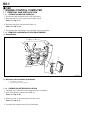
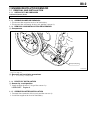
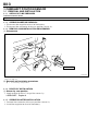
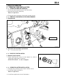
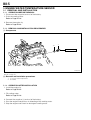
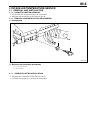
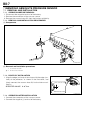
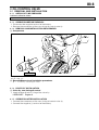
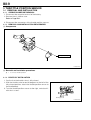
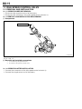
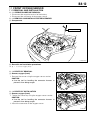
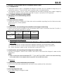
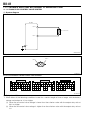
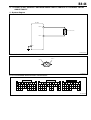
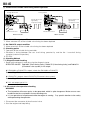
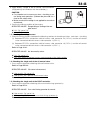
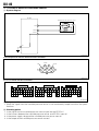
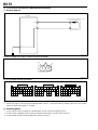
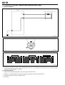
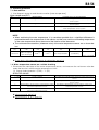
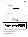
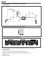
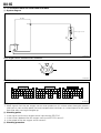
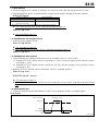
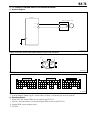
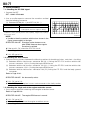
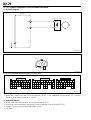
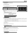
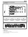
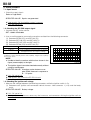
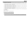
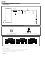
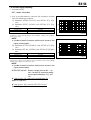
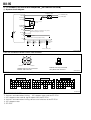
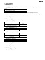
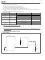
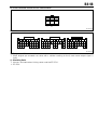
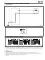
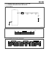
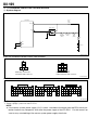
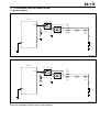
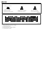
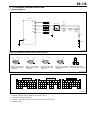
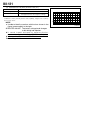
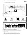
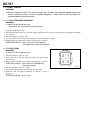
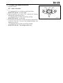
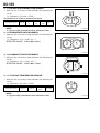
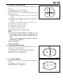
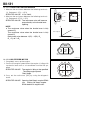
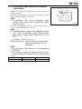
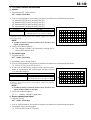
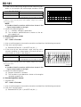
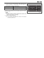
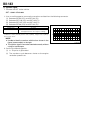
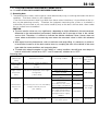
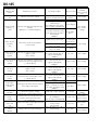
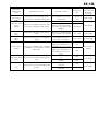
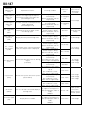
B8-116 9. Checking the EFI ECU output signal (2) 1. Connect the SST. SST: 09842-97209-000 2. Measure the voltage between terminals SST50 (FC1) and SST130 (E1)under the following condition. 3. Under the following conditions, measure the voltage between the SST47 (FC3) and SST130 (E1) terminals. (Immobilizer equipped vehicles) SPECIFIED VALUE: Condition 2 seconds after the ignition switch is set to "ON" When 2 seconds or more have elapsed after the ignition switch is set to "ON" When idling Specified value 2.0 V or lower Battery voltage 2.0 V or lower If it is OK, go to 10. If the result is NG, check the EFI ECU circuit. Refer to Page A1-32. 10.Wire harness check (2) 1. Check the wiring harness between the following sections for breaking of wires, and shortcircuiting. (1) Between vehicle side harness connector 50 (FC1) linking the EFI ECU and connector 3 on the fuse block connecting fuel pump relay. (2) Between EFI ECU vehicle harness connector 47 (FC3) and fuel pump relay fuse block connector 3 (immobilizer equipped vehicles) SPECIFIED VALUE: No abnormality exists. If the result is OK, check the EFI ECU circuit. Refer to Page A1-32. If it is NG, repair or replace harness and connector at the faulty section. 11.Wire harness check (3) 1. Check the wiring harness between the following sections for breaking of wires, and shortcircuiting. (1) Between connector 2 (switch side) linking the fuse box connecting the fuel pump relay and connector 4 the fuse box connecting the main relay. SPECIFIED VALUE: No abnormality exists. If it is OK, go to 12. Refer to Page A1-32. If it is NG, repair or replace harness and connector at the faulty section.