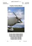
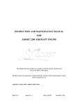
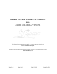
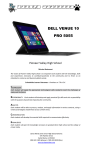
1
Jabiru Aircraft Pty Ptd
Aircraft Service Manual
11.4
Jabiru J160 / J170 Variants
FUEL SHUT-OFF VALVE
See Figure 46 or 47, depending on model variant.
11.4.1
DESCRIPTION
The fuel shut-off valve is a two-position ON – OFF valve which is located in front of the
main longitudinal beam.
11.4.2
FUEL VALVE REMOVAL & INSTALLATION
1.
Turn OFF both taps between wing tanks and header tank. Cover both tank cap
vents.
2.
Remove fuel shut-off valve cover.
3.
Remove shut-off valve handle.
4.
Remove cover plate.
5.
Disconnect and cap fuel lines at shut-off valve.
6.
Remove shut-off valve.
7.
Reverse the preceding steps for installation.
WARNING
Fuel valves between wing tanks and header tanks must be in the “ON” position
during flight. CS-VLA variants must have these taps wired “ON” using electrical
fuse wire.
Ensure wing tank cap vent covers are removed.
11.5
FUEL FILTERS
11.5.1
CS-VLA FILTER DESCRIPTION
The fuel filter is of the in-line type and is located inside the header tank enclosure behind
the seats.
11.5.2
NON CS-VLA MODEL VARIANT FILTER DESCRIPTION
The fuel filter is of the in-line type and is located just inside the cabin above the rudder
pedals.
11.5.3
CS-VLA MODEL FUEL FILTER REMOVAL & INSTALLATION
1.
Turn fuel valves between wing tanks and header tank to OFF. Cover wing tank cap
vents.
2.
Try to kink to main fuel line above the fuel filter being careful not to damage.
3.
Place a cloth beneath the filter to collect any fuel which may be split during removal
of the filter.
REVISION
0
Dated : July 2005
L:\files\Technical_manuals\J160_J170\J160_&_J170_working_ files\J160_&_J170_Tech.doc
Print Date: 15/08/2005 10:25:00 AM
Issued By: RAS
Page: 121 of 156
Jabiru Aircraft Pty Ptd
Aircraft Service Manual
Jabiru J160 / J170 Variants
4.
Disconnect the fuel lines at both ends of the filter.
5.
Remove filter.
6.
Reverse the preceding steps for installation. Ensure waste cloth is removed.
WARNING
Fuel valves between wing tanks and header tanks must be wired in the “ON”
position using electrical fuse wire during flight.
Ensure wing tank cap vent covers are removed.
The fuel filter must only be installed in one direction. An arrow on the side of the
filter marks the fuel flow direction. Ensure this arrow is pointed towards the
Firewall and Engine.
11.5.4
NON CS-VLA MODEL FUEL FILTER REMOVAL & INSTALLATION
7.
Turn main fuel valve on the cabin main beam OFF.
8.
Place a cloth beneath the filter to collect any fuel which may be split during removal
of the filter.
9.
Disconnect the fuel lines at both ends of the filter.
10.
Remove filter.
11.
Reverse the preceding steps for installation. Ensure waste cloth is removed.
WARNING
The fuel filter must only be installed in one direction. An arrow on the side of the
filter marks the fuel flow direction. Ensure this arrow is pointed towards the
Firewall and Engine.
11.6
FUEL PUMPS
11.6.1
PRIMARY PUMP
The Primary Fuel Pump is located on the Starboard rear of the Engine. Refer to engine
Maintenance & Instruction Manual for details.
11.6.2
CS-VLA SECONDARY PUMP
A secondary, electronic pump is mounted inside the header tank enclosure behind the
seats. This pump is a back-up to the Primary Pump. It is recommended that the
Secondary Pump be engaged at least during take-off and landing.
11.6.3
NON CS-VLA SECONDARY PUMP
A secondary, electronic pump is mounted inside the centre console above the rudder
pedals. This pump is a back-up to the Primary Pump. It is recommended that the
Secondary Pump be engaged at least during take-off and landing.
REVISION
0
Dated : July 2005
L:\files\Technical_manuals\J160_J170\J160_&_J170_working_ files\J160_&_J170_Tech.doc
Print Date: 15/08/2005 10:25:00 AM
Issued By: RAS
Page: 122 of 156
Jabiru Aircraft Pty Ptd
Aircraft Service Manual
Jabiru J160 / J170 Variants
12 SECTION 12 – INSTRUMENTS & INSTRUMENT
SYSTEMS
12.1
GENERAL
This Section describes the typical instrument installation and its operating system.
Emphasis is placed on trouble shooting and corrective measures only. It does NOT deal
with specific instrument repairs as this usually requires special equipment and data and
should be handled by instrument specialists. Malfunctioning instruments should be either
returned to JABIRU AIRCRAFT Pty Ltd or sent to an approved instrument overhaul and
repair station for servicing.
Our concern here is with preventive maintenance on the various instrument systems and
correction of system faults which will result in instrument malfunctions. The descriptive
material, maintenance and trouble shooting information in this Section is intended to help
the owner or mechanic determine malfunctions and correct them, up to the defective
instrument itself, at which point an instrument technician should be called in. Some
instruments, such as Oil Temperature and Pressure Gauges, are simple and relatively
inexpensive and repairs will usually cost more than a new instrument. Flight instruments,
on the other hand, are usually well worth repairing. The words “replace instrument” in the
text, therefore, should be taken only in the sense of physical replacement in the aircraft.
Whether replacement is to be with a new instrument, an exchange one, or an original
instrument is to be repaired must be decided on the basis of the individual circumstances.
12.2
INSTRUMENT PANEL
The instrument panel assembly consists of a stationary panel. The lower part of the panel
contains switches and circuit breakers which are not sensitive to vibration. The
instruments are screw-mounted to the panel.
12.2.1
INSTRUMENT PANEL REMOVAL & INSTALLATION
The panel is secured to the Firewall and for normal maintenance is not considered
removable. Access to instruments etc is gained by removing the panel facia containing the
instruments from the facia.
1.
Unscrew & remove the facia retaining screws from around the perimeter if the
panel.
2.
Remove the front facia. It is normally best to lie the facia on a cushion or similar
while working to reduce the risk of damaging the instruments or facia.
3.
Take care not to strain connections on wires or tubes.
4.
Assembly is the reverse of the above procedure.
12.2.2
INSTRUMENTS
Refer to Figure 44.
REVISION
0
Dated : July 2005
L:\files\Technical_manuals\J160_J170\J160_&_J170_working_ files\J160_&_J170_Tech.doc
Print Date: 15/08/2005 10:25:00 AM
Issued By: RAS
Page: 123 of 156
Jabiru Aircraft Pty Ptd
Aircraft Service Manual
Jabiru J160 / J170 Variants
Figure 44. Instrument Panel Layout – Basic Panel
REVISION
0
Dated : July 2005
L:\files\Technical_manuals\J160_J170\J160_&_J170_working_ files\J160_&_J170_Tech.doc
Print Date: 15/08/2005 10:25:00 AM
Issued By: RAS
Page: 124 of 156
Jabiru Aircraft Pty Ptd
Aircraft Service Manual
Jabiru J160 / J170 Variants
12.2.3
INSTRUMENT REMOVAL
Most instruments are secured to the panel with screws inserted through the panel face.
To remove an instrument, disconnect wiring or pluming to the instrument, remove
mounting screws and take instrument out from behind, or in some cases, from the front of
the panel.
In all cases when an instrument is removed, disconnected lines or wires should be
protected. Cap open lines and cover pressure connections on instrument to prevent
thread damage and entrance of foreign matter. Wire terminals should be insulated or tied
up so that accidental ground or short-circuiting will not occur.
12.2.4
INSTALLATION
Generally, the installation procedure is the reverse of the removal procedure. Ensure
mounting screws and nuts are tightened firmly, but do not over-tighten, particularly on
instruments having plastic cases. The same rule applies to connecting plumbing and
wiring.
12.3
PITOT & STATIC SYSTEMS
Refer to Figures 48 and 49.
The pitot system conveys ram air pressure to the airspeed indicator. The static system
vents vertical speed indicator (if fitted), altimeter and airspeed indicator to atmospheric
pressure through plastic tubing connected to a static port.
12.3.1
PITOT – STATIC SYSTEM MAINTENANCE
Proper maintenance of pitot and static system is essential for proper operation of the
altimeter, airspeed indicator and vertical speed indicator (if fitted). Leaks, moisture and
obstructions in the pitot system will result in false airspeed indications, while static system
malfunctions will affect readings of all three instruments. Cleanliness and security are the
principal rules for system maintenance. The pitot tube and static ports MUST be kept
clean and unobstructed.
12.3.2
STATIC PRESSURE SYSTEM INSPECTION & LEAKAGE TEST
The following procedure outlines inspection and testing of the static pressure system,
assuming that the altimeter has been tested and inspected in accordance with the current
Regulations.
1.
Ensure the static system is free from entrapped moisture and restrictions.
2.
Ensure no alternations of airframe surface have been made which would effect the
relationship between air pressure in the static pressure system and truce ambient
static air pressure for any flight configuration.
3.
Attach a source of suction to static pressure source opening. Figure 50 shows one
method of obtaining suction.
4.
Slowly apply suction until the altimeter indicates a 1000-foot increase in altitude.
REVISION
0
Dated : July 2005
L:\files\Technical_manuals\J160_J170\J160_&_J170_working_ files\J160_&_J170_Tech.doc
Print Date: 15/08/2005 10:25:00 AM
Issued By: RAS
Page: 125 of 156
Jabiru Aircraft Pty Ptd
Aircraft Service Manual
Jabiru J160 / J170 Variants
CAUTION
When applying or releasing suction, do not exceed the range of either vertical
speed indicator or airspeed indicator.
5.
Cut off suction source to maintain a “closed” system for one minute. Leakage shall
not exceed 100 feet altitude loss as indicated on the altimeter.
6.
If leakage rate is within tolerance, slowly release suction source.
NOTE:
If leakage rate exceeds maximum allowable, first tighten all connections, then repeat
leakage test. If leakage rate still exceeds maximum allowable use the following
procedure:
1.
Disconnect static pressure lines from airspeed indicator and vertical speed
indicator.
2.
Use suitable fittings to connect lines together so that the altimeter is the only
instrument still connected into the static pressure system.
3.
Repeat leakage test to check whether static pressure system or the bypassed
instruments are the cause of the leakage. If instruments are at fault, they must be
repaired by an “appropriately authorised repair station”, or replaced. If static
pressure system is at fault, use the following procedure to locate the leakage.
4.
Attach a source of positive pressure to the static source opening. Figure 50 shows
one method of obtaining positive pressure.
CAUTION
Do not apply positive pressure with airspeed indicator or vertical speed indicator
connected to the static pressure system.
5.
Slowly apply positive pressure until altimeter indicates a 500-foot decrease in
altitude and maintain this altimeter indication while checking for leaks. Coat line
connectors and static course flange with solution of mild soap and water, watching
for bubbles to locate leaks.
6.
Tighten leaking connections. Repair or replace parts found to be defective.
7.
Reconnect airspeed and vertical speed indicators into static pressure systems and
repeat leakage test steps 3 through 6.
12.3.3
PITOT SYSTEM INSPECTION & LEAKAGE TEST
To check pitot system for leaks, place a piece of rubber or plastic tubing over pitot tube,
close opposite end of tubing and slowly roll up tube until airspeed indicator registers in the
cruise range. Secure tube and after a few minutes recheck airspeed indicator. Any
leakage will have reduced the pressure in the system, resulting in a lower airspeed
indication. Slowly unroll tubing before removing it, so pressure may be released gradually.
REVISION
0
Dated : July 2005
L:\files\Technical_manuals\J160_J170\J160_&_J170_working_ files\J160_&_J170_Tech.doc
Print Date: 15/08/2005 10:25:00 AM
Issued By: RAS
Page: 126 of 156
Jabiru Aircraft Pty Ptd
Aircraft Service Manual
Jabiru J160 / J170 Variants
Otherwise instrument may be damaged. If the test reveals a leak in the system, check all
connections for tightness.
12.3.4
BLOWING OUT LINES
Condensation may collect at points in the pitot system and produce a partial obstruction.
To clear line, disconnect airspeed indicator. Using low pressure air, blow from indicator
end of line toward pitot tube.
CAUTION
Never blow through pitot or static lines towards the instruments.
Like pitot lines, static lines may be kept clear and connections tight. When necessary,
disconnect static line at first instrument to which it is connected, then blow line clear with
low pressure air. Check all static pressure lines for tightness. If hose or hose connections
are used, check for general condition and clamps for security. Replace hose which has
cracked, hardened or shows signs of deterioration.
12.3.5
REMOVAL & INSTALLATION OF COMPONENTS
To remove pitot mast, remove the two rivets fastening it to the wing strut and pull it out
from the strut far enough to disconnect the pitot line.
The static mast is fixed and cannot be removed. To gain access to disconnect the static
tube from the static mast remove the VHF antenna cover at the tope of the fin. Pitot and
static tubing is removed in the usual manner.
Installation of tubing will be simplified if a guide wire is drawn in as the tubing is removed.
When replacing tubing and fittings, tighten connections firmly, but avoid overtightening
and distortion of fittings or tubing.
12.3.6
TROUBLE SHOOTING – PITOT STATIC SYSTEM
Table 9. Trouble Shooting – Pitot-Static System
Trouble
Probable Cause
Low or sluggish
airspeed indication
(normal airspeed and
vertical speed)
Pitot tube obstructed, leak or
obstruction in pitot line
Incorrect or sluggish
response (all 3
instruments)
Leaks or obstruction in static
line
REVISION
0
Dated : July 2005
L:\files\Technical_manuals\J160_J170\J160_&_J170_working_ files\J160_&_J170_Tech.doc
Print Date: 15/08/2005 10:25:00 AM
Remedy
Test pitot tube and line for
leaks or obstructions. Blow
out tube and line, repair or
replace damaged line.
Test line for leaks and
obstructions. Repair or
replace line, blow out
obstructed line.
Issued By: RAS
Page: 127 of 156
Jabiru Aircraft Pty Ptd
Aircraft Service Manual
12.3.7
Jabiru J160 / J170 Variants
TROUBLE SHOOTING – AIRSPEED INDICATOR
Table 10. Trouble Shooting – Airspeed Indicator
Trouble
Probable Cause
Hand fails to response
Pitot pressure connection not
properly connected to
pressure line from pitot tube
Pitot or static lines clogged
Leak in pitot or static lines
Incorrect indication or
hand oscillates
Defective mechanism or
leaking diaphragm
Excessive vibration
Hand vibrates
Excessive tubing vibration
12.3.8
Remedy
Test line and connections for
leaks. Repair or replace
damaged line, tighten
connections
Check line for obstructions.
Blow out lines.
Test lines and connections for
leaks. Repair or replace
damaged lines, tighten
connections.
Substitute known-good
indicator and check reading.
Replace instrument.
Check panel shock mounts.
Replace defective shock
mounts
Check clamps and line
connections for security.
Tighten clamps and
connections, replace tubing
with flexible hose.
TROUBLE SHOOTING – ALTIMETER
Table 11. Trouble Shooting – Altimeter
Trouble
Probable Cause
Static line plugged
Instrument fails to
operate
Defective mechanism
Hands not carefully set
Incorrect indication
Leaking diaphragm
Pointers out calibration
Hand oscillates
REVISION
0
Static pressure irregular
Dated : July 2005
L:\files\Technical_manuals\J160_J170\J160_&_J170_working_ files\J160_&_J170_Tech.doc
Print Date: 15/08/2005 10:25:00 AM
Remedy
Check line for obstructions.
Blow out lines
Substitute known-good
altimeter and check reading.
Replace instrument
Reset hands with knob
Substitute known-good
altimeter and check reading.
Replace instrument.
Compare reading with knowngood altimeter. Replace
instrument
Check lines for obstruction or
leaks. Blow out lines, tighten
connections.
Issued By: RAS
Page: 128 of 156
Jabiru Aircraft Pty Ptd
Aircraft Service Manual
Trouble
12.3.9
Jabiru J160 / J170 Variants
Probable Cause
Remedy
Leak in airspeed or vertical
speed indicator installations
Check other instruments and
system plumbing for leaks.
Blow out lines, tighten
connections
TROUBLE SHOOTING – VERTICAL SPEED INDICATOR (OPTION)
Table 12. Trouble Shooting – Vertical Speed Indicator (Option)
Trouble
Probable Cause
Static line plugged
Instrument fails to
operate
Static line broken
Partially plugged static line
Incorrect indication
Ruptured diaphragm
Pointer off zero
Partially plugged static line
Pointer oscillates
Leak in static line
Leak in instrument case
Excessive vibration
Hand vibrates
Defective diaphragm
Remedy
Check line for obstructions.
Blow out lines.
Check line for damage,
connections for security.
Repair or replace damaged
line, tighten connections.
Check line for obstructions.
Blow out lines
Substitute known-good
indicator and check reading.
Replace instrument
Reset pointer to zero
Check line for obstructions.
Blow out lines
Test lines and connections for
leaks. Repair or replace
damaged lines, tighten
connections.
Substitute known-good
indicator and check reading.
Replace instrument.
Check shock mounts.
Replace defective shock
mounts.
Substitute known-good
indicator and check for
vibration. Replace instrument.
12.3.10 PITOT TUBE ALIGNMENT
Refer to Figure 48
For correct airspeed indication, pitot tube must be properly aligned. Open end of tube
must be perpendicular to longitudinal axis of the aircraft. Refer to Figure 48 for alignment
details.
REVISION
0
Dated : July 2005
L:\files\Technical_manuals\J160_J170\J160_&_J170_working_ files\J160_&_J170_Tech.doc
Print Date: 15/08/2005 10:25:00 AM
Issued By: RAS
Page: 129 of 156
Jabiru Aircraft Pty Ptd
Aircraft Service Manual
Jabiru J160 / J170 Variants
Figure 45. Pitot Assembly
REVISION
0
Dated : July 2005
L:\files\Technical_manuals\J160_J170\J160_&_J170_working_ files\J160_&_J170_Tech.doc
Print Date: 15/08/2005 10:25:00 AM
Issued By: RAS
Page: 130 of 156
Jabiru Aircraft Pty Ptd
Aircraft Service Manual
Jabiru J160 / J170 Variants
Figure 46. Static Probe System Assembly
REVISION
0
Dated : July 2005
L:\files\Technical_manuals\J160_J170\J160_&_J170_working_ files\J160_&_J170_Tech.doc
Print Date: 15/08/2005 10:25:00 AM
Issued By: RAS
Page: 131 of 156
Jabiru Aircraft Pty Ptd
Aircraft Service Manual
Jabiru J160 / J170 Variants
Figure 47. Static System Test
12.4
TACHOMETER
The tachometer is electronic and driven from a magnetic pick up. Should the tachometer
fail to operate:
1.
Check 10amp instrument fuse and replace if necessary.
2.
Check 30amp main fuse and replace if necessary.
REVISION
0
Dated : July 2005
L:\files\Technical_manuals\J160_J170\J160_&_J170_working_ files\J160_&_J170_Tech.doc
Print Date: 15/08/2005 10:25:00 AM
Issued By: RAS
Page: 132 of 156
Jabiru Aircraft Pty Ptd
Aircraft Service Manual
Jabiru J160 / J170 Variants
3.
Remove Instrument Panel (see Paragraph 13.2.3) and check cable terminals for
security.
4.
Check wiring (see Wiring Diagram Figure 51).
5.
Check correct installation of magnetic sensor on engine (Refer to engine Instruction
& Maintenance Manual)
Should the instrument give incorrect readings:
1.
Check 10amp instrument fuse and replace if necessary.
2.
Check 30amp main fuse and replace if necessary.
3.
Check correct installation of magnetic sensor on engine (Refer to engine Instruction
& Maintenance Manual)
4.
Refer to an Authorised Service Centre to have Alternator and Regulator checked.
5.
Refer instrument to VDO Service Centre or JABIRU AIRCRAFT Pty Ltd for
inspection and possible repair.
12.5
OIL PRESSURE GAUGE
The Oil Pressure Gauge is an electronic instrument. Should the instrument fail to operate:
1.
Check 10amp instrument fuse and replace if necessary.
2.
Check 30amp main fuse and replace if necessary.
3.
Remove Instrument Panel (see Paragraph 13.2.3) and check cable terminals for
security.
4.
Check wiring at Sender for security.
5.
Replace Sender.
6.
Replace Gauge.
12.6
OIL TEMPERATURE GAUGE
The Oil Temperature Gauge is an electronic instrument. Should the instrument fail to
operate:
1.
Check 10amp instrument fuse and replace if necessary.
2.
Check 30amp main fuse and replace if necessary.
3.
Remove Instrument Panel (see Paragraph 13.2.3) and check cable terminals for
security.
REVISION
0
Dated : July 2005
L:\files\Technical_manuals\J160_J170\J160_&_J170_working_ files\J160_&_J170_Tech.doc
Print Date: 15/08/2005 10:25:00 AM
Issued By: RAS
Page: 133 of 156
Jabiru Aircraft Pty Ptd
Aircraft Service Manual
Jabiru J160 / J170 Variants
4.
Check wiring at Sender for security.
5.
Replace Sender.
6.
Replace Gauge.
12.7
CYLINDER HEAD TEMPERATURE GAUGE
The Cylinder Head Temperature Gauge is a Thermo-couple instrument and is not
connected to the aircraft electrical system. See Wiring Diagram Figure 51. Should the
instrument fail to operate:
1.
Check for loose terminal connections and damage to wiring.
2.
Replace thermo-couple.
3.
Replace Gauge.
12.8
EXHAUST GAS TEMPERATURE GAUGE (OPTION)
The Exhaust Gas Temperature Gauge is a Thermo-couple instrument and is not
connected to the aircraft electrical system. See Wiring Diagram Figure 51. Should the
instrument fail to operate:
1.
Check for loose terminal connections and damage to wiring.
2.
Replace thermo-couple.
3.
Replace Gauge.
12.9
HOURMETER
The Hourmeter is an electronic instrument. An optional Airspeed Switch may be fitted.
Should the instrument fail to operate:
1.
Check 10amp instrument fuse and replace if necessary.
2.
Check 30amp main fuse and replace if necessary.
3.
Remove Instrument Panel (see Paragraph 13.2.3) and check cable terminals for
security.
4.
Replace Gauge.
12.10 MAGNETIC COMPASS
The Magnetic Compass is liquid-filled, with expansion provisions to compensate for
temperature changes. It is equipped with compensating magnets adjustable from the front
of the case. No maintenance is required on the compass except an occasional check on a
compass rose for adjustment and compensation.
REVISION
0
Dated : July 2005
L:\files\Technical_manuals\J160_J170\J160_&_J170_working_ files\J160_&_J170_Tech.doc
Print Date: 15/08/2005 10:25:00 AM
Issued By: RAS
Page: 134 of 156
Jabiru Aircraft Pty Ptd
Aircraft Service Manual
Jabiru J160 / J170 Variants
12.11 GYRO INSTRUMENT PACKAGE (OPTION)
A vacuum pump driven Artificial Horizon and Directional Gyro, together with an electric
Turn Coordinator, is available as an option.
Where this option is provided, a different instrument panel facia is fitted.
Repair should only be performed by an approved instrument workshop.
REVISION
0
Dated : July 2005
L:\files\Technical_manuals\J160_J170\J160_&_J170_working_ files\J160_&_J170_Tech.doc
Print Date: 15/08/2005 10:25:00 AM
Issued By: RAS
Page: 135 of 156
Jabiru Aircraft Pty Ptd
Aircraft Service Manual
Jabiru J160 / J170 Variants
13 SECTION 14 – ELECTRICAL SYSTEMS
13.1
ELECTRICAL POWER SUPPLY SYSTEM
Electrical energy for the aircraft is supplied by a 14 volt, direct-current, single-wire,
negative ground electrical system. A 12-volt battery supplies power for starting and
furnishes a reserve source of power in the event of electrical power system failure. An
engine-driven Alternator is the normal source of power during flight and maintains a
battery charge controlled by a voltage regulator.
The following paragraphs provide brief descriptions of the elements of the electrical
system. They should be read in conjunction with the Wiring Diagram at Figure 51.
13.2
WIRING DIAGRAM
The Wiring Diagram is shown at Figure 51.
REVISION
0
Dated : July 2005
L:\files\Technical_manuals\J160_J170\J160_&_J170_working_ files\J160_&_J170_Tech.doc
Print Date: 15/08/2005 10:25:00 AM
Issued By: RAS
Page: 136 of 156
Jabiru Aircraft Pty Ptd
Aircraft Service Manual
Jabiru J160 / J170 Variants
Figure 48. Wiring Diagram
REVISION
0
Dated : July 2005
L:\files\Technical_manuals\J160_J170\J160_&_J170_working_ files\J160_&_J170_Tech.doc
Print Date: 15/08/2005 10:25:00 AM
Issued By: RAS
Page: 137 of 156
Jabiru Aircraft Pty Ptd
Aircraft Service Manual
13.3
Jabiru J160 / J170 Variants
BUS BARS
Electrical power for electrical equipment and installations is supplied through Bus Bars.
The bus bars are mounted at the rear of the lower instrument panel. Access is gained by
removing the main instrument panel (see Paragraph 13.2.3).
13.3.1
MASTER SWITCH
When using a key switch, the Master Switch activates a relay which in turn powers the bus
bars. When using a toggle switch, it activates the power direct from the battery.
Refer to Wiring Diagram at Figure 51.
13.4
BATTERY POWER SYSTEM
Refer also to Wiring Diagram at Figure 51.
13.4.1
BATTERY
The battery is 12-volts and approximately 20 ampere-hour capacity.
mounted in the engine compartment and is vented overboard.
The battery is
13.4.2
BATTERY TROUBLE SHOOTING
Trouble Shooting is limited to inspection of wiring and terminals, battery charge condition
and battery solenoid.
13.4.3
REMOVAL AND INSTALLATION
1.
Disconnect the battery security strap.
2.
Disconnect battery drain.
3.
Disconnect the ground cable from the negative battery terminal (black insulation).
WARNING
When installing or removing battery, always observe the proper polarity with the
aircraft electrical system (negative to ground). Reversing the polarity, even
momentarily, may result in failure of semi-conductor devices (alternator diodes,
radio protection diodes and radio transistors).
4.
Disconnect the cable from the positive battery terminal.
5.
Lift the battery out of the battery box.
6.
To replace the battery, reverse this procedure.
13.4.4
CLEANING THE BATTERY
For maximum efficiency the battery and connections should be kept clean at all times.
1.
Remove the battery and connections in accordance with the preceding paragraph.
REVISION
0
Dated : July 2005
L:\files\Technical_manuals\J160_J170\J160_&_J170_working_ files\J160_&_J170_Tech.doc
Print Date: 15/08/2005 10:25:00 AM
Issued By: RAS
Page: 138 of 156
Jabiru Aircraft Pty Ptd
Aircraft Service Manual
Jabiru J160 / J170 Variants
2.
Wipe the battery cable ends, battery terminals and the entire surface of the battery
with a clean cloth moistened with a solution of bicarbonate of soda (baking soda)
and water.
3.
Rinse with clear water, wipe off excess water and allow battery to dry.
4.
Brighten up cable ends and battery terminals with emery cloth or a wire brush.
5.
Install the battery in accordance with the preceding paragraphs.
6.
Coat the battery terminals with petroleum jelly or an ignition spray product to reduce
corrosion.
13.4.5
BATTERY BOX
The battery box is located on the firewall in the engine compartment.
13.5
STARTER SOLENOID
The starter solenoid is a sealed unit. Service is limited to inspection of terminals for
security and replacement of the unit.
13.6
VOLTAGE REGULATOR
The voltage regulator is a sealed unit. Service is limited to inspection of terminals for
security and replacement of the unit.
13.7
STROBE SYSTEM (OPTION)
A white strobe light may be installed in the rear lower fuselage or in the cabin roof. The
power source for the strobe light is located behind the fuel tank.
WARNING
The strobe system is a high-voltage device. Do Not remove or touch tube assembly
while in operation. Wait at least 5 minutes after turning off power before
commencing any activity near the strobe light.
13.8
ELECTRICAL LOAD ANALYSIS
As this aircraft is only certified for VFR Daylight only operations, an Electrical Load
Analysis is not required as failure of the electrical generation system would have a limited
effect on the length of time of radio transmissions and no effect on aircraft performance as
the engine electrical system is totally isolated from the power supply and is self-sustaining.
The battery is only used to crank the engine for starting.
13.9
RADIO WIRING DIAGRAM (OPTION)
The optional aircraft radio system diagram is provided with the radio manuals.
13.9.1
VHF ANTENNA INSTALLATION
The VHF antenna used consists of two aluminium bars permanently bonded in place
inside the spar channel of the vertical fin. Figure 49 shows the position details of the two
bars.
REVISION
0
Dated : July 2005
L:\files\Technical_manuals\J160_J170\J160_&_J170_working_ files\J160_&_J170_Tech.doc
Print Date: 15/08/2005 10:25:00 AM
Issued By: RAS
Page: 139 of 156
Jabiru Aircraft Pty Ptd
Aircraft Service Manual
Jabiru J160 / J170 Variants
Figure 49. VHF Antenna Installation
REVISION
0
Dated : July 2005
L:\files\Technical_manuals\J160_J170\J160_&_J170_working_ files\J160_&_J170_Tech.doc
Print Date: 15/08/2005 10:25:00 AM
Issued By: RAS
Page: 140 of 156
Jabiru Aircraft Pty Ptd
Aircraft Service Manual
Jabiru J160 / J170 Variants
14 SECTION 15 – PAINTING & FINISHING
14.1
INTERIOR
The interior is painted with BERGER Matt Vinyl – Standard colour is Fumosus A154 –
Grey.
14.2
EXTERIOR
14.2.1
PAINTING
The following painting procedure, as used at the Jabiru factory, had proven successful in
ensuring good presentation of the aircraft.
2-part paint should be used for best results. Due to the variation between different paints,
we recommend carefully following the pack recommendations relating to surface
preparation and safety.
Use a bare minimum of undercoat, preferably white or cream, and topcoat to keep weight
down.
If you have had no previous painting experience, a short course may be available from
TAFE.
NOTE:
It is very easy to dramatically increase the weight of the aircraft with a heavy paint job.
Care must be taken to use the absolute minimum amounts of filler, undercoat and topcoat.
Certain brands of filler are significantly lighter that others – checking densities and using
lighter materials can save around 5kg on a typical Jabiru airframe.
14.2.2
MATERIALS RECOMMENDED
14.2.2.1
•
•
•
•
PAINTS / FILLERS
Top Coat
Base Coat
Polyester Filler
Spot Putty
14.2.2.2
5 Lts
4 Lts
4 kg
1 lb tube
MUST BE WHITE
Ensure compatibility with top coat.
Claw Glaze recommended
SANDPAPER
Note: aluminum oxide type most effective
• 1st all over sand
150 grit
20 3M Brand
• Bog Sand
120 grit
20 3M Brand
• Spot Putty Sand
180 grit
20 3M Brand
• Final Sand
320 grit
20 3M Brand
14.2.3
PAINTING EQUIPMENT REQUIRED
• Random Orbital Sander
(approximately A$70.00)
• Gas Mask
• Compressor
REVISION
0
Dated : July 2005
L:\files\Technical_manuals\J160_J170\J160_&_J170_working_ files\J160_&_J170_Tech.doc
Print Date: 15/08/2005 10:25:00 AM
Issued By: RAS
Page: 141 of 156
Jabiru Aircraft Pty Ptd
Aircraft Service Manual
•
Jabiru J160 / J170 Variants
Spray Gun
14.2.4
PAINTING PROCEDURE:
1.
Wash all parts to remove release agent.
Note: Prepare all parts separately and paint separately.
2.
Completely sand all outside surface area with 150 grit to give paint adhesion. The
factory uses a Random Orbital Sander and 150mm Stickit discs.
Note: Ensure that glass is not cut into in the sanding process
3.
Grind excess resin from joints being careful not to grind into fiberglass layers. Take
care not to grind into the horn of any control surfaces.
4.
A clean wire brush is used to search out any crab holes or pinholes. Give the entire
aircraft a good scrub all over especially around corners etc.
5.
Wear a breathing respirator with painting cartridges right from initial sanding
through to painting.
Hint: Body Filler sets quickly in high temperatures particularly when larger mixes are
necessary. Use cold packs under the Body Filler board to extend setting time.
6.
Follow instructions carefully and experiment with setting times.
7.
On large radius (e.g. sides of fuselage) an extra large homemade spatula (9” thin
tin plate) is very handy when applying Body Filler.
8.
When filling up to window edges, grind chamfer onto edge of window to give depth
for bog adhesion.
WARNING
THE GEL COAT IS MICRO THIN, SO SANDING IS ALWAYS A CAREFUL
PROCEDURE. IF GEL COAT IS INADVERTENTLY PENETRATED DO NOT CONTINUE
SANDING INTO STRUCTURAL GLASS.
9.
With the surface satisfactorily prepared white primer is required only on the
discolored areas (i.e. Body Filled areas). Pin holes become evident after the primer
is applied so use “spot putty” to fill. Be careful and meticulous to find all pin holes
because primer and top coat will not fill holes.
10.
Your final product can only be as good as your preparation. Remember, paint does
NOT cover a multitude of sins.
11.
The factory uses a low-pressure pot gun for spraying at pressures from 60-100 psi.
12.
It is mandatory that exterior color is WHITE only broken if desired, by pin strips on
the vertical surfaces (i.e. Sides of fuselage) but not horizontal surfaces (i.e. top of
wings or fuselage) as the heat build up under the tape in hot sun is considerable.
REVISION
0
Dated : July 2005
L:\files\Technical_manuals\J160_J170\J160_&_J170_working_ files\J160_&_J170_Tech.doc
Print Date: 15/08/2005 10:25:00 AM
Issued By: RAS
Page: 142 of 156
Jabiru Aircraft Pty Ptd
Aircraft Service Manual
Jabiru J160 / J170 Variants
13.
After filling all pinholes spray another coat of primer on the discolored areas. An all
over primer coat is not required over the gel coat as gel coat is a sufficient
undercoat.
14.
The final rub is with 320 grit all over and if satisfied with the surface preparation
(remember paint will simply change color not hide lumps, bumps, scratches and
holes) blow off the dust and give an all over wipe with a tack cloth to pick up the
final dust particles.
15.
Wash down the floor of the spray area to settle dust and proceed to spray as per
your selected technique.
16.
You are now ready to spray final coat. GOOD LUCK!
WARNING
The Jabiru aircraft is only approved to be painted in basic White colour, so as to
minimise the effects of heat and ultra-violet light to the aircraft structure.
In addition, colour (including stripes etc) must not be applied to horizontal, upper surfaces.
REVISION
0
Dated : July 2005
L:\files\Technical_manuals\J160_J170\J160_&_J170_working_ files\J160_&_J170_Tech.doc
Print Date: 15/08/2005 10:25:00 AM
Issued By: RAS
Page: 143 of 156
Jabiru Aircraft Pty Ptd
Aircraft Service Manual
Jabiru J160 / J170 Variants
15 SECTION 16 - PALCARDS
15.1
COCKPIT PLACARDS GENERAL
Table 13. General Cockpit Decals
Decal Detail
J160 Warning Placard
P/No 5A011A0D
Preview
Fitted on the rear Face of the Forward Wing Spar Carrythrough Beam in the Cabin Ceiling.
J170 Warning Placard
P/No 5A015A0D
Fitted on the rear Face of the Forward Wing Spar Carrythrough Beam in the Cabin Ceiling.
Owners Manual
P/No 5036194
Door Open LHS
P/No5027094
Door Open RHS
P/No 5028094
Door String Placard
P/No5026094
FLIGHT/OWNERS MANUAL
Fitted to Inside of RH Door above the Door Pocket.
OPEN
Fitted to the Outsides of LH Door Above the Door Catch Lever
OPEN
Fitted to the outside of RH Door Above the Door Catch Level
PULL TO OPEN
Fitted on Inside of both Doors Above Door Handle.
Fuel Contents
Fitted to sight glasses of wing fuel tanks.
REVISION
0
Dated : July 2005
L:\files\Technical_manuals\J160_J170\J160_&_J170_working_ files\J160_&_J170_Tech.doc
Print Date: 15/08/2005 10:25:00 AM
Issued By: RAS
Page: 144 of 156
Jabiru Aircraft Pty Ptd
Aircraft Service Manual
15.2
Jabiru J160 / J170 Variants
COCKPIT CONTROL DECALS
Table 14. Cockpit Control Decals
Decal Detail
Loading Limitations
P/No 5098894
Preview
Fit to right side of fuselage between window and beam.
Trim Position
P/No5024094
NOSE DOWN
NEUTRAL TRIM
NOSE UP
BRAKE ON
Fitted on the Top of the Main Beam Beside the trim control
Fuel Tap Position
P/No 502319N
Fitted on the Main Beam in front of the Fuel SELECTOR Valve
Fuel Tap Position
P/No 502329N
Fitted on the rear of the fuselage beam next to the wing tank
valves
Choke Cable
P/No5051094
CHOKE
PULL ON
REVISION
0
Dated : July 2005
L:\files\Technical_manuals\J160_J170\J160_&_J170_working_ files\J160_&_J170_Tech.doc
Print Date: 15/08/2005 10:25:00 AM
Issued By: RAS
Page: 145 of 156
Jabiru Aircraft Pty Ptd
Aircraft Service Manual
Decal Detail
Jabiru J160 / J170 Variants
Preview
Fitted at the base of the choke cable.
Carby Heat
P/No 5026194
CARB HEAT
PULL ON
Fitted at the base of the CARBY Heat Cable.
15.3
EXTERNAL FUSELAGE
Table 15. External Fuselage Decals
Decal Detail
Static Port
(P/No 5043094
Electrical Earthing
P/No 5078064
Preview
STATIC VENT KEEP CLEAR
Attach to LHS of Vertical Fin in line with Static Tube
EARTH ON NOSE LEG
Attach above the Earthing Pole adjacent to the Fuel Filler Cap.
Fuel Grade
P/No 5091344
2 OFF
Attach to top skin of wing adjacent to Fuel Filler Cap.
Wing Bolt Tightening
P/No 5039094
Qty 8 Required
REVISION
0
DANGER DO NOT TIGHTEN
Attach to the fuselage and wings beside each wing, and lift
strut attachment fitting.
Dated : July 2005
L:\files\Technical_manuals\J160_J170\J160_&_J170_working_ files\J160_&_J170_Tech.doc
Print Date: 15/08/2005 10:25:00 AM
Issued By: RAS
Page: 146 of 156
Jabiru Aircraft Pty Ptd
Aircraft Service Manual
Jabiru J160 / J170 Variants
16 APPENDIX I - JABIRU 2200 ENGINE
Appendix 1 of this Manual is the Instruction and Maintenance Manual for the Jabiru 2200
engine.
Please insert your copy of the INSTRUCTION AND MAINTENANCE MANUAL that comes
with your engine into this section if you are printing this out.
THIS PAGE IS INTENTIALLY LEFT BLANK
REVISION
0
Dated : July 2005
L:\files\Technical_manuals\J160_J170\J160_&_J170_working_ files\J160_&_J170_Tech.doc
Print Date: 15/08/2005 10:25:00 AM
Issued By: RAS
Page: 147 of 156
Jabiru Aircraft Pty Ptd
Aircraft Service Manual
Jabiru J160 / J170 Variants
17 APPENDIX II - JABIRU ENGINE PARTS BOOK
Please insert your copy of the INSTRUCTION AND MAINTENANCE MANUAL that comes
with your engine into this section.
THIS PAGE IS INTENTIALLY LEFT BLANK
REVISION
0
Dated : July 2005
L:\files\Technical_manuals\J160_J170\J160_&_J170_working_ files\J160_&_J170_Tech.doc
Print Date: 15/08/2005 10:25:00 AM
Issued By: RAS
Page: 148 of 156
Jabiru Aircraft Pty Ptd
Aircraft Service Manual
Jabiru J160 / J170 Variants
18 APPENDIX III – ENGINE INSTALLATION MANUAL
Please insert your copy of the INSTALLATION MANUAL that comes with your engine into
this section.
THIS PAGE IS INTENTIALLY LEFT BLANK
REVISION
0
Dated : July 2005
L:\files\Technical_manuals\J160_J170\J160_&_J170_working_ files\J160_&_J170_Tech.doc
Print Date: 15/08/2005 10:25:00 AM
Issued By: RAS
Page: 149 of 156
19 APPENDIX IV – PROPELLER SERVICE MANUAL
19.1
APPROVED INSTALLATIONS
The following combinations are approved.
Table 16. Approved Propeller Installations
Airframe
Engine
Propeller
Jabiru J160
Jabiru 2200
C000
Jabiru J160-C
Jabiru 2200
C000
Jabiru J170
Jabiru 2200
C000
Jabiru J170-SP
Jabiru 2200
C000
Jabiru J170-SPC
Jabiru 2200
C000
Jabiru J170-UL
Jabiru 2200
C000
19.2
Dia x Pitch
1524 x 1117
(60” x 44”)
1524 x 1067
(60” x 42”)
1524 x 1117
(60” x 44”)
1524 x 1067
(60” x 42”)
1524 x 1067
(60” x 42”)
1524 x 1117
(60” x 44”)
Remarks/Limits
Not above 3300 RPM
Not above 3300 RPM
Not above 3300 RPM
Not above 3300 RPM
Not above 3300 RPM
Not above 3300 RPM
IDENTIFICATION STAMPINGS
Each propeller is marked with the particulars indicated below:
1.
The Propeller Drawing No.
2.
The diameter and pitches in metres, proceeded by the letters "D" and "P"
respectively.
3.
The type of engine for which the propeller has been designed.
4.
Manufacturing Serial No.
DWG
D 1524 P 1346
JABIRU 2200
J J 4 0001 L C
Jabiru
Prop.
19.3
Jabiru
Engine
4 Stroke
Serial No.
Leading Edge
Protection
Composite
Sheath
DESCRIPTION
The Propellers are constructed from 3 laminations of approved species timber and are
manufactured in accordance with the relevant approved Drawing. They are single piece 2
blade propellers with an inlaid leading edge (urethane).
Jabiru Aircraft Pty Ptd
Instruction & Maintenance Manual
Jabiru 2200 Aircraft Engine
The propeller finish is a composite sheath, and clear epoxy paint (JABIRU Part No.
PP0039N).
WARNING
In countries other than Australia, different registration requirements will apply. It is the
owner's responsibility to become fully aware of the particular maintenance requirements
and limitations applicable to the appropriate registration.
WARNING
ENSURE IGNITION SYSTEM IS "OFF" BEFORE COMMENCING ANY WORK ON
PROPELLER.
DO NOT RUN ENGINE WITH PROPELLER DISCONNECTED OR ENGINE DAMAGE
WILL RESULT.
19.4
INSTALLATION
Refer to Figure 52.
The Propeller is bolted to the Propeller Drive Flange with 6 x AN4 aircraft grade bolts
attaching to Nyloc Nuts. There are 8 Belleville Washers between the Aluminium Propeller
Flange and each nut. These Belleville washers must be fitted in pairs as shown in the
attached drawing.
Bolts should be torqued to 6 nm (72 inch/lbs) in a standard torque sequence.
REVISION
0
Dated : June 2005
L:\files\Technical_manuals\J160_J170\J160_&_J170_working_ files\J160_&_J170_Tech.doc
Print Date: 15/08/2005 10:25:00 AM
Issued By: RAS
Page: 151 of 156
Jabiru Aircraft Pty Ptd
Instruction & Maintenance Manual
Jabiru 2200 Aircraft Engine
Figure 50. Propeller Installation
REVISION
0
Dated : June 2005
L:\files\Technical_manuals\J160_J170\J160_&_J170_working_ files\J160_&_J170_Tech.doc
Print Date: 15/08/2005 10:25:00 AM
Issued By: RAS
Page: 152 of 156
Jabiru Aircraft Pty Ptd
Instruction & Maintenance Manual
Jabiru 2200 Aircraft Engine
IMPORTANT
The Spinner is an important and integral part of the propeller Assembly. It is essential to
ensure adequate engine cooling. The aircraft must not be flown with the Spinner
removed.
19.5
TO REMOVE EXISTING PROPELLER
1.
Remove Machine Screws and Tinnerman Washers from Spinner.
2.
Remove Spinner.
3.
Unbolt Propeller Bolts - 6 off.
4.
Remove Bolts, Spinner Flange , Aluminium Propeller Flange, Belleville Washers
and Propeller.
19.6
TO ASSEMBLE AND REPLACE PROPELLER ASSEMBLY
1.
Ensure that Propeller drive bushes – 6 off, are in place in the Crankshaft Propeller
Flange. Fit the rear spinner backing plate to the flange.
2.
Fit propeller to flange. Ensure that the drive pins are snug fit in the propeller. Loose
pins can cause propeller fretting and engine damage.
3.
Fit Propeller Bolts - 6 off.
4.
Fit front spinner backing plate to front of propeller. The fit Aluminium Propeller
Flange, Belleville Washers - 42 off: (8 per Bolt: assembled in pairs as shown)
5.
Progressively tighten bolts ensuring equal distribution of load and in a normal crisscross torque sequence.
6.
Using Torque Wrench, tighten Bolts to 6nm (72 inch/lbs.
7.
Check tracking of Propeller by locating a fixed object on a flat floor so that it just
clears the Propeller tips when rotating the Propeller by hand. Check that each
blade clears the object by the same amount. If the Propeller is outside the
approved tolerance, refer to JABIRU Aircraft Pty Ltd or a JABIRU Approved Service
Centre.
Maximum Tracking Error Tolerance is +/- 2mm.
8.
Locate Spinner on Spinner Flange and fix with Machine Screws through tinnerman
Washers.
9.
Check Spinner for balance by locating a fixed object on a flat floor to just clear the
lower edge of the front dome of the Spinner. Rotate the propeller by hand and
check that the Spinner runs true.
10.
Correct any imbalance by loosening and retightening Machine Screws.
REVISION
0
Dated : June 2005
L:\files\Technical_manuals\J160_J170\J160_&_J170_working_ files\J160_&_J170_Tech.doc
Print Date: 15/08/2005 10:25:00 AM
Issued By: RAS
Page: 153 of 156
Jabiru Aircraft Pty Ptd
Instruction & Maintenance Manual
19.7
Jabiru 2200 Aircraft Engine
SERVICING AND REPAIRS
Any service or repair must take account of the risk of subsequent Propeller failure.
Therefore repairs are limited to the filling of small nicks in the Propeller. Maximum size of
nicks approved for repair is:
•
•
Those in Leading Edge: 4mm deep x 20mm long
Those across the drive Face (flat sides) : 2mm deep x 6mm diameter or
scratches not more than 0.5mm deep.
Repairs must also take account of the changes to balance of the Propeller and therefore
the Propeller should be removed in accordance with the procedure described above. It
must be checked for balance (see Paragraph 8) prior to refitting (see Paragraph 6),
checked for tracking after reassembly (see Paragraph 6.4) and the Spinner checked for
balance after reassembly (see Paragraph 6.7).
Only nicks within the size tolerances described above may be repaired. All propellers with
cracks or splits (or any delamination of the composite sheath in the case of sheathed
Propellers) must be either Rejected as unserviceable or returned to JABIRU Aircraft Pty
Ltd or our local approved agent for assessment and possible repair.
In composite leading edges, nicks of a size described above may be repaired by filling
with epoxy resin and Fibreflock using the procedure outlined below (Propeller Repair Kit is
available from JABIRU as Part No. PP0049N):
1.
Remove Propeller as per Paragraph 5.
2.
Sand nick with abrasive paper to remove any fractured particles.
3.
Mix resin carefully and thoroughly (equal parts resin and hardener) and thicken with
Fibreflock to form a paste.
4.
Apply paste to sanded nick and allow to cure in low moisture environment for 24
hours.
5.
Lightly and carefully sand excess cured resin to a smooth surface matching exactly
the previous aerofoil.
6.
Refurbish with clear Epoxy paint (JABIRU Part No. PP0069N).
7.
Rebalance Propeller (see Paragraph 8).
8.
Reassemble and replace Propeller and Spinner (see Paragraph 6).
9.
Check Propeller tracking and Spinner balance (see Paragraph 6).
10.
Damaged urethane leading edges should be referred to Jabiru Aircraft Pty Ltd for
repair.
REVISION
0
Dated : June 2005
L:\files\Technical_manuals\J160_J170\J160_&_J170_working_ files\J160_&_J170_Tech.doc
Print Date: 15/08/2005 10:25:00 AM
Issued By: RAS
Page: 154 of 156
Jabiru Aircraft Pty Ptd
Instruction & Maintenance Manual
19.8
Jabiru 2200 Aircraft Engine
PROPELLER BALANCING PROCEDURE
Propeller balance should be checked by locating a 16mm tube to firmly fit the centre
mounting hole of the Propeller and balancing on "knife edges".
Tolerances:
• Imbalance shall not exceed the following limit whatever the position of the Propeller in
the plane of rotation: 750 mm-gms (approximately 1 gm at the tip).
The balance may only be corrected by the application of epoxy paint. Any other method
of securing balance is PROHIBITED.
Propellers outside these limits should be rejected as unserviceable or returned to JABIRU
for assessment and possible repair.
REVISION
0
Dated : June 2005
L:\files\Technical_manuals\J160_J170\J160_&_J170_working_ files\J160_&_J170_Tech.doc
Print Date: 15/08/2005 10:25:00 AM
Issued By: RAS
Page: 155 of 156
Jabiru Aircraft Pty Ptd
Instruction & Maintenance Manual
Jabiru 2200 Aircraft Engine
20 APPENDIX V – AIRWORTHINESS LIMITATIONS
20.1
GENERAL
This Section sets forth each mandatory replacement time, structural inspection interval
and related structural inspection procedure.
20.2
MANDATORY REPLACEMENT TIME
The following components MUST be replaced at the intervals described hereunder.
Table 17. Mandatory Replacement Times
Description
Part No.
Interval (Hours)
Rudder Cable
PC01714-2
2500
Elevator Cable
PC01814-1
2500
Aileron Cable (2)
PC01614-2
2500
20.3
STRUCTURAL INSPECTION INTERVALS
A visual inspection should be conducted each 100 hours in accordance with the
Inspection Schedules detailed at Paragraph 2.3 of the Service Manual.
•
This inspection should identify the commencement of any structural deterioration which
will be evidenced by cracking of the paintwork, whiting of unpainted areas, movement
of wing attachments and threaded bushes, movement of undercarriage attachments,
loosening of firewall/engine attachments.
•
Wing struts should be inspected for loose rivets, excessive clearance in wing strut
attachments or corrosion.
•
Cable clamps should be inspected for evidence of movement and security.
20.4
INSPECTION PROCEDURES
All inspection is by visual means.
Refer Paragraph 3 above and Paragraph 3.3 of the Service Manual
REVISION
0
Dated : June 2005
L:\files\Technical_manuals\J160_J170\J160_&_J170_working_ files\J160_&_J170_Tech.doc
Print Date: 15/08/2005 10:25:00 AM
Issued By: RAS
Page: 156 of 156