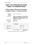
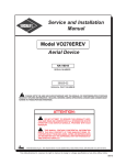
1
Propeller Technical Manual FOR C000242-Series Propellers 4A401A0D-Series Propellers C000262-Series Propellers DOCUMENT No. JPM3L1-3 DATED: 8th April 2014 Issue: 3 This Manual has been prepared as a guide to correctly operate & maintain Jabiru Propeller Models. It is the owner's responsibility to regularly check the Jabiru web site at www.jabiru.net.au for applicable Service Bulletins and have them implemented as soon as possible. Manuals are also updated periodically with the latest revisions available from the web site. Failure to maintain the engine or aircraft with current service information may render the aircraft un-airworthy and void Jabiru’s Limited, Express Warranty. This document is controlled while it remains on the Jabiru server. Once this no longer applies the document becomes uncontrolled. Should you have any questions or doubts about the contents of this manual, please contact Jabiru Aircraft Pty Ltd. Propeller Technical Manual JPM3L1-3 1.1 1.2 2 Jabiru Aircraft Pty Ltd C000242, C000262, 4A401 Propeller Variants TABLE OF FIGURES ............................................................................................................................................. 3 LIST OF TABLES .................................................................................................................................................. 3 GENERAL INFORMATION .................................................................................................................................... 4 2.1 FOREWORD ......................................................................................................................................................... 4 2.2 W ARNINGS .......................................................................................................................................................... 5 2.3 LIST OF EFFECTIVE PAGES................................................................................................................................. 6 2.4 READING THIS MANUAL ...................................................................................................................................... 6 2.5 DEGREE OF DIFFICULTY..................................................................................................................................... 6 2.6 APPLICABILITY..................................................................................................................................................... 6 2.6.1 Type Certified Models .............................................................................................................................. 6 2.6.2 Other Models ............................................................................................................................................ 7 2.7 APPROVED PROPELLER & ENGINE COMBINATIONS .......................................................................................... 7 2.8 MASS MOMENT OF INERTIA ................................................................................................................................ 7 3 PROPELLER OPERATION ................................................................................................................................... 8 3.1 LIMITATIONS ........................................................................................................................................................ 8 3.1.1 Maximum RPM ......................................................................................................................................... 8 3.1.2 Life .............................................................................................................................................................. 8 3.2 NORMAL OPERATIONS:....................................................................................................................................... 8 3.2.1 Ground Handling ...................................................................................................................................... 8 3.2.2 Hand Manoeuvring ................................................................................................................................... 8 3.2.3 Parking ....................................................................................................................................................... 8 3.2.4 Daily Inspection ........................................................................................................................................ 8 3.3 ABNORMAL OPERATIONS: .................................................................................................................................. 9 3.3.1 Running In Rain ........................................................................................................................................ 9 4 AIRWORTHINESS LIMITATIONS SECTION ................................................................................................... 10 5 PROPELLER MAINTENANCE ........................................................................................................................... 11 5.1 INTRODUCTION.................................................................................................................................................. 11 5.2 DESCRIPTION .................................................................................................................................................... 11 5.2.1 General .................................................................................................................................................... 11 5.2.2 Propeller Specifications ......................................................................................................................... 11 5.2.3 Type 1 Propeller Markings .................................................................................................................... 12 5.2.4 Type 2 Propeller Markings .................................................................................................................... 12 5.2.5 Type 1 Propeller Markings – 4A401 Series ........................................................................................ 12 5.2.6 Type 2 Propeller Markings – 4A401 Series ........................................................................................ 12 5.3 MAINTAINER REQUIREMENTS ........................................................................................................................... 13 5.4 TOOL & GAUGE CONTROL................................................................................................................................ 13 5.5 TOOLS & EQUIPMENT: ...................................................................................................................................... 13 5.6 CLEANING, GROUND HANDLING & STORAGE .................................................................................................. 13 5.6.1 Cleaning................................................................................................................................................... 13 5.6.2 Ground Handling .................................................................................................................................... 14 5.6.3 Parking ..................................................................................................................................................... 14 5.6.4 Off-Aircraft Storage ................................................................................................................................ 14 5.6.5 Returning Propeller to Service ............................................................................................................. 14 5.7 MAINTENANCE SCHEDULE ................................................................................................................................ 14 5.7.1 Service Interval Tolerance .................................................................................................................... 15 5.7.2 100-Hourly Inspection ............................................................................................................................ 16 5.7.3 Annual Inspection ................................................................................................................................... 16 5.7.4 Special Inspections: AD/PFP/1 ............................................................................................................ 16 5.8 MAINTENANCE PROCEDURES........................................................................................................................... 17 5.8.1 Acceptance Checking ............................................................................................................................ 17 5.8.2 Procedure – Removal of Existing Propeller ....................................................................................... 17 5.8.3 Procedure - Propeller installation ......................................................................................................... 17 5.8.4 Procedure – Propeller Tracking ........................................................................................................... 19 5.8.5 Procedure – Spinner Tracking.............................................................................................................. 19 5.8.6 Procedure – Propeller Balance (Maintenance) .................................................................................. 19 5.9 OPERATIONAL CHECKS .................................................................................................................................... 19 This document is controlled while it remains on the Jabiru server. Once this no longer applies the document becomes uncontrolled. ISSUE 1 2 3 Dated: 8th April 2014 Issued By: DS Page: 2 of 31 Propeller Technical Manual JPM3L1-3 Jabiru Aircraft Pty Ltd C000242, C000262, 4A401 Propeller Variants 5.10 TROUBLESHOOTING .......................................................................................................................................... 20 5.10.1 Defect Recognition ................................................................................................................................. 20 6 PROPELLER OVERHAUL .................................................................................................................................. 26 6.1 OVERHAULER REQUIREMENTS ......................................................................................................................... 26 6.2 TOOL & GAUGE CONTROL................................................................................................................................ 26 6.3 TOOLS & EQUIPMENT: ...................................................................................................................................... 26 6.3.1 Propeller Balancing Jig .......................................................................................................................... 26 6.4 OVERHAUL SEQUENCE ..................................................................................................................................... 27 6.5 PROPELLER REMOVED INSPECTIONS .............................................................................................................. 27 6.6 FITS & CLEARANCES ........................................................................................................................................ 28 6.6.1 Propeller Drive Bushes .......................................................................................................................... 28 6.7 REPAIR METHODS ............................................................................................................................................ 28 6.7.1 Propeller Balancing Procedure (Overhaul) ......................................................................................... 28 6.7.2 Damage Limits & Repairs ..................................................................................................................... 28 6.7.3 Nick Repair .............................................................................................................................................. 29 6.7.4 Urethane .................................................................................................................................................. 29 6.7.5 Fibreglass ................................................................................................................................................ 29 6.7.6 General .................................................................................................................................................... 30 7 APPENDIX A – WORKSHEETS ......................................................................................................................... 30 1.1 Table of Figures Figure 1 – Typical Propeller Installation .......................................................................................................... 18 Figure 2 – Trailing Edge Chip .......................................................................................................................... 20 Figure 3 – Hub Aging ....................................................................................................................................... 21 Figure 4 – Hub Compression Cracking ........................................................................................................... 21 Figure 5 – Stone Chip & Urethane Abrasion ................................................................................................... 22 Figure 6 – Urethane Abrasion ......................................................................................................................... 22 Figure 7 – Urethane Pitting .............................................................................................................................. 23 Figure 8 – Moisture Ingress – Leading Edge at Root. ..................................................................................... 23 Figure 9 – Resin Crack .................................................................................................................................... 24 Figure 10 – Fibreglass De-lamination .............................................................................................................. 25 Figure 11 – Fibreglass De-lamination .............................................................................................................. 25 Figure 12 – Propeller Balancing ...................................................................................................................... 27 1.2 List of Tables Table 1 – List of Approved Revisions ................................................................................................................ 6 Table 2 – The Spanner Scale ............................................................................................................................ 6 Table 3 – Inspection Chart............................................................................................................................... 15 This document is controlled while it remains on the Jabiru server. Once this no longer applies the document becomes uncontrolled. ISSUE 1 2 3 Dated: 8th April 2014 Issued By: DS Page: 3 of 31 Propeller Technical Manual Jabiru Aircraft Pty Ltd JPM3L1-3 C000242, C000262, 4A401 Propeller Variants 2 General Information 2.1 Foreword It is the owner’s responsibility to become fully aware of the particular maintenance requirements and limitations applicable to the propellers when used in their application. The information in this manual is based upon data available at the time of publication, and is supplemented and kept current by Service Bulletins & Service Letters published by JABIRU AIRCRAFT Pty Ltd. These are distributed directly to owners in addition to being posted on the JABIRU website or provided to your local Dealer or Distributor so that they have the latest authorised recommendations for servicing the propellers. New owners of pre-owned certified propellers should ensure that the transfer of ownership has been advised to JABIRU AIRCRAFT Pty Ltd or your local dealer or distributor. Existing owners should ensure that their postal address remains current. IMPORTANT All maintenance should be undertaken with careful regard for the procedures outlined in this manual. A detailed record of maintenance undertaken should be recorded in the Aircraft Log Books. Eligible JABIRU Type Certified Propellers described in this Technical Manual must be maintained by an Authorised Person (LAME for CASA-registered aircraft, Owner or Level 2 Holder for RA-Ausregistered aircraft). In all cases, NO MODIFICATIONS ARE PERMITTED without approval from a CAR 35 Authorised Person, the aircraft manufacturer or equivalent. It is the owner’s responsibility to ensure that their propeller is maintained by an appropriate person. Eligible JABIRU Propellers operating in the Light Sport Aircraft category must be maintained by an Authorised Person (LAME for CASA-registered aircraft, Owner or Level 2 Holder for RA-Ausregistered aircraft). In all cases, NO MODIFICATIONS ARE PERMITTED without approval from the propeller manufacturer. It is the owner’s responsibility to ensure that their propeller is maintained by an appropriate person. In the interests of product development, we encourage owners to make suggestions related to design improvements. However, the final decision on their adoption or otherwise rests with JABIRU AIRCRAFT Pty Ltd. This document is controlled while it remains on the Jabiru server. Once this no longer applies the document becomes uncontrolled. ISSUE 1 2 3 Dated: 8th April 2014 Issued By: DS Page: 4 of 31 Propeller Technical Manual JPM3L1-3 Jabiru Aircraft Pty Ltd C000242, C000262, 4A401 Propeller Variants 2.2 Warnings WARNING DO NOT GO NEAR THE PROPELLER IF THERE IS A PERSON IN OR NEAR THE COCKPIT. ENSURE AIRCRAFT MASTER SWITCH IS "OFF" BEFORE COMMENCING ANY WORK ON PROPELLER. DO NOT RUN ENGINE WITH PROPELLER DISCONNECTED OR ENGINE DAMAGE WILL RESULT. Jabiru Aircraft Pty Ltd has devoted significant resources and testing to develop the different Jabiru aircraft propellers for recreational flying and flight training. Any other uses or applications not approved by Jabiru Aircraft P/L may be extremely hazardous, leading to property damage, or injury or death of persons on or in the vicinity of the vehicle. Jabiru Aircraft Pty Ltd does not support the use of this propeller in any applications which do not meet the requirements of the appropriate Pilot Operating Handbook or Flight Manual. Any non-compliant operation may render the propeller & aircraft un-airworthy and will void any warranty issued by Jabiru. Jabiru Propellers are designed to be maintained only in strict accordance with this Technical Manual. Any variation of any kind, including alteration to any component at all, whether replacement, relocation, modification or otherwise which is not strictly in accordance with these manuals may lead to dramatic changes in the performance of the aircraft and may cause unexpected engine stoppage, loss of control or have other detrimental effects on the aircraft which may lead to injury or death. Jabiru Aircraft Pty Ltd does not support any modifications to the propeller, its parts, or components. Any such actions may render the propeller & aircraft un-airworthy and will void any warranty issued by Jabiru. Maintenance and modification cannot be supervised by the manufacturer. Maintenance requires extreme cleanliness, exact parts, precise workmanship and proper consumables. It is your responsibility to ensure absolute attention to detail no matter who may become involved in work on this propeller. Your safety, your life and your passenger’s lives rely on precise and accurate following of instructions in this manual. In exchange for the technical manual provided by Jabiru Aircraft Pty. Ltd. (“Jabiru”) I hereby agree to waive, release, and hold Jabiru harmless from any injury, loss, damage, or mishap that I, my spouse, heirs, or next of kin may suffer as a result of my use of any Jabiru product, except to the extent due to gross negligence or willful misconduct by Jabiru. I understand that proper skills and training are essential to minimize the unavoidable risks of property damage, serious bodily injury and death that arise from the use of Jabiru products. IMPORTANT Always think before acting. Use common sense. WORKING WITH PROPELLERS CAN BE EXTREMELY DANGEROUS. This document is controlled while it remains on the Jabiru server. Once this no longer applies the document becomes uncontrolled. ISSUE 1 2 3 Dated: 8th April 2014 Issued By: DS Page: 5 of 31 Propeller Technical Manual JPM3L1-3 Jabiru Aircraft Pty Ltd C000242, C000262, 4A401 Propeller Variants 2.3 List of Effective Pages This manual is revised as a whole. All pages retain the revision status of the overall document. Altered technical content is shown in red. Table 1 – List of Approved Revisions Original Issue – 2008 2012 – Updated to include other propeller models. Layout & content aligned with 2012 Jabiru Manual Format. 1 2 Maintainer requirements and formatting added as prescribed by ASTM F2483-12 More detailed and extensive worksheet added 3 2.4 Reading This Manual This manual is intended for use by experienced technicians and while all processes will be explained as clearly as possible, some knowledge is assumed. This manual is not intended to be sufficient reference for a person with no other training to safely maintain or overhaul a propeller. If you are reading this manual on a computer and want to be able to quickly zoom in and out: Hold down the Ctrl key while rotating the wheel button on your mouse. In most programs this will instantly zoom in or out. To do the same thing on a modern laptop either plug in a wheel mouse as detailed above or use the builtin track-pad. Put two fingers on the pad close together then move then apart diagonally. To reverse, put two fingers on the pad at opposite diagonal points on the pad and bring them together diagonally. This works on most modern PC-laptops. This document has been created with hyperlinks between referenced items. So, when reading the manual on a computer you can click on the page number of an item on the table of contents and the computer will skip to that page. Also, if a paragraph says “refer to Section 5.1” – then you can click on the “5.1” and automatically skip to that page. Similarly, if Figures or Tables are referenced. To open a search window press “Ctrl-f”. Depending on the program, this will normally open a small search window where you can enter keywords. For example, searching for the word “life” will allow you to quickly find all reference to lifed maintenance items. 2.5 Degree Of Difficulty In this manual we have used a “spanner scale” to help overhaulers approach a job. Anyone considering undertaking a task in this manual must realistically assess themselves against this scale and not attempt any task for which they lack knowledge or the required tools. Table 2 – The Spanner Scale The Spanner Scale Translation Simple, basic, straightforward. A careful layman, with guidance, can achieve this. Straightforward, but with some technical bits. Basic knowledge, care and guidance needed. Straightforward, but requires special tools, training and/or judgement. Sound basic knowledge guidance and a careful approach are required. A technical job. Take your time, double-check everything. Only for the experienced overhauler. A difficult job. Requires special tools, solid skills, good judgement. Only for experts. 2.6 Applicability 2.6.1 Type Certified Models This manual contains JABIRU recommended procedures and instructions for ground handling, servicing and maintaining the following Jabiru propeller models: This document is controlled while it remains on the Jabiru server. Once this no longer applies the document becomes uncontrolled. ISSUE 1 2 3 Dated: 8th April 2014 Issued By: DS Page: 6 of 31 Propeller Technical Manual JPM3L1-3 C000242-D60P38 C000242-D60P42 C000242-D60P44 4A401B0D 4A401A0D 4A401C0D Jabiru Aircraft Pty Ltd C000242, C000262, 4A401 Propeller Variants - Jabiru 4 Cylinder Propeller (3 lamination, Ø60” pitch 38”) Jabiru 4 Cylinder Propeller (3 lamination, Ø60” pitch 42”) Jabiru 4 Cylinder Propeller (3 lamination, Ø60” pitch 44”) Jabiru 4 Cylinder Propeller (3 lamination, Ø60” pitch 38”) Jabiru 4 Cylinder Propeller (3 lamination, Ø60” pitch 42”) Jabiru 4 Cylinder Propeller (3 lamination, Ø60” pitch 44”) C000242 propellers from S/No. 2900 onwards and 4A401 propellers from S/No. 002 onwards meet the applicability requirements for Australian Type Certificate, Number VP503, issued by the Civil Aviation Safety Authority (CASA) of Australia. 2.6.2 Other Models This manual also contains JABIRU recommended procedures and instructions for ground handling, servicing and maintaining the following Jabiru propeller models: C000262-D60P44 C000262-D60P48 C000262-D60P53 C000262-D60P55 - Jabiru 6 Cylinder Propeller (4 lamination, Ø60” pitch 44”) Jabiru 6 Cylinder Propeller (4 lamination, Ø60” pitch 48”) Jabiru 6 Cylinder Propeller (4 lamination, Ø60” pitch 53”) Jabiru 6 Cylinder Propeller (4 lamination, Ø60” pitch 55”) These propellers are not type certified, though certain serial numbers claim compliance with the requirements of CS-22 Subpart J or ASTM F2506-10 for operations in Light Sport Aircraft (LSA) category aircraft. All propellers listed are certified for use on Jabiru 3300 Aircraft Engines. 2.7 Approved Propeller & Engine Combinations C000242 and 4A401 propellers are approved for use on all variants of the Jabiru 2200 Aircraft Engine only. C000262 propellers are approved for use on all variants of the Jabiru 3300 Aircraft Engine only. 2.8 Mass Moment of Inertia 0.2 – 0.3kgm 2 This document is controlled while it remains on the Jabiru server. Once this no longer applies the document becomes uncontrolled. ISSUE 1 2 3 Dated: 8th April 2014 Issued By: DS Page: 7 of 31 Propeller Technical Manual Jabiru Aircraft Pty Ltd JPM3L1-3 C000242, C000262, 4A401 Propeller Variants 3 Propeller Operation 3.1 Limitations 3.1.1 Maximum RPM All propellers covered by this manual are limited to 3300 RPM. 3.1.2 Life The propellers are assessed on condition. There is no fixed life. 3.2 Normal Operations: 3.2.1 Ground Handling Impact from gravel, grass, insects and other objects can damage the propeller. When operating from gravel runways the pilot should be aware of this at all times and plan their operations to suit. Take care when carrying out ground tests of the engine – either make sure the propeller is not over any loose gravel or perform run-ups while rolling forwards at normal taxi speed (note that this procedure requires some practice and is not recommended for student pilots). Unless required due to short runway length, do not hold the aircraft on the brakes while increasing power at the start of the takeoff roll. Take care when taxiing through ditches or over rough or uneven ground. Reduce speed, pass over the ditch diagonally and do not abruptly increase power to climb out the far side. If unsure, stop the engine and push the aircraft across the ditch by hand. 3.2.2 Hand Manoeuvring The aircraft may be moved by hand using the propeller as a handle. However, the following procedures must be used: IMPORTANT Always think before acting and use common sense. Working with propellers can be extremely dangerous. Ensure that the aircraft’s master switch is OFF before walking near the propeller Do not go near the propeller if there is a person in or near the cockpit. Only one person at a time may hold the propeller. Always hold the propeller as close as possible to the root – in practice this normally means placing hands immediately beside the spinner. Orient the propeller horizontally unless manoeuvring the aircraft past an obstruction which would hit the propeller if it were left horizontal. However, do not park the propeller in a vertical orientation (see notes below – Section 3.2.3) 3.2.3 Parking To prevent the accumulation of moisture in the lower blade, the propeller must always be left in the horizontal position when the engine is being parked for any length of time, especially in conditions of high ambient humidity. 3.2.4 Daily Inspection Inspect both blades for: Urethane condition: peeling, tears, pitting or abrasion. Fibreglass condition: stone chips, trailing edge chips, de-laminations, whitening. Resin condition: cracks. Pictures of typical damage are shown in Section 5.10.1. This document is controlled while it remains on the Jabiru server. Once this no longer applies the document becomes uncontrolled. ISSUE 1 2 3 Dated: 8th April 2014 Issued By: DS Page: 8 of 31 Propeller Technical Manual JPM3L1-3 Jabiru Aircraft Pty Ltd C000242, C000262, 4A401 Propeller Variants 3.3 Abnormal Operations: 3.3.1 Running In Rain Jabiru Aircraft do not recommend or endorse operating in rain. The following is intended as a guide for owners who have, for whatever reason, been forced to fly through rain. Do not operate in heavy rain or hail. Know your limitations and the limitations of your aircraft. If in doubt, divert or land. Maintain situational awareness – do not fly into rising terrain or near high obstacles (radio towers etc) in low visibility conditions. If forced to fly through rain reduce engine RPM. 2600rpm or less is recommended – though the pilot must maintain a safe airspeed. Monitor propeller condition – on landing check the blades for damage. Minor damage can be repaired in the field in accordance with the details given in Section 6.7.2. Do not fly on with damage beyond the limits set in Section 6.7.2. A Urethane leading edge is provided for impact protection and also allows the propeller to be run in rain if required. However, the propeller is not intended for extended operation in heavy rain. Running in heavy rain will erode the Urethane – reducing the efficiency of the propeller blade and upsetting its balance. After extended running in rain the Urethane may become so badly worn that the fibreglass leading edge underneath is exposed. Once exposed, the fibreglass will quickly be damaged by continued operation in rain. It is possible that a propeller which has been damaged to this extent may suffer fibreglass delamination from a blade – massively reducing propeller efficiency and increasing vibration to the point where the engine must be shut down. This makes continued operation with exposed fibreglass edges extremely hazardous. This document is controlled while it remains on the Jabiru server. Once this no longer applies the document becomes uncontrolled. ISSUE 1 2 3 Dated: 8th April 2014 Issued By: DS Page: 9 of 31 Propeller Technical Manual JPM3L1-3 Jabiru Aircraft Pty Ptd C000242 and 4A401 Propeller Variants Airworthiness Limitations Section – CASA Approved 4 Airworthiness Limitations Section THIS AIRWORTHINESS LIMITATIONS SECTION IS APPROVED BY THE CIVIL AVIATION SAFETY AUTHORITY OF AUSTRALIA. IT SPECIFIES THE AIRWORTHINESS LIMITATIONS REQUIRED TO MAINTAIN COMPLIANCE WITH THE CERTIFICATION BASIS AS SPECIFIED IN THE TYPE CERTIFICATE NO. VP503 (CASR Part 35 per FAA FAR 35 STANDARD and CAO 101.55 REGULATIONS). There are no Airworthiness Limitations applicable to the Jabiru C000242 and 4A401 series propellers. Signature: For Civil Aviation Safety Authority. Date: This document is controlled while it remains on the Jabiru server. Once this no longer applies the document becomes uncontrolled. ISSUE 1 2 3 Dated: 8th April 2014 Issued By: DS Page: 10 of 31 Propeller Technical Manual Jabiru Aircraft Pty Ltd JPM3L1-3 C000242, C000262, 4A401 Propeller Variants 5 Propeller Maintenance 5.1 Introduction The Jabiru Propellers detailed in this manual are 2-bladed fixed pitch designs constructed of wood / fibreglass composite. They are available in a range of different pitches. WARNING ENSURE IGNITION SYSTEM IS "OFF" BEFORE COMMENCING ANY WORK ON PROPELLER. DO NOT RUN ENGINE WITH PROPELLER DISCONNECTED OR ENGINE DAMAGE WILL RESULT. 5.2 Description 5.2.1 General The Jabiru Propellers detailed in this manual are made from plantation Hoop Pine sheathed in fibreglass. A Urethane protective coating is applied to the leading edge of both blades. The propeller finish is normally clear enamel paint, though other colours may be used for some applications. 5.2.2 Propeller Specifications Note that approved propeller and engine combinations are detailed in Section 2.7 Propeller Model & Drawing Number Engine Max Power C000242-D60P38 2200 Variants 85hp C000242-D60P42 2200 Variants 85hp C000242-D60P44 2200 Variants 85hp 2200 Variants 2200 Variants 2200 Variants 3300 Variants 3300 Variants 3300 Variants 3300 Variants 4A401B0D 4A401A0D 4A401C0D C000262-D60P44 C000262-D60P48 C000262-D60P53 C000262-D60P55 85hp 85hp 85hp 120hp 120hp 120hp 120hp Propeller Flange Std – 4525064 2” Ext – 4610074 2” Ext – 466218N Std – 4525064 2” Ext – 4610074 2” Ext – 466218N Std – 4525064 2” Ext – 4610074 2” Ext – 466218N Std – 4662084 2” Ext – 466218N Std – 4662084 2” Ext – 466218N Std – 4662084 2” Ext – 466218N Std – 4662084 2” Ext – 466218N Std – 4662084 2” Ext – 466218N Std – 4662084 2” Ext – 466218N Std – 4662084 2” Ext – 466218N Dia x Pitch Remarks/Limits 1524 x 965 (60” x 38”) Not above 3300 RPM 1524 x 1067 (60” x 42”) Not above 3300 RPM 1524 x 1118 (60” x 44”) Not above 3300 RPM 1524 x 965 (60” x 38”) 1524 x 1067 (60” x 42”) 1524 x 1118 (60” x 44”) 1524 x 1118 (60” x 44”) 1524 x 1219 (60” x 48”) 1524 x 1346 (60” x 53”) 1524 x 1397 (60” x 55”) Not above 3300 RPM Not above 3300 RPM Not above 3300 RPM Not above 3300 RPM Not above 3300 RPM Not above 3300 RPM Not above 3300 RPM This document is controlled while it remains on the Jabiru server. Once this no longer applies the document becomes uncontrolled. ISSUE 1 2 3 Dated: 8th April 2014 Issued By: DS Page: 11 of 31 Jabiru Aircraft Pty Ltd Propeller Technical Manual JPM3L1-3 C000242, C000262, 4A401 Propeller Variants 5.2.3 Type 1 Propeller Markings Each propeller is marked with the particulars indicated below: DWG C000242-D60P42 D 1524 P 1067 JABIRU 2200 J J 4 0001 L C Drawing No. Diameter Engine Model Jabiru Prop. Jabiru Engine Pitch Composite Sheath 4 = 4 Cylinder 6 = 6 Cylinder Serial No. Leading Edge Protection 5.2.4 Type 2 Propeller Markings Type 2 data tags are fitted to the rear face of the blade just outboard of the spinner. Drawing No. Pitch Diameter Composite Sheath Engine Model Jabiru Prop. Jabiru Engine 4 = 4 Cylinder 6 = 6 Cylinder Serial No. Leading Edge Protection 5.2.5 Type 1 Propeller Markings – 4A401 Series Each propeller is marked with the particulars indicated below: Drawing No. Diameter Engine Model DWG 4A401A0D D 1524 P 1067 JABIRU 2200 J4A401 0001 LC Pitch Composite Sheath Prop Model Descriptor Serial No. Leading Edge Protection 5.2.6 Type 2 Propeller Markings – 4A401 Series Type 2 data tags are fitted to the rear face of the blade just outboard of the spinner. Drawing No. Pitch Diameter Composite Sheath Engine Model Jabiru Prop. Prop Model Descriptor Serial No. Leading Edge Protection This document is controlled while it remains on the Jabiru server. Once this no longer applies the document becomes uncontrolled. ISSUE 1 2 3 Dated: 8th April 2014 Issued By: DS Page: 12 of 31 Propeller Technical Manual Jabiru Aircraft Pty Ltd JPM3L1-3 C000242, C000262, 4A401 Propeller Variants 5.3 Maintainer Requirements The following are recommended as the minimum requirements for someone carrying out maintenance & inspection on Jabiru Propellers: 1. Facilities - Enclosed workspace with sealed floor, lighting, compressed air & mains electricity. 2. Training - Completion of an approved instruction course specific to Jabiru Aircraft. Approved courses include those offered by Jabiru Aircraft Australia or by local Jabiru Aircraft representatives. 3. Rating - Commercial maintainers must hold ratings required by their local Airworthiness Authority. 4. Experience - A minimum of 2 years experience working on aircraft under supervision is recommended for commercial maintainers before working un-supervised. 5.4 Tool & Gauge Control Tool & gauge control is an important part of aviation maintenance systems. Tools & gauges must be accurate enough for the intended use (i.e. a 12” steel ruler is not the appropriate tool to use to measure the thickness of the middle of the propeller blade) & be accurately calibrated by an approved laboratory. Calibrations must be kept up to date. This means a check calibration every year or more frequently for regularly used, critical tooling. Even quality equipment will wear over time so items like reams and go / no-go gauges must periodically be checked to ensure they remain within limits. 5.5 Tools & Equipment: Access to the following tools will be required. All tools must be good quality items: Ring/open end spanner: 7/16” Ratchet 3/8” drive, 2” extension bar, 7/16” socket Screwdrivers: flat blade and Phillips head in various sizes Torque wrench: 3/8” drive, “name” brand (Snap-On, Warren & Brown etc), recently calibrated. The wrench must have a suitable scale for use on the fasteners typically found on Jabiru Access to the following equipment will be required: Bench vice with padded jaws Calipers Saw-horses Accurate level / protractor Propeller balance jig Rags, soft mallet, hammers TorqueSeal brand security marking lacquer or similar, such as coloured nail varnish 5-Minute epoxy resin, Jabiru epoxy resin, cotton fibre flock, Q-cells (micro-balloons), containers, scales, mixers etc. 5.6 Cleaning, Ground Handling & Storage 5.6.1 Cleaning Keeping the propeller clean is important. Besides maintaining the appearance of the aircraft, cleaning makes inspection and maintenance easier. Generally, the exterior surfaces can be kept bright by washing with water and a mild soap or detergent, followed by a rinse with water and drying with a cloth or a chamois. Remove stubborn oil and grease with a cloth moistened with mineral turpentine, then wash with water and a mild soap, rinse and dry as stated before. This document is controlled while it remains on the Jabiru server. Once this no longer applies the document becomes uncontrolled. ISSUE 1 2 3 Dated: 8th April 2014 Issued By: DS Page: 13 of 31 Propeller Technical Manual Jabiru Aircraft Pty Ltd JPM3L1-3 C000242, C000262, 4A401 Propeller Variants CAUTION DO NOT use Silicon based cleaning materials as Silicon is absorbed into the composite materials and may affect reparability. CAUTION Do not use a wax based substance as this would make it almost impossible to refurbish the prop if needed at a later stage. 5.6.2 Ground Handling All Jabiru aircraft are relatively light and should always be moved by hand. The aircraft may also be moved by placing the propeller in the horizontal and then placing one hand on the propeller on either side of the spinner. The aircraft can then be pulled forward. WARNING Never move the aircraft in this manner whilst the engine is hot as it may fire when the propeller is moved and result in severe injury. Always ensure that the Master and Ignitions are OFF. Never approach the propeller when anyone is in the aircraft. Always treat the propeller as LIVE! IT KILLS! 5.6.3 Parking It is strongly recommended that aircraft are stored in hangars wherever possible to minimise degradation caused by the elements and pests. When parking the aircraft always orient the propeller with the blades horizontal to prevent gravity-fed moisture migration to the lower blade. The propeller is susceptible to UV damage and should be covered if the aircraft is to be stored outside long-term. 5.6.4 Off-Aircraft Storage The propeller must always be stored horizontally to minimse uneven moisture accumulation in the blades, causing imbalance. Where possible the propeller should be stored at above 0°C (freezing). Propellers may be stored horizontally on any flat, dry shelf or surface. Propellers should be positioned so that they are resting on the drive face. Ensure no items are resting or leaning against the propeller. Ensure the propeller is not subjected to direct sunlight. Minimise the propeller’s exposure to humidity while in storage As much as possible minimise the propeller’s exposure to changes in temperature & humidity. 5.6.5 Returning Propeller to Service When a propeller which has been stored is returned to service the following must be checked: Propeller balance Fit of drive bushes into propeller hub: must be a close fit with no free-play. Condition of the propeller timer, composite, leading edge protection & leading edge tape (where equipped). If the propeller has been stored for more than a year it is recommended that it be returned to Jabiru Aircraft or an authorised service centre to check the blade pitches. 5.7 Maintenance Schedule Note that while the spinner assembly is not considered a part of the propeller, some spinner inspections are included below for reference. The chart below shows the recommended intervals at which items are to be inspected. Additional detail of the maintenance required in each section is given below the inspection chart. As shown in the chart, there are items to be inspected each 100 hours and Annually. When conducting an inspection at 100 hours, all items marked under Each 100 Hours is inspected, serviced or otherwise completed. This document is controlled while it remains on the Jabiru server. Once this no longer applies the document becomes uncontrolled. ISSUE 1 2 3 Dated: 8th April 2014 Issued By: DS Page: 14 of 31 Propeller Technical Manual JPM3L1-3 Jabiru Aircraft Pty Ltd C000242, C000262, 4A401 Propeller Variants An inspection conducted annually includes the 100 hour items in addition to the items marked under Annual Inspection. A complete propeller inspection includes all 100 hour and Annual items together. 5.7.1 Service Interval Tolerance A tolerance of plus or minus 3 hours is allowable on all service intervals set within this manual Table 3 – Inspection Chart Annual Inspection Each 100 Hours SPINNER General condition – cracks etc. 1 Screw holes are not excessively elongated 2 * * * * SPINNER FLANGE 3 General condition – cracks around perimeter of hub etc * * 4 Anchor nuts & rivets secure * * 5 Visual inspection for signs of fretting / looseness * * 6 Head & thread condition * * 7 Tightness of screw in nut. Replace anchor nuts if loose. * * 8 Urethane condition – Refer Section 6.7.2 for details. * * 9 fiberglass condition – Refer Section 6.7.2 for details. * * 10 Wood condition – Refer Section 6.7.2 for details. * * 11 Hub condition – Refer Section 6.7.2 for details. * * 12 Propeller Drive Bush Fit – Refer Section 6.6.16.7.2 for details. SPINNER SCREWS PROPELLER * PROPELLER BOLTS / NUTS 13 Condition – corrosion etc. * * 14 Bolt / Nut tension * * 15 Propeller tracking * * 16 Spinner tracking * * TRACKING BALANCE 17 Check Propeller Balance 18 SPECIAL INSPECTIONS: Refer to Section 5.7.4 * This document is controlled while it remains on the Jabiru server. Once this no longer applies the document becomes uncontrolled. ISSUE 1 2 3 Dated: 8th April 2014 Issued By: DS Page: 15 of 31 Propeller Technical Manual Jabiru Aircraft Pty Ltd JPM3L1-3 C000242, C000262, 4A401 Propeller Variants 5.7.2 100-Hourly Inspection As all possible circumstances cannot be listed here, the following is provided as guidance only. A critical, trained eye is required and inspections should include, but not be limited to, the following. Remove the spinner and carry out a thorough visual inspection checking for cracking, fraying, corrosion and other damage. Check for loose, missing, corroded or damaged fasteners and hardware. Check for deposits and radial markings which indicate fretting between moving parts. Visually check the condition of the propeller, looking for damage to the leading edge protection, glass delamination and cracks, splits or crushing of the propeller timber. Check the tension of the propeller bolts/nuts – Tension if required. Check spinner and Prop Tracking. 5.7.3 Annual Inspection Annual inspections include all the items listed for the 100-hourly inspection above plus the additional items below. As all possible circumstances cannot be listed here, the following is provided as guidance only. A critical, trained eye is required and inspections should include, but not be limited to, the following. Remove the propeller from the aircraft. Carry out the inspections detailed in Section 6.4. Thoroughly check the propeller for cracking, wear or damage – particularly in those areas not visible while the propeller is mounted to the engine. Ensure the propeller does not exceed the wear & damage limits detailed in Section 5.10. Test the fit of the propeller drive bushes as detailed in Section 6.6.1 Check the propeller balance as detailed in Section 5.8.4 5.7.4 Special Inspections: AD/PFP/1 CASA Airworthiness Directive AD/PFP/1 is applicable to the propellers detailed herein. Operators & Maintainers must ensure that the propeller is maintained in accordance with the latest revision of this AD. Amendment 3 was current at the time of writing. This requires the following inspections: - Check propeller tracking - Check hub bolts for tightness - Inspect sheathing and tipping for looseness, separation, loose screws, cracks or corrosion. These inspections must be carried out: - After the first flight following each installation - At intervals not exceeding 100 hours time in service from installation or twelve months whichever occurs first. Jabiru Aircraft also require that these inspections be carried out: - When there has been a significant change in the ambient humidity due to a seasonal change or change in aircraft locality and, - Prior to the first flight after the aircraft has been idle for an extended period. This document is controlled while it remains on the Jabiru server. Once this no longer applies the document becomes uncontrolled. ISSUE 1 2 3 Dated: 8th April 2014 Issued By: DS Page: 16 of 31 Jabiru Aircraft Pty Ltd Propeller Technical Manual JPM3L1-3 C000242, C000262, 4A401 Propeller Variants 5.8 Maintenance Procedures 5.8.1 Acceptance Checking Type of Maintenance: Level of Certification: Line Maintenance LSA Repairman (Inspection of Maintenance) Propellers supplied by Jabiru Aircraft are balanced before shipping. Balancing before fitting to an aircraft is not necessary. Visually inspect propeller to ensure that it has not been damaged in transit. Before fitting, check that the propeller drive bushes are a neat fit in the sockets of the propeller. Section 6.6.1 gives details. 5.8.2 Procedure – Removal of Existing Propeller Type of Maintenance: Level of Certification: Line Maintenance LSA Repairman (Inspection of Maintenance) Figure 1 shows a typical propeller installation. 1. 2. 3. 4. Remove Machine Screws and Tinnerman Washers from Spinner. Remove Spinner. Unbolt Propeller Bolts - 6 off. Remove Bolts, Spinner Flange, Aluminium Propeller Flange, Belleville Washers and Propeller. 5.8.3 Procedure - Propeller installation Type of Maintenance: Level of Certification: 1. 2. Line Maintenance LSA Repairman (Inspection of Maintenance) Figure 1 shows typical propeller installation details. Ensure that Propeller drive bushes – 6 off, are in place in the Crankshaft Propeller Flange. Where equipped, fit the rear spinner backing plate to the flange. When switched off, Jabiru engines tend to come to rest with the flywheel magnets aligned with the ignition coils. When fitting a propeller turn the crank of the engine by hand until the magnets are aligned and then fit the propeller with the blades horizontal. This method makes it likely that when the engine is turned off the propeller will naturally tend to come to rest with the blades horizontal. Fit propeller to flange. Ensure that the drive pins are snug fit in the propeller. Fit Propeller Bolts - 6 off. Fit front spinner backing plate to front of propeller. Fit Aluminium Propeller Flange, Belleville Washers - 42 off: (8 per Bolt: assembled in pairs as shown) Progressively tighten bolts ensuring equal distribution of load and in a normal criss-cross torque sequence. Using Torque Wrench, tighten Bolts to 6lb.ft (72 inch/lbs). Check tracking of Propeller as detailed in Section 5.8.4. Locate Spinner on Spinner Flange and fix with Machine Screws through tinnerman Washers. Check Spinner tracking as detailed in Section 5.8.5 Leading edge tape can be applied between the inner edge of the urethane leading edge and the spinner. This optional tape protects the propeller and reduces the chances of moisture ingress. After the first flight following the propeller installation the spinner must be removed and the propeller bolts checked for correct tension. 3. 4. 5. 6. 7. 8. 9. 10. 11. 12. 13. This document is controlled while it remains on the Jabiru server. Once this no longer applies the document becomes uncontrolled. ISSUE 1 2 3 Dated: 8th April 2014 Issued By: DS Page: 17 of 31 Propeller Technical Manual JPM3L1-3 Jabiru Aircraft Pty Ltd C000242, C000262, 4A401 Propeller Variants Figure 1 – Typical Propeller Installation IMPORTANT For all Jabiru Aircraft Engines the spinner is an important and integral part of the propeller Assembly. It is essential to ensure adequate engine cooling. The aircraft must not be flown with the spinner removed. This document is controlled while it remains on the Jabiru server. Once this no longer applies the document becomes uncontrolled. ISSUE 1 2 3 Dated: 8th April 2014 Issued By: DS Page: 18 of 31 Jabiru Aircraft Pty Ltd Propeller Technical Manual JPM3L1-3 C000242, C000262, 4A401 Propeller Variants 5.8.4 Procedure – Propeller Tracking Type of Maintenance: Level of Certification: 1. 2. 3. 4. 5. Line Maintenance LSA Repairman (Inspection of Maintenance) Locate a fixed object on a flat floor so that it clears the Propeller tips by a small margin – 1-3mm. Rotate the Propeller by hand. Check that each blade clears the object by the same amount. Measure the clearance for each blade. Maximum Tracking Error Tolerance is +/- 2mm. If the Propeller is outside the approved tolerance, refer to JABIRU Aircraft Pty Ltd or a JABIRU Approved Service Centre for rectification instructions. 5.8.5 Procedure – Spinner Tracking Type of Maintenance: Level of Certification: 1. 2. 3. Line Maintenance LSA Repairman (Inspection of Maintenance) Locate a fixed object on a flat floor to just clear the lower edge of the tip of the Spinner. Rotate the propeller by hand and check that the Spinner runs true. Correct any run-out by loosening machine screws, realigning spinner then retightening machine screws. 5.8.6 Procedure – Propeller Balance (Maintenance) Type of Maintenance: Level of Certification: 1. Line Maintenance LSA Repairman, Task specific training Propeller balancing in the course of maintenance follows the same procedure as during a propeller overhaul. Therefore the procedure given in Section 6.7.1 must be used. 5.9 Operational Checks Type of Maintenance: Level of Certification: Line Maintenance LSA Repairman (Inspection of Maintenance) For Type Certified C000242-D60P42 or 4A401A0D propellers, full power RPM with the aircraft stationary is 2800rpm ±50rpm For other C000242 or 4A401 propellers Full power RPM with the aircraft stationary is 2700rpm – 2950rpm For C000262 propellers Full power RPM with the aircraft stationary is 2600rpm – 2800rpm This document is controlled while it remains on the Jabiru server. Once this no longer applies the document becomes uncontrolled. ISSUE 1 2 3 Dated: 8th April 2014 Issued By: DS Page: 19 of 31 Propeller Technical Manual JPM3L1-3 Jabiru Aircraft Pty Ltd C000242, C000262, 4A401 Propeller Variants 5.10 Troubleshooting 5.10.1 Defect Recognition 5.10.1.1 Trailing Edge Chip Figure 2 below shows a minor trailing edge chip, approximately 13mm (0.5”) long. This type of damage is normally caused in the hangar or while the propeller is in storage or being shipped. Recommended Actions: In general, whitening is a sign that the resin matrix surrounding the fibreglass has been damaged. This type of damage can allow moisture to enter and act as a starting point from which de-laminations can grow. If the fibreglass has been chipped or frayed apply a thin type of superglue to the fibres. Capillary action will draw the glue into the glass and the colour will change from white to translucent. If the line of the trailing edge has been notched by a small amount (up to 2mm) the notch can be sanded away to leave a smooth trailing edge. This must be done AFTER the glass weave has been stabilised with superglue. Maximum size to repair by the method above: 13mm along the blade and extending up to 10mm towards the blade leading edge. After repair: visually monitor the chip for growth. Figure 2 – Trailing Edge Chip This document is controlled while it remains on the Jabiru server. Once this no longer applies the document becomes uncontrolled. ISSUE 1 2 3 Dated: 8th April 2014 Issued By: DS Page: 20 of 31 Propeller Technical Manual JPM3L1-3 5.10.1.2 Jabiru Aircraft Pty Ltd C000242, C000262, 4A401 Propeller Variants Propeller Hub Aging Figure 3 below shows an older propeller hub. Several small cracks are visible extending along the blade from the hub bolts. This type of damage is typically caused by over-torquing the propeller bolts (or not using Belleville washers on the installation as shown in Figure 1). Recommended Actions: Ensure the propeller is installed as detailed in Figure 1. Check the fit of the propeller drive bushes in the sockets is not loose. Measure the length of the cracks & compare to the limits shown below. Maximum crack length outside central zone (beyond lines) 50mm (2”) or up to the edge of the propeller. If the crack touches the side of the prop it must be visible down the side of the hob for no more than 10mm. (0.39”) Line through centres of outer bolt holes. Maximum crack length within central zone (between lines) 25mm (1”) Line through centres of outer bolt holes. Maximum crack length outside central zone (beyond lines) 50mm (2”) or up to the edge of the propeller. If the crack touches the side of the prop it must be visible down the side of the hob for no more than 10mm. (0.39”) Figure 3 – Hub Aging Figure 4 below shows the side of an older propeller hub. A crack running along the grain is visible. This type of damage is typically caused by over-torquing the propeller bolts (or not using Belleville washers on the installation as shown in Figure 1). Recommended Actions: Check the propeller installation & verify bolt tensions. Where the crack has exposed the wood, seal it using a thin type superglue to prevent moisture ingress. Overall propeller hub thickness must be greater than 58mm for 3-laminate propellers (shown) or 78mm for 4-laminate propellers. Crack Figure 4 – Hub Compression Cracking This document is controlled while it remains on the Jabiru server. Once this no longer applies the document becomes uncontrolled. ISSUE 1 2 3 Dated: 8th April 2014 Issued By: DS Page: 21 of 31 Propeller Technical Manual Jabiru Aircraft Pty Ltd JPM3L1-3 5.10.1.3 C000242, C000262, 4A401 Propeller Variants Urethane Abrasion, Stone Chips Figure 5 below shows a stone chip and urethane abrasion near the tip of a propeller blade. In this case some superglue has been applied to the stone chip. This sort of damage is generally caused by operations from gravel runways and flying through rain. Recommended Actions: Stone chips like the one shown below are not generally dangerous, however they should be visually monitored during normal daily inspections as it is possible for glass de-laminations to start from them. Using a thin type of superglue to seal the chip is recommended to seal the damage & stabilise the chip. The urethane damage shown below is minor. The edge of the fibreglass is not exposed and there are no loose sections of urethane. Note: due to the abrasion of the urethane this propeller tip will be much more susceptible to damage when flying through rain than it would be if the urethane was in as-new condition. Stone chip Abraded & damaged urethane Figure 5 – Stone Chip & Urethane Abrasion Figure 6 below shows more severe damage to the urethane. This type of damage is generally caused by flying through rain or taxiing through long grass. Recommended Actions: Urethane loss such as shown below is low-medium level damage. The leading edge of the fibreglass has been exposed and while the edges of the urethane appear stable they are irregularly shaped and may begin peeling. A propeller tip in this condition is safe in normal use, however it will be damaged much more rapidly by rain. The irregular ends of the urethane can be carefully removed with a sharp knife and the exposed edge of the fibreglass should be specifically checked during daily inspections. Remove these isolated pieces of urethane Trim line for urethane edges Figure 6 – Urethane Abrasion This document is controlled while it remains on the Jabiru server. Once this no longer applies the document becomes uncontrolled. ISSUE 1 2 3 Dated: 8th April 2014 Issued By: DS Page: 22 of 31 Propeller Technical Manual JPM3L1-3 5.10.1.4 Jabiru Aircraft Pty Ltd C000242, C000262, 4A401 Propeller Variants Urethane Pitting Figure 7 below shows urethane which has been pitted by flying through rain. Recommended Actions: Minor damage can be sanded slightly to improve the smoothness of the leading edge. The pits shown would be treated this way. Major damage must be repaired by replacing the urethane leading edge protection. Figure 7 – Urethane Pitting 5.10.1.5 Resin Cracks Figure 8 below shows cracking in the resin shell of the propeller at the leading edge between the inboard end of the urethane and the start of the spinner. The example shown is also fitted with leading edge prop tape. This damage is usually caused by moisture ingress into the blade causing the wood to swell and crack the resin coating. The moisture can enter whenever the blade is exposed to water: flying through rain, covered by dew overnight etc. Recommended Actions: The damage shown below is a minor example of its type. At this stage it should be covered with prop tape and monitored. If the cracking progresses any open cracks should be sealed with a thin type of superglue. Maintaining a seal over the wood is the best way to prevent this type of damage from spreading. Prop tape runs from the inboard end of the urethane through to the spinner. Cracking visible in the resin at the leading edge Figure 8 – Moisture Ingress – Leading Edge at Root. This document is controlled while it remains on the Jabiru server. Once this no longer applies the document becomes uncontrolled. ISSUE 1 2 3 Dated: 8th April 2014 Issued By: DS Page: 23 of 31 Propeller Technical Manual JPM3L1-3 Jabiru Aircraft Pty Ltd C000242, C000262, 4A401 Propeller Variants Figure 9 below shows cracking in the resin shell of the propeller near the hub. Cracks of this type can occur in older propellers in areas where there is only resin (and no fibreglass) covering the wood. Recommended Actions: The inner end of the fibreglass can be seen as the colour of the composite covering the wood changes from a relatively opaque covering to a clearer coating. Fibreglass/resin composite is more opaque than resin alone. The fibreglass coverings of the propellers covered by this manual run from the tip of the blade to a point approximately 100mm (4”) from the centre of the propeller. Cracks such as this one are not a structural issue provided that they are no more than 110mm from the prop centre and are no longer than 50mm (2”). Where a crack has opened slightly it must be sealed with superglue to prevent moisture entering. The black marking of the upper part of the crack shown below is due to moisture staining the wood. Crack. Note black mark near the top where moisture has entered through the crack & stained the wood. Edge of hub markings visible Inner end of fibreglass sheathing Figure 9 – Resin Crack This document is controlled while it remains on the Jabiru server. Once this no longer applies the document becomes uncontrolled. ISSUE 1 2 3 Dated: 8th April 2014 Issued By: DS Page: 24 of 31 Propeller Technical Manual JPM3L1-3 5.10.1.6 Jabiru Aircraft Pty Ltd C000242, C000262, 4A401 Propeller Variants De-lamination Figure 10 and Figure 11 below show an extreme example of the same type of damage shown in Figure 8. In this case the initial minor cracking was not sealed. Over a period of several months more water entered and a small de-lamination began; the aircraft continued to be flown. The result is that the fiberglass has delaminated from the wood over a large area. Recommended Actions: IT IS NOT SAFE TO FLY WITH ANY AMOUNT OF DE-LAMINATION. Whenever de-lamination is found the propeller must be removed from service and repaired. It is unusual for a de-lamination to reach this size. Normally air pressure acting on a smaller delamination would rip the fibreglass off the entire blade. Happening in flight this leads to an extremely out of balance propeller – normally the engine must be shut down immediately and an emergency landing carried out. Edge of delaminated area Figure 10 – Fibreglass De-lamination Wood exposed at leading edge. Fibreglass no longer bonded to wood. Figure 11 – Fibreglass De-lamination This document is controlled while it remains on the Jabiru server. Once this no longer applies the document becomes uncontrolled. ISSUE 1 2 3 Dated: 8th April 2014 Issued By: DS Page: 25 of 31 Propeller Technical Manual Jabiru Aircraft Pty Ltd JPM3L1-3 C000242, C000262, 4A401 Propeller Variants 6 Propeller Overhaul As there are no removable parts, for these propellers overhaul effectively means major repair. Major repairs may only be carried out by Jabiru Aircraft P/L or authorised agents. 6.1 Overhauler Requirements The following are recommended as the minimum requirements for someone carrying out overhauls on Jabiru Propellers: 1. Facilities - Enclosed workspace with sealed floor, lighting, compressed air & mains electricity. 2. Training - Completion of an approved instruction course specific to Jabiru Propellers. Approved courses include those offered by Jabiru Aircraft Australia or by local Jabiru Aircraft representatives. 3. Rating - Commercial maintainers must hold ratings required by their local Airworthiness Authority. 4. Experience - A minimum of 1 year experience working on propellers under supervision is recommended for commercial maintainers before working un-supervised. 6.2 Tool & Gauge Control As detailed in Section 5.4 6.3 Tools & Equipment: Access to the following tools will be required. All tools must be good quality items: As detailed in Section 5.5 6.3.1 Propeller Balancing Jig A basic propeller balance rig consists of 2 straight, level “knife edges”. Steel rulers are suitable when appropriately mounted. The rig must be constructed to allow checking of the blades in the horizontal and vertical positions. For balancing the propeller must be mounted on a shaft positioned at the propeller’s axis of rotation. This may be: - A piece of 5/8” (16mm) tube pressed through the central hole of the propeller. The tube must be a firm fit. This system is simple however any dents or bends in the tube can affect the accuracy of the balance. In addition, this requires that the “knife edges” be positioned one on either side of the propeller – a configuration which means the overall jig must be bulky in order to check the propeller balance with the blades oriented vertically. - A propeller flange fitted to a crankshaft (or similar heavy, round shaft). The propeller is fitted to the propeller flange with 2 drive bushes and bolts (positioned in the propeller mounting holes aligned to the blades). The heavy shaft is then mounted on the “knife edges” with the propeller cantilevered over 1 side of the jig. This method allows the balance jig to be much less bulky and mounts the propeller as it would be on the engine to minimise balance differences. Ensure the balancing is being done in a closed room – drafts or gusts of wind will rotate the propeller and give inconsistent balancing. Propeller balance jigs must be checked before each use to ensure that: - The “knife edge” balance blades are horizontal - There are no bends, dents, nicks or damage to the “knife edges” or the balance shaft which may prevent the assembly from rotating. This document is controlled while it remains on the Jabiru server. Once this no longer applies the document becomes uncontrolled. ISSUE 1 2 3 Dated: 8th April 2014 Issued By: DS Page: 26 of 31 Jabiru Aircraft Pty Ltd Propeller Technical Manual JPM3L1-3 C000242, C000262, 4A401 Propeller Variants Propeller balancing vertically Balance jig – steel rulers mounted level. Propeller balance shaft (in this case an unserviceable but balanced crankshaft Propeller mounted to prop flange using 2 propeller drive bushes & bolts Propeller balancing horizontally Figure 12 – Propeller Balancing 6.4 Overhaul Sequence 1. 2. 3. 4. 5. 6. 7. Remove the propeller from the aircraft Thoroughly clean & inspect the propeller. Carry out the standard inspections (propeller removed) detailed in Section 6.5. Carry out any necessary repairs as detailed in Section 6.7. Carry out a final balance of the propeller as detailed in Section 6.7.1. Re-fit the propeller to the aircraft as detailed in Section 5.8.3. Ensure the propeller blades and spinner are tracking correctly - Section 5.8.4 & 5.8.5. 6.5 Propeller Removed Inspections Type of Maintenance: Level of Certification: Overhaul LSA Repairman (Inspection of Maintenance), with Task Specific Training Whenever the propeller is removed from the engine, the following inspections are to be carried out: 1. Drive bush fit into hub – should be a good fit. The bush should not need to be forced into the hub and there must be no slop once the bush is fitted. 2. Balancing – checking the balance of the propeller is simple and Jabiru Aircraft recommend checking the balance whenever the propeller is removed from the aircraft. 3. Hub condition inspection – whenever the propeller is off the engine the general condition of the hub should be visually inspected. Section 6.7.2 gives details. This document is controlled while it remains on the Jabiru server. Once this no longer applies the document becomes uncontrolled. ISSUE 1 2 3 Dated: 8th April 2014 Issued By: DS Page: 27 of 31 Jabiru Aircraft Pty Ltd Propeller Technical Manual JPM3L1-3 C000242, C000262, 4A401 Propeller Variants 6.6 Fits & Clearances 6.6.1 Propeller Drive Bushes Type of Maintenance: Level of Certification: Overhaul LSA Repairman (Inspection of Maintenance), with Task Specific Training Drive bushes must be a close fit in the propeller hub. Push the bushes into the hub by hand. If slack can be felt on two or more bushes the hole clearances must be adjusted. Refer to Section 6.7 6.7 Repair Methods 6.7.1 Propeller Balancing Procedure (Overhaul) Type of Maintenance: Level of Certification: Overhaul LSA Repairman (Inspection of Maintenance), with Task Specific Training Propeller balance jigs must meet the requirements of Section 6.3.1. Check the balance jig to ensure that the “knife edges” are straight and level. Ensure the propeller is clean and dry: if necessary, clean the blades to ensure all deposits are removed then dry thoroughly. Fit the propeller to the balance shaft. Place the propeller on the rig, with the balance shaft resting on the knife edges. Initially test with the propeller blades horizontal: the heavier blade will sink to the bottom. Repeat the test with the propeller blades vertical: the heavier side of the propeller will sink towards the bottom. Ensure the balancing is being done in a closed room – drafts or gusts of wind will rotate the propeller and give inconsistent balancing. The balance may only be corrected by the application of enamel paint. Any other method of securing balance is PROHIBITED. Do not apply paint over the Urethane leading edge – it will rapidly flake off in service which is both unsightly and will affect the balance of the propeller. Propellers outside these limits should be rejected as unserviceable or returned to JABIRU for assessment and possible repair. Tolerances: Imbalance shall not exceed the following limit whatever the position of the Propeller in the plane of rotation: 750 mm-gms (approximately 1 gm at the tip). 6.7.2 Damage Limits & Repairs Any service or repair must take account of the risk of subsequent Propeller failure. Therefore repairs by owners are limited to minor damage. Larger damage must be referred to Jabiru Aircraft for repair. Maximum size of damage approved for owner repair: Nicks in leading edge up to 4mm deep x 20mm long Nicks (such as stone chips) across the drive face of the blades (flat sides) up to 2mm deep x 6mm diameter or scratches not more than 0.5mm deep. Urethane de-lamination up to 15mm long and no more than 5mm wide. Pits in fibreglass up to 7mm in diameter Fibreglass edge de-lamination up to 15mm long and no more than 2mm wide. Only damage within the size tolerances described above may be repaired by owners. All propellers with damage beyond these limits must be either rejected as unserviceable or returned to JABIRU Aircraft Pty Ltd or our local approved agent for assessment and possible repair. This document is controlled while it remains on the Jabiru server. Once this no longer applies the document becomes uncontrolled. ISSUE 1 2 3 Dated: 8th April 2014 Issued By: DS Page: 28 of 31 Propeller Technical Manual JPM3L1-3 Jabiru Aircraft Pty Ltd C000242, C000262, 4A401 Propeller Variants 6.7.3 Nick Repair Type of Maintenance: Level of Certification: Overhaul LSA Repairman (Inspection of Maintenance), with Task Specific Training In composite leading edges, nicks of a size described above may be repaired by filling with epoxy resin and Fibreflock using the procedure outlined below: 1. 2. 3. Remove Propeller as per Paragraph 5.8.2. Sand nick with abrasive paper to remove any fractured particles. Mix resin carefully and thoroughly (equal parts resin and hardener) and thicken with Fibreflock to form a paste. Apply paste to sanded nick and allow to cure in low moisture environment for 24 hours. Lightly and carefully sand excess cured resin to a smooth surface matching exactly the previous aerofoil. Refurbish with clear paint. Rebalance Propeller (see Section 6.7.1). Reassemble and replace Propeller and Spinner (see Paragraph 5.8.3). Check Propeller tracking and Spinner balance (see Paragraph 5.8.3). 4. 5. 6. 7. 8. 9. 6.7.4 Urethane Type of Maintenance: Level of Certification: Overhaul LSA Repairman (Inspection of Maintenance), with Task Specific Training The Urethane leading edge applied to Jabiru Aircraft Propellers provides protection for the wood and fibreglass structure of the blade from rock & insect impacts and abrasion from light rain. Over time, the Urethane will wear and may begin to delaminate. Pitting and wear is not generally repairable in the field. Excess roughness may be removed by lightly sanding the area with 180-grit sandpaper, taking care to maintain the shape of the leading edge. De-laminations cannot be repaired in the field – generally a complete replacement of the Urethane is required. As an emergency measure, de-laminations up to 15mm long (along the blade) and 5mm wide may be treated as follows. Note that these measures are to be used in an emergency and are not considered permanent – the propeller should be returned to Jabiru Aircraft for repair as soon as practical. Using a sharp knife, trim off the loose Urethane. Take care not to damage the fibreglass below. Use superglue to seal the trimmed edge of the Urethane to the propeller. Do not leave a sudden step at the edge of the Urethane. Mixing superglue with flour or similar makes a serviceable temporary filler which may be used to smooth out the edge of the Urethane and to fill small pits. 6.7.5 Fibreglass Type of Maintenance: Level of Certification: Overhaul LSA Repairman (Inspection of Maintenance), with Task Specific Training Damage to fibreglass generally appears as pits on the rear faces of the blades and damage to the tips. Any damage to the glass which results in an unsealed edge or de-lamination has the potential to cause the entire glass sheath to shed. Therefore, damage of this type must be treated as soon as possible using superglue. Dab the superglue along the edge. It will be drawn beneath the glass by capillary action, and the white edge will become transparent as the air gap is filled by glue. Repeat applications may be required in some cases. The condition of the repair must be monitored, and if it continues to deteriorate the propeller must be returned to Jabiru Aircraft for repair. Maximum size of damage which may be repaired by the owner are listed in Section 6.7.2. This document is controlled while it remains on the Jabiru server. Once this no longer applies the document becomes uncontrolled. ISSUE 1 2 3 Dated: 8th April 2014 Issued By: DS Page: 29 of 31 Propeller Technical Manual JPM3L1-3 Jabiru Aircraft Pty Ltd C000242, C000262, 4A401 Propeller Variants 6.7.6 General Repairs must always take account of the changes to balance of the Propeller. Generally for repairs the propeller should be removed in accordance with the procedure described above (Section 5.8.2) and checked for balance (Section 6.7.1) prior to refitting (Section 5.8.3). Always check blade & spinner tracking after reassembly (Section 5.8.3). 7 Appendix A – Worksheets The worksheet provided covers all inspection tasks required for 100 hour, Annual Tasks listed. ‘Annual’ need only be done annually. ‘100 hourly’ tasks are to be completed at both annual and 100 hour inspection intervals. ‘P’ indicates pass, ‘F’ indicates fail, the ‘Comments’ column should be used to note condition, parts replaced, etc. INSPECTION TYPE (circle)............................100 hourly............................Annual CARRIED OUT BY (print name)........................................(signature).................................(date).................. 7.1.1.1 Spinner General condition – check for cracks, delamination etc P F Comments: 100 hourly Screw holes – check hole do not have excessive elongation P F Comments: 7.1.1.2 100 hourly Spinner Flange General condition – Cracks around the perimeter of hub, delamination etc P F Comments: 100 hourly Anchor nuts & rivets – Check condition, ensure they are secure P F Comments: 100 hourly Visual Inspection – Look for signs of fretting and looseness (rubbing marks) P F Comments: 7.1.1.3 100 hourly Spinner Screws General condition – Check condition of the head and thread of each screw P F Comments: 100 hourly Screw tightness – check screw tightness adequately in anchor nuts, replace if fittings are loose P F Comments: 7.1.1.4 100 hourly Propeller Urethane condition – see section 6.7 P F Comments: 100 hourly This document is controlled while it remains on the Jabiru server. Once this no longer applies the document becomes uncontrolled. ISSUE 1 2 3 Dated: 8th April 2014 Issued By: DS Page: 30 of 31 Propeller Technical Manual Jabiru Aircraft Pty Ltd JPM3L1-3 C000242, C000262, 4A401 Propeller Variants Fiberglass condition – see section 6.7 P F Comments: 100 hourly Wood condition – see section 6.7 P F Comments: 100 hourly Hub condition – see section 6.7 P F Comments: 100 hourly Propeller Drive Bush Fit – see section 6.6.1 P F Comments: 7.1.1.5 Annual Propeller bolts & nuts General condition – Check for corrosion, wear etc P F Comments: 100 hourly Bolt tension – Check correct tension P F Comments: 7.1.1.6 100 hourly Tracking Propeller tracking – See section 5.8.4 P F Comments: 100 hourly Spinner tracking – See section 5.8.5 P F Comments: 7.1.1.7 100 hourly Balance Check propeller balance – See section 5.8.6 P F Comments: Annual This document is controlled while it remains on the Jabiru server. Once this no longer applies the document becomes uncontrolled. ISSUE 1 2 3 Dated: 8th April 2014 Issued By: DS Page: 31 of 31