1
USER MANUAL
XLNT Advanced Technologies
XLNT CyberHoist II™
CH 528
Declaration of Conformity
Manufacturer's name:
XLNT Advanced Technologies BV
CERTIFICATE XLNT CYBERHOIST II™
Address:
Proostwetering 50
3543 AH Utrecht
The Netherlands
Declares that the products CyberHoist II™ and C-Hoist™:
Type codes:
CyberHoist II™: CH-528
Complies with the following EC Directives:
Machine Directives 2006/95/63/EC and 2006/42/EC
"EMC" Directive 2004/108/EC
Low Voltage Directive 2006/95/EC
Applied harmonized standards, in particular:
EN/ISO 12100-2 Safety of machinery general design principals
EN/ISO 14121-1 Safety of machinery risk assessment
EN 14492-2 Power driven winches & hoists
EN 60204-1 Safety of electric equipment of machines general
EN60204-32 Safety of electric equipment of hoisting machines
EN 60947 part 4 and 5 Low-voltage switchgear
EN 61131 part 1 and 2 Programmable controllers
EN 61508 part 1 to 7 Functional safety of EEPS systems
EN 61000-6 part 2 and 4 Electromagnetic compatibility EMC
EN13849 part 1 and 2 Safety of machinery related to control systems
EN61800-5-1 and EN61800-5-2 drives
EN 818 - Chain Quality, choice criteria and technical requirements
EN 1677-3 Self locking lifting hooks for hoists
Technical standards and specifications complied with, in particular:
DIN 56950 - 2011 Machines for Entertainment applications
EN 60034-1 Rotating electrical machines
FEM 9511 Classification of mechanisms
FEM 9.755 – operating periods for serial built lifting mechanisms (S.W.P.)
FEM 9683 Lifting motors
FEM 9.751 - Motorized lifting mechanisms: safety
BGV-C1, former VBG-70
Dated:
25-10-2014
M.A. van der Wel
Page | 2
Contents
Declaration of Conformity ..................................................................................................... 2
XLNT Advanced Technologies BV ........................................................................................ 2
Read this first! .................................................................................................................... 6
Preface ................................................................................................................................
About this manual ..............................................................................................................
References ........................................................................................................................ 12
Chapter 1: Introduction....................................................................................................... 13
1.1 About the XLNT CyberHoist II™ .................................................................................. 13
1.2 Lifting applications .................................................................................................... 13
1.2.1 Overhead lifting.................................................................................................... 13
1.2.2 Lifting persons and performer flying ........................................................................ 13
1.2.3 Outdoor use ......................................................................................................... 14
1.2.4 Mounting position ................................................................................................. 14
1.3 Operating.................................................................................................................. 15
1.4 Schematic system over view........................................................................................ 16
Chapter 2: Technical description .......................................................................................... 17
2.1 Mechanical concept .................................................................................................... 17
2.2 Brakes ...................................................................................................................... 18
2.2.1 Maintenance ........................................................................................................ 19
2.3 Chain ....................................................................................................................... 19
2.3.1 Chain specifications .............................................................................................. 20
2.3.1.1 Measuring wear on the chain ................................................................................. 21
2.4 Hook ........................................................................................................................ 23
2.4.1 Hook specifications ............................................................................................... 24
2.4.1.1 Measuring wear on the Hook ............................................................................... 24
Chapter 3: Functioning........................................................................................................ 25
Chapter 4: Safety ............................................................................................................... 27
4.1 Risk assessment ........................................................................................................ 27
4.2 Outdoor use .............................................................................................................. 27
4.3 Lifting persons and flying performers ............................................................................ 27
4.4 Risks due to the scenic movements .............................................................................. 28
4.5 Power down when not in use ....................................................................................... 28
4.6 Risk due to dynamic effects ......................................................................................... 28
Chapter 5: Storage, transport and reception .......................................................................... 29
5.1 General handling ........................................................................................................ 29
5.2 Storage .................................................................................................................... 29
5.3 Transport .................................................................................................................. 29
5.4 Reception .................................................................................................................. 29
5.5 Included items ........................................................................................................... 29
Chapter 6: Installation and dismantling ................................................................................. 30
6.1 Mounting: ................................................................................................................. 30
6.2 Powering up the system .............................................................................................. 31
6.3 Procedure for un-mounting.......................................................................................... 33
Page | 3
6.4 Manual operations with pickle ...................................................................................... 33
Chapter 7: Operating Conditions .......................................................................................... 34
Chapter 8: Maintenance and inspection ................................................................................. 35
8.1 Prior to each use ........................................................................................................ 35
8.2 After frequent use or use under special circumstances .................................................... 35
8.3 During long periods of use .......................................................................................... 36
8.4 Periodical inspection ................................................................................................... 36
8.5 Safe working period .................................................................................................. 38
8.6 Long term storage ..................................................................................................... 38
Chapter 9: Decommissioning ............................................................................................... 39
Chapter 10: List of hazards.................................................................................................. 43
Contact Information............................................................................................................ 44
Figure 1 Mounting positions ................................................................................................. 14
Figure 2 Typical set-up of an XLNT CyberMotion™ touring set with Performance console ............. 15
Figure 3 Assemblies ............................................................................................................ 17
Figure 4 Brake ................................................................................................................... 18
Figure 5 Brakes .................................................................................................................. 18
Figure 6 ...............................................................................................................................
Figure 7 Measuring wear on the chain ................................................................................... 21
Figure 8 Chain ......................................................................................................................
Figure 9 Fixing the hook in three steps.................................................................................. 25
Figure 10 Object ................................................................................................................ 26
Figure 11 Connectors .......................................................................................................... 31
Figure 12 Adjustment nuts .................................................................................................. 37
Table 1 XLNT CyberHoist II™ versions: loading, speeds and classifications ................................ 13
Table 2 XLNT C-Hoist™ versions: loading, speeds and classifications. .......... Fout! Bladwijzer niet
gedefinieerd.
Table 3 Chain specifications ................................................................................................. 20
Table 4 Hook specifications .................................................................................................. 24
Table 5 Points of inspection ................................................................................................. 36
Page | 4
Page | 5
GENERAL
Copyright
XLNT Advanced Technology BV Reserves All Rights - 2014
Modifications
Information and specifications in this document are subject to change without notice.
XLNT Advanced Technology BV assumes no responsibility or liability for any errors or inaccuracies
that may appear in this manual.
Trademarks
XLNT Advanced Technology BV and CyberMotion™ system logo’s are registered trademarks of
XLNT Advanced Technology BV and are defined as:
MotionCue3D™ - operating console
CyberHoist II™ - chain hoist
C-Winch™ - rope winch
C-Trolley™ & C-Track™ - track and trolley system
C-Power™ - power distribution system
All other brand names and product names used in this book are trademarks, registered
trademarks, or trade names of their corresponding holders.
EMC Information
This equipment has been tested and found to comply with "EMC" Directive 2004/108/EC.
These limits are designed to provide reasonable protection against harmful interference when the
equipment is operated in a commercial environment. This equipment generates, uses, and can
radiate radio frequency energy and, if not installed and used in accordance with the instruction
manual, may cause interference to radio communications.
Product Modification Warning
XLNT CyberMotion™ system products are designed and manufactured to meet International safety
regulations. Product modifications of any kind could affect safety seriously and may cause noncompliances to relevant safety standards. XLNT Advanced Technologies cannot be held responsible
for any product modification made others without XLNT Advanced Technologies written permission.
Third Party Acknowledgements
-
EtherCON is a registered product of Neutrik AG, Liechtenstein, see www.neutrik.com
Page | 6
Warranty Information
Unless otherwise stated, XLNT CyberMotion™ system products are covered by a one year warranty
against hidden defects and / or design failures. The warranty covers free replacement of defected
parts in our workshop at Utrecht – Holland. Warranty doesn’t cover cost of transportation back
and forth, unless communicated otherwards.
Warranty period commences on the date of product shipment.
When returning a product for repair under suspected Warranty, is necessary to obtain a Return
Material Authorization (RMA) number from XLNT Advanced Technologies service desk. It is up to
XLNT Advanced Technologies as to whether or not the unit is covered by warranty.
Any product returned to XLNT Advanced Technologies shall be packaged in a suitable manner, with
RMA identification and send free of charge to XLNT Advanced Technologies – Proostwetering 50 Utrecht – The Netherlands.
Sender should insure the shipment at his cost. XLNT Advanced Technology
cannot be held liable for any freight damage claims. All shipping cost are to be
borne by the sender Under no circumstances will freight collect shipments be
accepted
!
Repair or replacement as provided under Warranty, is the exclusive remedy for the owner of the
product. XLNT Advanced Technologies makes no Warranties, express or implied, with respect to
any product and XLNT Advanced Technologies specifically disclaims any Warranty of
merchantability or fitness for a particular purpose.
XLNT Advanced Technologies shall not be liable for any direct or indirect or consequential damage,
lost turnover or profits, sustained or incurred in relation with any of its products or caused by its
product defects or the partial or total failure of any of its product regardless of the form,
circumstances of action. XLNT Advanced Technologies shall not be liable whether in contract, tort,
negligence, strict liability or otherwise and whether or not such damage was foreseen or
unforeseen.
Warning signs and notes
The following type of message functions are distinguishable as a tip or reminder:
NOTE:
Points of Attention
TIP:
Valuable advises of us
!
Page | 7
!
WARNING!
✖
DANGER!
Issues with potential danger or damage
Safety related issues with eventual severe consequences
Read this first!
It is extremely important to read ALL safety information and instructions provided in this manual
and any accompanying documentation before installing and operating the products described
herein.
Read Chapter 4: Safety before planning and rigging a show, it contains specific guidance
for safe installing and use of XLNT CyberHoist II™(also referred to as the “hoist” or the
“apparatus”).
XLNT CyberHoist II™are only to be installed and operated by competent persons. For
competence requirements, see Preface.
XLNT Cyberhoist II™ shall be used in conjunction with C-Power power infrastructure only,
this to ensure system safety at SIL3 level.
Read all cautions and warnings before installation and use of this product.
Keep this instruction manual for future reference
This unit contains user and strictly non user serviceable parts.
Do not open the hoist. Doing so will void warranty and might present a risk, including
injury and/or death. Servicing must be performed by personnel qualified by the
manufacturer only. Servicing is required when the apparatus has been damaged in any
way, such as: power supply cord or plug damage, power outage or short circuit, if liquid
has been spilled or has fallen into the apparatus, the apparatus has been exposed to rain
or moisture, does not operate normally, has been dropped, or when it is due for periodic
inspection and/or servicing.
This unit is designed for indoor use only. Do not use this unit outdoors or in a wet or damp
environment or near water.
Do not install near any heat sources such as radiators, heat registers, stoves, or other
devices (including amplifiers) that produce heat.
This unit is not designed for residential use.
Do not block any ventilation openings. Install in accordance with the manufacturer’s
instructions.
XLNT CyberHoist II™must not be used under ambient temperature conditions below +5
and + °40 C.
Do not defeat the safety purpose of the polarized or grounding-type plug. If the provided
plug does not fit into your outlet, consult an electrician for replacement of the obsolete
outlet.
Protect the power cable from being walked on, dented, punctured, pinched or damaged in
any other way, particularly at plugs, convenience receptacles, and the point where they
exit from the apparatus. If damaged in any way, replace the power cable.
Unplug this apparatus during lightning storms or when unused for extended periods of
time.
Disclaimer
All rights reserved. Although the information in this manual has been compiled with care, individual
units or parts of it may vary in size, ratings and functionality from what is included in this manual.
XLNT disclaims any liability for damage, losses or other consequences suffered or incurred in
connection with the use of the hoists and the measurements, data or information contained in this
manual. XLNT may change this product without prior notice.
Page | 8
!
WARNING!
All types of XLNT CyberHoist II™contain electrical parts that work with 3-phase up to
750v DC; only qualified service personnel is allowed to open this device; severe injury or
even death may occur when handled incorrectly
Page | 9
Preface
About this manual
The aim of this user manual is to instruct the XLNT CyberMotion™ product user in setting up,
programming, editing and running a Show with use of the XLNT Cyberhoist™ II. Background
information is given with respect to applicable codes and standards as well as recommendation’s in
terms of installation and utilisation of XLNT Cyberhoist™ II actuators and XLNT MotionCue3D™
operating system.
For installing and mounting individual XLNT Cyberhoist™ II actuators, we refer to the
corresponding XLNT Cyberhoist™ II actuator User Manual. This manual is not intended to be a free
guide to service or repairs by non authorized individuals. Only authorized XLNT service technicians
are allowed to service or repair XLNT Cyberhoist™ II actuators.
For operating the XLNT CyberHoist II™, setting up and programming of a show etc., we refer to the
“XLNT Advanced Technologies: MotionCue3D User Manual”.
i
NOTE:
The user should thoroughly read this manual and familiarize himself with all safety
information and instructions provided. He also should read the manual of the
MotionCue3D™ operating desk and familiarize himself with all specific safety aspects
noted. Moreover the user should also take good notice of complementary safety issues
that may come across as a result of using / operating XLNT
The user should comply with local health and safety related codes and regulations regarding lifting,
overhead lifting and overhead suspension.
If the user is of the impression that this manual has left questions unanswered or if directions
provided within this manual are unclear, the user must consult his local dealer or XLNT Advanced
Technologies directly. Safe and correct usage of all XLNT CyberMotion™ products is the sole
responsibility of the user. XLNT Advanced Technologies disclaims liability for any damage or loss
(or any other consequences) resulting from human errors while using its products.
This manual must be kept for future reference.
Competence requirements of the user
XLNT CyberMotion™ products shall only be installed and operated by competent persons. Proven
competence is achieved only after successful completion of the dedicated MotionCue3D™ operating
system training provided at XLNT training facility and given by an XLNT trainer.
The level of competence depends on the level of training the trainee participated in and is certified
and registered for.
Training is compulsory as to manufacturer’s instruction in order to provide proof of system
understanding and proper fulfilment of all first level programming and operating actions.
This manual is not intended for service or repair of XLNT CyberHoist II™ or XLNT C-Hoist™; only
authorized XLNT service mechanics are allowed to service or repair XLNT CyberHoist II™. The
opening or repair of the hoists by non-authorized persons may pose a risk, including but not limited
to damage to the apparatus, self r others, injury and even death.
XLNT Advanced Technologies disclaims any liability for damage, losses or other
consequences suffered or incurred in connection to the use of XLNT CyberHoist II™ .
Page | 10
!
WARNING!
With respect to the above, it is the system owner’s responsibility to see to it that users
of his CyberMotion™ system are certified by XLNT. It is the owners obligation to
prevent any kind of use by non certified individuals.
XLNT cannot be held responsible for any incident or damage whatsoever directly or
indirectly caused by a non certified persons actions.
Rigging planning
International health and safety codes require a proper ‘lifting plan’ when lifting loads with more
than one device. This is the case when using two or more CyberMotion actuators to make ‘scenic
movements’ with any kind of objects, truss constructions etc. This plan must specify, loads per
suspension point, calculations and measurements regarding the object gravity point, loads of
added constructions to be lifted, loads on lifting means and loads on the supporting construction,
both static as well as dynamic . The intended (choreographic) ways of movement must be outlined
(special positions, order, and speed) in order to calculate all these loads. Moreover, a proper Risk
Assessment and Evaluation must be made with conclusions towards actions to be taken.
Slinging methods on truss and construction beams, and mounting of electric chain hoists in general
are essential elements. The optimum object behavior is very much related to the precision that is
given to the XLNT CyberMotion™ actuators mounting position towards the points of attachment on
the object.
Safety concerning scenic movements of loads during shows, lifting objects in low light conditions
and the ability to deal effectively with external disruptions to the show environment, for example:
work-pressure and persons moving around and below the load.
Installation of electrical equipment such as network switches, computers, power-supplies and
power-supply systems.
Applicable codes
For applicable codes and standards see CE declaration of conformity on the first page of this
manual.
Other documentation
For further information and instructions on operating and control of XLNT CyberMotion™ actuators
we refer to the corresponding XLNT Advanced Technologies manuals for actuators and power
distribution systems.
Used symbols and typographical signs
For numbering instructions, this manual uses a digit followed by a brace. Each paragraph starts a
new sequencing.
Page | 11
Competence requirements of the user
XLNT CyberHoist II™must only be installed and operated by competent persons. Competent
persons must have proven skill sets that include, but are not limited to, the following subjects:
Operating training, compulsory as to manufacturer’s instruction, to provide proof of system
understanding and proper fulfillment of all first-level programming and operating actions.
Rigging planning - International Health and Safety laws require a proper ‘lifting plan’ when lifting
loads with more than one device, see list with references below. This is the case when using two or
more hoists to make ‘scenic movements’ with all kind of loads, truss constructions etc. In this plan
calculations or measurements must be elaborated regarding the loads and constructions to be
lifted, loads on lifting means and loads on the supporting construction, both static as well as
dynamic. The intended (choreographic) ways of movement must be outlined (special positions,
order, speed) in order to calculate all these loads.
Moreover, a proper Risk Assessment and Evaluation must be made.
Slinging methods on truss and construction beams, and mounting of electric chain hoists in
general. The proper functioning of the XLNT CyberHoist II™system stands or falls with the
precision with which the hoists are mounted: this should exactly match the CAD file that is
generated for the show.
Safety concerning scenic movements of loads during shows, lifting objects in low light
conditions and the ability to deal effectively with external disruptions to the show environment, like
work-pressure and persons moving around and below the load.
Installation of electrical equipment like network switches, computers, power-supplies and
power-supply systems.
Other documentation
For information and instructions on operating and control of XLNT CyberHoist II™ we refer to the
“XLNT Advanced Technologies: MotionCue3D User Manual”. For information and instruction on
servicing CHII we refer to the manual: “XLNT Advanced Technologies: XLNT CyberHoist II™
Service Manual.
References
XLNT CyberHoist II™ are registered products of XLNT Advanced Technologies.
XLNT MotionCue3D is a registered product of XLNT Advanced Technologies.
XLNT DataMotion Ethernet switches are registered products of XLNT Advanced Technologies.
XLNT C-Power power distro is a registered product of XLNT Advanced Technologies.
EtherCon is a registered product of Neutrik AG, Liechtenstein, see www.neutrik.com
Harting is a registered product of the Harting Technology Group, see www.harting.com
Page | 12
Chapter 1: Introduction
1.1 About the XLNT CyberHoist II™
XLNT CyberHoist II™are electrical chain hoists, designed for the entertainment industry. XLNT
CyberHoist II™can be grouped to lift individual objects, and to perform ‘scenic movements’ during
a show. These objects can be trusses or truss constructions that carry luminaries, pieces of
scenery, video equipment etc. The way hoists are operated is largely dictated by the ‘design’ and
‘directions’ given by one or more ‘artistic persons’ in a ‘show’, be that theatre, pop concerts,
events, etc.
The XLNT CyberHoist II™range consists of two capacities. The integrated drive is multi voltage and
ready to be connected to any three-phase power supply between 200 and 440 V +/- 10% at 50 or
60Hz. The hoists are provided with a load sensor shaft for under and overload detection. Brakes
are equipped with air gap detection.
CyberHoist II™
TYPE
CH 528
Capacity
kg/ lbs
500
1012
FEM
class
Liftingspeed
m/min
Liftingspeed
m/min
Fall
Chain size
mm/inch
AC Motor
kW/hp
Duty factor
%
2m
0-28
0-92
1
7x21/0.28x0.83
3/4
60
Main dimensions
lenght x width x height
mm/inch
636/25
367/14.4
330/13
Weight
kg/lbs
Chain
p/m
kg/lbs
96/201*
1,1/2.2
*May be subject to change
Table 1: XLNT CyberHoist II™ versions: loading, speeds and classifications
Duty factor in % = (time Up + time Down / time Up + rest + time Down + rest) x 100%
1.2 Lifting applications
In other industries, lifting overhead or in the direct vicinity of persons, is not allowed or strongly
discouraged. In the entertainment industry however, one cannot imagine any show without
luminaries, video projectors or sound cabinets lifted above people. This equipment is generally
lifted with the use of aluminum truss and electric chain hoists, hanging immobile, without power or
control present to avoid possible hazards. This is also known as ‘overhead suspension’.
Sometimes the design of the show requires moving objects, some moving box trusses with
luminaries, or just a backdrop truss that needs to move up and down for change-over’s. This is
where the XLNT CyberHoist II™comes in...! Some remarks considering the design and intended use
of XLNT CyberHoist II™are necessary however:
1.2.1 Overhead lifting
XLNT CyberHoist II™versions (see table 1) are designed in line with CE Machine Directives for
twice the SWL load indicated on the hoist. This complies with EU standards and code of practices
allowing lifting overhead or in the direct vicinity of persons, be that personnel, performers or
public. Possible hazards that come with these lifting applications are addressed in Chapter 4:
Safety. We strongly advise the user to read that Chapter thoroughly.
1.2.2 Lifting persons and performer flying
XLNT CyberHoist II™have an overall design safety factor of at least eight (8). Thus the system thus
complies with all major accepted standards for the use of lifting people and Performer Flying
('moving performers for an artistic performance'), although that use has not been included in the
scope of the European Machine Directive.
As this and other applications of our products are the sole responsibility of the user, the
manufacturer strongly recommends only doing this with extensive knowledge about and experience
in lifting people and Performer Flying.
Since individual situations in the use of equipment for lifting people and Performer Flying cannot be
foreseen by the manufacturer, only the user can and will be responsible for any of these
applications.
Page | 13
Our products may only be used first and foremost in accordance to any local and/or applicable law
and secondarily as intended by the manufacturer and as described in this user manual. The
manufacturer cannot be held liable in any way for the type of usage chosen and applied by the
user.
If the user has any question about the intended use, they have the responsibility to consult the
manufacturer before use.
Please also see additional user guidance in Chapter 4: Safety.
1.2.3 Outdoor use
XLNT CyberHoist II™are not intended for unprotected outdoor use. However, the manufacturer
recognizes the market’s wish to use XLNT CyberHoist II™in outdoor stages, commonly used by
touring bands, at pop-festivals etc. The manufacturer discourages the use of XLNT CyberHoist
II™in these and other unprotected outdoor situations, but some information and guidance is given
in Chapter 4: Safety, with which the user can make his own plan how to use the XLNT CyberHoist
II™in the safest possible way.
Since individual outdoor situations are impossible to foresee by the manufacturer, in any way for
electrical or mechanical malfunctioning or breakdown, nor for the consequences thereof including,
but not limited to, severe injury or death as a result of such use.
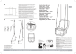
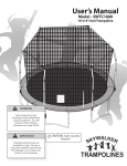
1.2.4 Mounting position
XLNT CyberHoist II™are versatile devices that could be positioned with motor up as well as with
motor down (optional). However, for XLNT CyberHoist II™, we only recommend the use of inverted
position (motor down), up to half speed. In all cases see to it that the chain bag is properly
positioned and chain flow not disturbed.
NORMAL
POSITION
INVERTED
POSITION
Figure 1: Mounting positions
!
WARNING!
To use XLNT Cyberhoist II™ in Inverted Position the optional available external chain
guide needs to be fitted on the upper corner above the chain bag. This is required to
assure a proper chain flow in to chain bag. Without this guide the chain may drop aside
of the bag which may have severe consequences in terms of damage of equipment or
even people underneath.
Page | 14
1.3 Operating
XLNT CyberHoist II™are multi-voltage and shall be powered via CyberMotion™ C-Power™ distro
and infra structure to 3-phase power supply within the range of between 200 and 440 V +/- 10%
at 50 or 60Hz at Ambient temperature: +5 up to +40°C.
When during transport or storage the equipment has been subject to lower temperatures than
+5°C, it is recommended to allow the equipment to acclimatize before to putting it in service.
!
WARNING!
Use of C-Power™ distro and corresponding infrastructure is compulsory to provide
system safety at SIL3 level. XLNT ™ cannot be liable for any E-Stop failures or other
consequences whenever alternative power arrangements have been used instead.
In order to operate a XLNT CyberHoist II™ it is necessary to connect one of the MotionCue3D
operating platforms: MotionCue3D performance desk, with the Ethernet port of the first hoist which
will act as the master. Additional hoists are to be connected either in daisy chain using the Realtime Ethernet ports, or in-star via an additional switch. For further details see the manual of the
operating system.
Moreover, for set-up and service purposes, XLNT CyberHoist II™could be operated as a standalone
using the dedicated handheld button box.
For further operating details see the MotionCue3D users manual.
Power (3 phase)
CAT 5 UTP
with Neutrik
EtherCON RJ45
XLNT
CyberHoist II™
XLNT MotionCue3D console
Local power
(single phase)
Figure 2: Typical set-up of an XLNT CyberMotion™ touring set with Performance console
Page | 15
1.4 Schematic system over view
Motor cable
Break
out 4Ch
CH 528 Chain
Hoist
CAT 5 UTP with Neutrik
EtherCON RJ45
Multi
cable
Power
distro 8 ch
(3 phase)
Local power
(single phase)
Local
power
(3
phase
)
MotionCue3D console
Figure 3: Typical set-up of an XLNT CyberMotion™ touring set with Performance console
Page | 16
Chapter 2: Technical description
2.1 Mechanical concept
The technical concept of both XLNT CyberHoist II™are alike and following assemblies could be
identified as per Figure 3 below.
F
D
A
H
B
A. Electric motor
B. Housing with gearbox and chain wheel
C. Chain guide with limits (bottom side)
D. Drive and Motion controller
E. Brakes
F. Integrated load cell axels
G. Chain bag
H. Absolute and incremental encoder
E
C
B
G
Figure 4: Assemblies
NOTE:
The hoist parameters are stored on a memory chip card that is part of the hoist
body. Whenever the drive (D) has to be replaced the data is automatically
loaded in to the new drive memory and tuned
!
!
WARNING!
Only qualified and trained technicians are allowed to dismantle and or replace
parts or assemblies
!.
Page | 17
2.2 Brakes
In the XLNT CyberHoist II™ concept, braking is achieved through electronic
speed regulation from and to through zero speed. Developed braking energy
during speed reduction, is fed back in to the power network using regenerative
power management. Therefore the mechanical brakes are to be considered as
holding brakes (brakes that do not implement friction work in regular
operation but merely secure a position reached). In case of an emergency,
however, it may also perform a braking function. In their standard design,
brakes of FDD series are generally “holding brakes” with emergency-stop
features
Operating time: 100%
Ambient temperature: -10 to +40°C
The electromagnetically released spring-pressure brakes of the FDD series are
fail-safe brakes.
This means that the braking torque is generated by means of spring force in
closed-loop operation and revoked by magnetic force.
Figure 5: Brakes
During braking, through the axially movable armature disk (item 2), the
incorporated pressure springs (item 4, Illustration 1) press the rotor (item 3)
which is radial positively connected with the machine shaft against the
counter-friction surface (intermediate flange (item 8), friction plate (item 7) or
motor flange). The two-sided friction, between the linings of the rotor and the
armature disk and/or the counter-friction surface, produces the braking
torque.
During release, a magnetic force is produced through applying a direct voltage
at the magnet body (item 1) via the field winding. This magnetic force draws
the armature disk (item 2) to the magnetic body and the brake rotor is
released.
Figure 6: Brakes section
Owing to design, braking and releasing operation take place in a technically separated manner with
the two mechanically connected individual brakes (brake 1, brake 2, This is why braking operation
is safeguarded even if one brake completely fails (redundant system).
During manual releasing, the armature disks are mechanically pulled against the magnet bodies by
slewing the manual releasing brackets (item 5, with screwed-in manual releasing lever (item 5.1))
and thus the rotors are released. This enables you to release the brake, for example, even if there
is a power failure.
Page | 18
2.2.1 Maintenance
The spring-applied brake is nearly maintenance-free. However, when the maximum air gap
(maximum: 0.4 +0.15 mm) is reached, a readjustment (new adjustment) of the air gap a will be
required for a safe functioning and operation of the brake. Keep the brake clean and dry and free
of any contaminants such as dust, grease etc.
Readjusting the air gap:
!
Viewing in direction of the brake (see illustration on right)
loosen the three fastening screws (item 11) by turning
them half a rotation counter-clockwise.
Turn the hollow screws (item 12) into the magnet body by
also turning them counter clockwise.
Turn the fastening screws (item 11) (clockwise) into the
(motor) flange until the nominal air gap (to be measured
with feeling gauges 0.35mm) exists
at three positions on the circumference.
Reset the hollow screws (item 12), i.e. turn them out of the magnet body (clockwise) until
a firm contact with the counter-friction surface is reached.
Tighten the fastening screws (item 11) with the tightening torque 25 Nm.
Subsequently control the air gap between housing (item 1) and armature disk (item 2), if
necessary, carry out a readjustment
WARNING!
The brake should be tested after each air gap correction. See 8.4 Periodical
inspection on how to proceed
2.3 Chain
The chain is the most essential and at the same time most vulnerable component of the hoist. It
has been selected in accordance to its duty. Only use chains that are certified and fully compliant
to the specifications below.
The lifetime and thus the safe working period of a chain depends on the maintenance discipline.
NOTE:
Keep the chain clean and slightly lubricated at all times.
NOTE:
The “slack fall chain stop” is a safety component, not a functional one. Keep
sufficient distance between stop and hoist body at all times and avoid collision
!
!
!
WARNING!
The end of the chain is provided with a chain stopper, this is a safety
component. The stop is fitted at about 60 cm from the chain end to lead the
chain in to the chain bucket in a proper way. The chain end must be securely
fitted on the chain end fitting located at the hoist body
!.
Page | 19
2.3.1 Chain specifications
CyberHoist II
500 kg - 0.5 t
Lift chain
Standard
Size
7 x 21 mm
Class
DAT
Quality
RTS
Diameter (D)
7.0 +0.1/-0.3 mm
Pitch (t)
21.0 +0.3/-0.15 mm
Control length (11xt)
231.0 +0.7/-0.4 mm
Diameter (D2)
Maximum breaking stress
max. 7.5 mm
800 N/mm²
Hardened surface
580 or 700 HV
Hardening depth
0.04 d +/- 0.01d
Breaking load
Total breaking elongation
Hardened surface
Nominal working load, 1 fall
61,6 kN
>10% min.
500 - 650 HV 10
1000 kg / 1 t
Maximum working stress
125 N/mm²
Maximum working load at
Fem 2m
980 kg
Surface harding thickness
0.28 to 0.07 mm
Standard
Weignt per meter
EN 818-7
1.06 kg
Table 2: Chain specifications
Figure 7: Chain specifications
Page | 20
2.3.1.1 Measuring wear on the chain
The chain must be replaced if the average wire diameter D has been reduced due to wear by more
than 10% of the nominal thickness at some point on the chain link.
The average wire diameter dm = (d1 + d2):2 <= 0.9d, whereby the average wire diameter dm is
calculated from two individual values d1 and d2 measured rotated through 90° with respect to
each other.
Figure 8: Measuring wear on the chain
The chain must be replaced if a single chain link is permanently expanded or if the inner pitch t of
the individual link has increased in size by more than 5% as a result of wear. The chain must also
be replaced if the inner pitch 11t has increased in size by more than 2% along a measuring section
of 11 chain links.
!
NOTE:
As the information above shows, one should take into account that, although
tolerances are still within the manufacturer’s specification, elongation of the
chain inherent to use may cause differences in chain length. As a consequence,
system repetitive accuracy among two or more hoists may not be achievable
under all circumstances. The effective difference in chain length is not
necessarily proportional to the total chain length. Correction on excessive
differences is limited, so contact the XLNT CyberMotion service centre in your
area for possible options
Page | 21
2.3.1.2 Chain replacement
Whennever chain needs to be replaced, either due to damage, wear or incase a longer lift is
requirred, it is essential to follow the replacement procedure as described hereunder.
!
NOTE:
Chain of the Cyberhoist II hoist cannot removed nor inserted manually with use
of the yellow pickle.
For such operation the use of the operating console is a necessity.
Replacement procedures via the console require special authorization to open
the Maintenance section in the Support mode of the software.
Removal preparations by authorized person only:
a.
b.
c.
d.
e.
f.
g.
!
Connect the hoist with the desk
Position the hook at 1 meter from the hoist body
Remove the hook (see section 2.4.1.2) and the compression spring
Remove the chain bag and place it under the hoist
Release the slack end of the chain from it’s fitting
Remove the chain stopper and the spring
Run the hoist carefully upwards at slow speed until the chain fully falls down in the bag.
Avoid the chain to touch the work floor this to protect it against dust and dirt.
Slack chain
end fitting
WARNING!
The replacement of a chain should be done by an authorized technician only.
Besides the authorization to enter the Maintenance section, it also requires a
special tool to enter the chain.
Entering chain without this tool may damage the internal chain guides with
substantial repair costs as a consequences.
Fitting of a new chain by authorized person only:
a.
b.
c.
d.
e.
Prepare the new chain at correct length
Position the special plastic chain insertion tool at the slack chain side of the hoist body
and start the motion down at lowest possible speed until you feel the chain tool is taken by
the chain wheel.
Place the first link of the chain over hook at the end of the chain tool with the link weld to
the outside.
Follow the instructions on the display of the console
Place the compression spring over the chain and mount the hook (see section 2.4.1.2)
.
!
WARNING!
This action must be undertaken by an authorized and competent person only.
The authorization includes aces to the maintenance mode on the operating desk
that will guide the person step by step through the procedure to follow.
Page | 22
f.
g.
h.
i.
j.
k.
!
See to it that the locking pins are securely mounted
Run the chain through the hoist following the instructions on the display
Mount the chain stopper with its buffer spring at approx. 50 cm from the chain end
Fit the slack chain end without any twists on the clamp at the hoist body and mount the
chain bag.
Continue to follow the instructions on the display
When the procedure is completed, the hoist is ready for use.
.
NOTE:
Don’t run the hoist when there is no chain inside as it will disturb the absolute
encoder position in relation to the hook. Should this happen, contact the XLNT
CyberMotion™ service centre in your area to reposition the encoder
L = 500 for small chain bag 25m chain
L = 720 for large chain bag 40m chain
Page | 23
2.4 Hook
The hook, a safety hook, has been selected in accordance to its duty and functionality. Never use
hooks other than traceable, certified ones fully compliant to the specifications below.
NOTE:
!
Keep the hook clean and properly maintained at all times. For further
instructions see Chapter 8: Maintenance and inspection
2.4.1 Hook specifications
CyberHoist II
500 kg - 0,5 t
Hook
Standard
Type
XLBA1R
Hook opening (c )
43.8 mm
Thickness (d)
Width outside (g)
23 mm
90,5 mm
Width (e)
27,5 mm
For chain
7 - 8 mm
Maximum working stress
800 N/mm²
Breaking load
80 kN
Total breaking
elongation
16%
Working load limit
Minimum breaking stress
Maximum working load
at FEM 1 bm
Standard
Weight
2,000 kg / 2 t
933 N/mm²
2,000 kg
EN 1677-3
1.5 kg
Table 3: Hook specifications
2.4.1.1 Measuring wear on the Hook
The hook must be replaced if the average width (e) has been reduced due to wear by more than
10% of the nominal thickness, or if the hook opening (c) has increased by more than 15 %.
The hook must be replaced if free and easy rotation of the hook towards the upper section is no
longer possible.
Page | 24
2.4.1.2 Hook replacement - 1 fall hooks
WARNING!
!
This action must be undertaken by an authorized and competent person only.
a.
b.
c.
d.
e.
f.
Connect the yellow pickle for manual operations, follow the procedure as described at
section 6.4
Lower the hook and remove the load if any
Run the hoist until the hook is about 1meter from the hoist body
Use a matching pin to drive both safety pins out and remove the load pin
Position the new hook and enter the load pin (a), this pin fits in only one manner, related
to the shape of the chain shackle. Never use force to enter the pin (b) !!
Position and drive the two security pin’s in position. Beware on one side the pin fits only in
one manner, never use force to get it in (c).
a
b
c
Figure 10: Fixing the hook in three steps
Figure 13: complete hook assembly
Page | 25
Chapter 3: Functioning
The purpose of a XLNT CyberHoist II™system is to dynamically move objects in a predefined
space.
The setting in which the system will normally be used is show related (e.g. concerts, theatre
shows, television shows etc.) in spaces such as stadiums, theatres, outdoor venues etc.
An “object” can be any 3D construction, varying from, for example, a projection screen to a
complete moving stage or platform. Object characteristics are only known to the user. Users can be
but are not limited to rental companies, theatres etc. The manufacturer is unaware of form, mass
and other characteristics of an object and cannot be held liable to any actions whatsoever related
to the programming or construction of an object (or any other type of related activity).
In order to avoid accidents the operator must always clearly define that roll and pitch are to be
excluded. If he doesn’t, the system will validate such action whenever the operator mistakenly
programs a roll or pitch.
Objects are moved by high-precision computer-controlled “intelligent” actuators such as
XLNT CyberHoist II™. These actuators are “aware” of their role in the movement of an object
through the use of a software model which runs inside each actuator. Also,
they are “aware” of other actuators operating within the same object.
Trough the software model, objects are “aware” of their position in the
predefined space.
Programming the movement of objects is realized through the use of
dedicated software (MotionCue3D) in which the complete 3D movement of
objects is programmed and commands are sent to the objects. The
computers in the actuators receive the object’s 3D commands and
transform these to the necessary movement of the actuators.
An object can consist of multiple sub-objects which together form one large
object e.g. the body of a bird (the object) with separate movable wings
(the sub-objects) An actuator is only controlled directly during start-up,
load-in/load-out and in case of maintenance. For these purposes a handheld
operating tool is available that can be connected straight in to the drive unit.
!
Figure 7 Object
WARNING!
Manual operations by means of the yellow pickle, must be undertaken by a
competent person only.
In this mode, the system doesn’t consider the relative Up/Down positions, the
under load detection nor the synchronism among actuators. Pickle mode
therefore should be used for individual hoist only.
Page | 26
Chapter 4: Safety
4.1 Risk assessment
The user must make a risk assessment, based on all plans drawn up for the particular show to
establish actuators. The result of this assessment is the guideline for the selection of matching
actuators and must reflect the manufacturer’s specifications. Although other parties involved might
focus on other topics, the user of the XLNT CyberHoist II™must use his rigging plan as a basis for
his part of the risk assessment. International standards as well as local laws and regulations must
be compiled within the process of the risk assessment.
4.2 Outdoor use
As stated in Chapter 1: Introduction, the XLNT CyberHoist II™are not intended for unprotected
outdoor use. However, if the user decides to take the responsibility and accepts the consequences
of outdoor use, the following information and directions may help to avoid malfunction.
!
NOTE:
his information and guidance is not extensive, and certainly not enough to
have all risks covered. Unprotected outdoor use is the user’s own responsibility
and at the user’s own risk, including any cause of events resulting from
mechanical or electrical malfunctioning or breakdown of one or more XLNT
CyberHoist II™ or a combination of equipment which includes one or more of
these.
Heat radiation:
XLNT CyberHoist II™ and attached electronics produce heat that is radiated to the environment by
means of its surface.
!
NOTE:
Do not block the natural air flow around the XLNT CyberHoist II™ and never
put a protective (tight) cover around the hoist to protect it from rain etc. Never
place heat sources like fan exhausts, heaters or luminaries etc. in the vicinity of
a XLNT CyberHoist II™. The unit will overheat and shut itself down!
4.3 Lifting persons and flying performers
As stated in 1.2.2 Lifting persons and performer flying, XLNT CyberHoist II™ are designed to use
for lifting persons or flying performers. However the following information and directions may help
to avoid unwanted incidents.
!
NOTE:
This information and guidance is not extensive, and certainly not enough to
have all risks covered. Flying of persons or performer flying is completely the
user’s own responsibility and at his/her own risk.
As stated in 4.1 Risk assessment, a risk assessment must be made for every event or show. When
lifting persons or flying performers, special attention must be given to:
Page | 27
risks related to the persons or performers being moved
risks related to the equipment used to do so
fall protection that might be used
possibilities of evacuation of the persons or performers that are lifted or flown in case of
emergency, malfunctioning of equipment etc.
providing information about these persons or performers to emergency services, and
possibly laying down a protocol with these services in case of emergency
providing adequate means of communication with emergency instructions
4.4 Risks due to the scenic movements
Scenic movements generate extra hazards, e.g. during shows. This probably means they occur in
low light situations, where the user’s view is blocked by scenery or blinded by lights. The risk
assessment must elaborate on how to deal with hazards that may arise in a particular show.
The user must have visual contact at all times with all objects. Continuous visual contact may be
accomplished by the user alone, or with “spotting colleagues” at different corners of the stage, and
by staying in contact with each other, possibly with an emergency stop or Dead Man’s Handle in
their hand. Infrared camera’s can also help the user to maintain visual contact with the moving
objects.
4.5 Power down when not in use
Only competent persons, such as those described in 1.3 Operating, are permitted to operate
XLNT CyberHoist II™. To prevent unauthorized operation, when not in use or in the operator’s
absence:
the hoists must be ”de-initialized” or be cut off from their power source.
4.6 Risk due to dynamic effects
Acceleration, deceleration, use of E-stop or Dead Man’s Handle, manipulations that create a
changeover of gravity point or swing etc. are all elements that may generate dynamics in the
system. The structure above, from which actuators are suspended, usually trusses, may contribute
to this phenomena due to their flexibility.
Particularly in cases of concentrated point load patterns as well as in cases of heavy loads, dynamic
effects generated by multiple actuators should be taken in to account when evaluating the impact
of all individual lifting points as well as the combined impact effects on the structure above.
Page | 28
Chapter 5: Storage, transport and reception
5.1 General handling
To avoid damage to the interior electronics, handle XLNT CyberHoist II™ with care and always
travel flight cases on wheels. Never stack more than two flight cases with
XLNT CyberHoist II™ on top of each other.
!
WARNING!
A full flight case weights up to 160 kg (320 lbs). It is therefore preferable to
use a forklift to stack and un-stack the cases. In case you need to do this
often, call in enough colleagues; pay attention to your body position while
lifting and lowering (straight back, bend your knees etc.) to avoid serious injury
to your back. Wear safety shoes to avoid injuring your feet by the flight case.
Wear gloves to avoid injuries to your hands.
5.2 Storage
XLNT CyberHoist II™ can be stored in the cases supplied by the manufacturer. For regular storage
and for transport the following conditions must be maintained:
Temperature: between +5 to 40 º C / +41 to 104 ºF.
Humidity: between 10 - 70%, the environment may not be subject to condensation.
Dust: as long as your XLNT CyberHoist II™ is properly packed in e.g. a flight case, there
are no special conditions concerning dust. For long term storage, see Chapter 8:
Maintenance and inspection.
5.3 Transport
Avoid transportation of XLNT CyberHoist II™ in other means in flight cases and positioned on it’s
wheels. The flight cases should preferably not being “tipped”. It is advised to us original flight cases
from your XLNT dealer.
For transport conditions, see 5.2 Storage.
5.4 Reception
When receiving a newly purchased XLNT CyberHoist II™, the user must carry out the following,
prior to first use:
Inspect the product on the exterior for possible damage caused during transportation. In case
there is any damage, immediately contact your XLNT dealer.
Inspect the type label on the XLNT CyberHoist II™ for:
Correct type of hoist
If the adapted power supply fits in the range between 200 and 440 V +/- 10% at 50 or
60Hz
Register the following in your logbooks for every XLNT CyberHoist II™:
Date of first use,
Type
The serial number that is stated on the type label on the
XLNT CyberHoist II™
5.5 Included items
In the box you received from your XLNT dealer you should find the following items:
XLNT CyberHoist II™
XLNT CyberHoist II™ user manual (this manual)
Declaration of conformity (II-A) by XLNT, included in this manual
In case a manual is missing, you can download it at www.xlnt.com, or file a request at your local
XLNT dealer. Mention the serial number(s) of the hoist(s) involved in all correspondence.
Page | 29
Chapter 6: Installation and dismantling
6.1 Mounting:
!
NOTE:
All equipment and cables must be subject to a visual inspection before
installation, in order to avoid problems later on! See Chapter 8: Maintenance
and inspection.
In the procedure described here, we assume you have already provided for the proper rigging and
fixing of the hoists and that you are ready to take them out of their flight cases and install them. In
these instructions the term ‘main grid’ is used as analogy. It generally refers to ‘supporting
construction’ on which or in which the hoists are suspended.
Please make yourself familiar with the specific information provided with the XLNT products, before
you install and use them.
The easiest way of installing XLNT CyberHoist II™ is by suspending it from the main grid truss
structure.
!
WARNING!
!
WARNING!
Beware the chain bag is hanging free straight under the hoist in it’s natural
position at all times. It may not be obstructed in any form or way. This
otherwise may obstruct the chain flow in or out the bag. As such it may cause
the chain to fall out of the chain bag un wanted, or create knots in the bag.
Bots events may result in severe damage of the hoist and / or cause injuries or
fatalities among people underneath..
Beware the chain under no condition does touch the chain bag, any object, or
structural element.
a.
b.
c.
d.
e.
f.
g.
Mount the XLNT CyberHoist II™ on or integrate it in the main grid.
Put the power distribution cabinet (‘distro’) in place. Always ensure that you are able to
reach it easily in case of emergency or technical problems.
Power the XLNT CyberHoist II™ by using a break-out connected with the corresponding
power distro. Only use power cables of sufficient sections and respect the maximum cable
length as indicated.
Attach the safety cable of the break-out to your main-grid, if applicable.
Connect the power break-outs and, if applicable, the distro. Only use power cables of
sufficient sections and respect the maximum cable length as indicated.
With a suitable instrument, check the supplied power at your location: single phase as well
as 3-phase power supply. For specifications and tolerances, see Annex 1. In case the
supply voltage is not what it should be, contact the local responsible person, and wait
before switching on the equipment until the correct voltage has been provided.
Connect the distro to the local power supply. Use only power cables of sufficient sections
and respect the maximum cable length as indicated.
Page | 30
!
h.
i.
XLNT CyberHoist II™ have a SIL3 network controlled Emergency-Stop circuit
that, in case of activation, brings the hoist in to a safe state internally. In
addition, the power distribution has a hard wired E-stop system provision. For
custom solutions, contact your XLNT dealer for information
Install additional Emergency-Stop switches if your Risk Assessment concludes that this is
necessary.
Connect the Ethercon data cable coming from the operating console with the corresponding
Ethernet port on the XLNT CyberHoist II™ . In case of multiple hoists, RT Ethernet data
ports of the individual hoists are to be daisy linked.
!
NOTE:
!
NOTE:
.
NOTE:
For large groups of hoists it is recommended to split the system in different
domains. See the system operating / software manual for details.
Only use CAT 5, CAT 5e or CAT 6 cabling
For distances up to 50m: use STP. FTP or SFTP
For distances from 50 - 95 m: use UTP cable
TIP:
While connecting cables to the your equipment in the main grid, always keep an
extra 1.5 m length at both ends, so that you can move the equipment a little
without having to redo the cabling
Power connector
Ethercon data connector
Figure 12: Connectors
!
WARNING!
To avoid getting caught by the moving objects, electric cables should have
enough slack, but not too much. Always tape the cabling alongside your slings,
to prevent the cable from being pulled or torn connections in cabling, as they
may loosen during use.
6.2 Powering up the system
When all abovementioned actions have been completed, the power supply is in place and E-stop
station’s wired, you can power up your system:
Switch on the main power
Check if additional data switches have power, either by the Ethercon cabling, or by a
separate power cable. See “XLNT Data Motion User Manual” for explanation of all LED
indicators.
Page | 31
You are now ready to use and control the hoists by using the console. For operating
instructions and use of the MotionCue3D software, we refer to the XLNT MotionCue3D
manuals.
Page | 32
6.3 Procedure for un-mounting
The following procedure describes the most convenient way of un-mounting an
XLNT CyberHoist II™, and packing it for transport and later use:
a. In manual mode, run the hook until its highest position (from the operating desk or by
means of the handheld connected to the hoist).
b. Shut off the power to the hoists Disconnect the network cable and the power cable from
the hoist.
c. Lower the hoist in the most convenient way and position it over its flight case.
d. Gently place each hoist into its flight case using of a secondary lifting device.
e. Close the flight case.
!
NOTE:
Never stack more than two flight cases on top of each other, to avoid tumbling
down!
Always transport XLNT CyberHoist II™ cases ‘on wheels’: tipping or turning
over the cases is not recommended!
6.4 Manual operations with pickle
The motion controller recognizes two input states, network mode and pickle mode.
Selection of the mode is achieved automatically after a power cycle and connecting network or
pickle. A power cycle is achieved by means of main power reset or disconnect /connect power plug
on the hoist).
Each change from one mode to the other, a new power cycle is compulsory. Execute the procedure
with network or pickle disconnected.
Pickle mode procedure:
1. Disconnect the network cable
2. Make a power cycle, (power Off/On) wait until LED’s turn WHITE
3. Connect the pickle with E-stop button pulled out (turn and pull) and wait until LED’s turn
RED
4. Push the E-stop button In and wait until LED’s turn BLUE
5. Pull the E-stop button out, LED’s start to blink BLUE
6. Hoist is ready for use once the blinking in BLUE stops
7. Push the arrow button ↑ to go UP, LED’s turn GREEN for as long as the motion goes
8. Push the arrow button ↓ to go Down, LED’s turn RED for as long as the motion goes
After about 30 minutes of no action, the hoist will turn in the Power-Off mode. Proceed from 2) to
activate the pickle again.
!
NOTE:
If an hoist is already in the pickle mode, proceed from 3) to activate the pickle
again.
Page | 33
Chapter 7: Operating Conditions
As stated in Chapter 1: Introduction, XLNT CyberHoist II™ can be operated with a dedicated
operating desk from the XLNT CyberMotion™ family running the XLNT MotionCue3D™ software or
directly by means of a handheld plugged into the corresponding receptacle at the CyberHoist II™.
Environmental conditions for operation
The following conditions must be met when operating XLNT CyberHoist II™
Temperature:
Humidity:
Dust:
+5 - 40 ºC / 41 - 104 ºF
10 - 90 %, in a non-condensing environment
Avoid dusty environments: due to the forced cooling, dust is sucked into the inlet.
Although the inlet is equipped with a filter, dust will get into the cabinet itself and will stick around
fans and parts on the inside, preventing it from cooling properly.
Condensation
After powering down the XLNT CyberHoist II™ they can be packed in their cases immediately.
When transporting a XLNT CyberHoist II™, always use a closed flight case on wheels.
!
NOTE:
When condensation has formed after powering down, e.g. during the night in
between concerts, wait before powering up the hoists until condensation has
evaporated.
Page | 34
Chapter 8: Maintenance and inspection
8.1 Prior to each use
The user must visually inspect the XLNT CyberHoist II™ prior to each use for defects, wear and
tear and irregularities, and if needed take action. The term “each use” is defined as “each time a
XLNT CyberHoist II™ is installed for one show, or consequent shows at one and the same location
without altering the set-up of the hoists”.
The following points are important:
Absence of the type label on the housing of the XLNT CyberHoist II™: when damaged or
absent one should contact the XLNT service point for immediate replacement. Proper
identification is a must before putting the device into service.
Wear, tear and damage to the rope or rope outlets: this usually forecasts damage to the
rope or pulley wheels.
Wear, tear and damage to the rope when checking visually: if in any doubt, call in a
competent person who can check if the rope ability to perform safely has been
compromised; see specifications in the XLNT CyberHoist II™ Maintenance Manual.
Damage to the housing: this indicates possible damage to the interior
Suspension shackle, hoist attachment point: on damage, bending and presence of safety
pin.
Load-cell axels should be fastened, though freely movable; check for damages. Damaging
a load-cell will almost always give it an offset.
Check the connectors of your power cable for damage, and check the locking mechanism
for correct functioning.
Check the cable glands at the connector and the housing. These should be tight and the
insulation should not have come out.
Check hardware limit switches.
!
!
NOTE:
Only authorized service personnel are allowed to do repairs on the XLNT
CyberHoist II™. Repairs must be logged.
WARNING!
The speed at which a XLNT CyberHoist II™ can run, in combination with the
fact that luminaries in the vicinity might heat up the chain, may cause the
lubrication to evaporate quickly. Too little or no lubrication causes excessive
wear and tear of the chain. This can cause the chain to jam or even lead to
failure. Any one or a combination of these factors may cause the load to fall
down or collapse, at the risk of causing severe injury or damage to property
8.2 After frequent use or use under special circumstances
When a XLNT CyberHoist II™ is frequently used, e.g. because it’s used a lot during a long show
period, or when it’s been used under especially harsh conditions, e.g. near salt water, it must be
inspected by a competent XLNT service technician.
Page | 35
8.3 During long periods of use
When the hoists are used frequently over a longer period, a regular visual inspection by a
competent person is necessary. Attention must be given to the following:
Tightening of the bolted connections.
Hook condition and their ability to rotate (see 2.4.1.1 Measuring wear on the Hook).
Chain condition, lubrication and eventual wear (see 2.3.1.1 Measuring wear on the chain).
Cabling on proper taping, slack etc.
Connectors, their locking mechanisms, insulation, etc.
If a system with some hoists is used for a long period of time, e.g. when touring for a period longer
than two months, it is necessary to plan some inspections during this period. The user must take
care to stipulate a proper maintenance plan.
8.4 Periodical inspection
XLNT CyberHoist II™ maybe inspected and tested by competent XLNT service personnel only.
Inspection intervals must be executed in accordance with local laws and regulations, but are not to
exceed a maximum of 12 months between inspections. The findings of these inspections must be
logged.
Points of inspection and terms are:
Action
1
2
3
4
5
6
7
8
9
10
11
12
13
14
Table
Normal brake operations
General inspection of the chain
General inspection of the hook
Over load and under load values
Detailed inspection , cleaning and lubrication of
the chain
Detailed inspection , cleaning and lubrication of
the hook
Over load triggering point
Measuring wear on the chain, see criteria
Measuring wear on the hooks, see criteria
Checking of the screw tightening torques and
checking for signs of damage mall function and
corrosion
Normal brake operations
General inspection of the chain
General inspection of the hook
Over load and under load values
4: Points of inspection
Interval min. once
per year
Daily
Daily
Daily
Daily
After each job
Qualification of
personnel
Operator
Operator
Operator
Operator
Qualified mechanic
After each job
Qualified mechanic
Annually
Qualified mechanic +
Operator
Qualified mechanic
Qualified mechanic
Qualified mechanic
Annually
Annually
Annually
Annually
Annually
Annually
See indicator
Qualified mechanic +
Operator
Qualified mechanic
Qualified mechanic
Manufacturer
Service information with respect to above table:
1. The operator should be permanently aware of any abnormal noises or load behaviour when
reaching Zero speed.
2. Chain must be clean and well lubricated at all times.
3. The hook must be able to rotate easily and open / close without any enforcement.
4. Operator should watch over the monitored load values.
5. Thorough visual inspection of the chain. Chain should look polished on all contact points, no
severe surface damage of any kind may be observed.
6. Hook must be in good condition, no severe surface damage of any kind may be observed.
7. The correct trigger point of the load cell must be checked against a known load at 110% of
the rated load. For renewed calibration consult a qualified operator.
8. Apply points 2) and 5). Check for deformations and wear. For acceptance criteria of the
chain; see 2.3.1.1 Measuring wear on the chain.
9. Apply points 3) and 6). Check for deformations and wear. For acceptance criteria of the
hook; see 2.4.1.1 Measuring wear on the Hook.
Page | 36
10. Check all bolt connections, condition of internal and external wiring and general
appearance.
11. Check mechanical brake function of both brakes individually. For brake selection, and
testing consult the qualified operator with access to the maintenance mode on the
operating desk, which is required to apply this service.
Dynamic test:
apply test load of 110% go up and down at moderate speed and apply an E-stop.
Load should come to a standstill within an acceptable distance.
Static test:
apply a static load of 125%, brake should not give any sign of slippage.
If slippage occurs, see Chapter 2.2.1 how to check and correct the brake air gap.
After each correction, both tests must be repeated.
12. Check Over travel limits adjustment:
For over travel limits testing consult the qualified operator with access to the maintenance
mode on the operating desk, which is required to apply this service.
!
Select down and run the hook downwards until the buffer spring on the end stopper
gently touches de chain guide. It should stop as soon as the spring intends to
build-up pressure. Turning the adjustment nut close to the spring, clockwise will
make the switch act sooner and turning the nut anti-clockwise will make it act
later.
The precise moment of switching could be noticed by listening to the clicking of the
micro switch. Repeat the action if
needed until the switch act in due
time, means at minimum
compression of the spring.
Select Up to run the hoist in the
opposite direction until the buffer
spring on top of the hook gently
touches de chain guide. It should
stop as soon as the spring intends
Adjustment
to build-up pressure. Turning the
nuts
adjustment nut close to the spring,
clockwise will make the switch act
Figure 8 Adjustment nuts
sooner and turning the nut anticlockwise will make it act later.
The precise moment of switching could be noticed by listening to the clicking of the
micro switch. Repeat the action if needed until the switch act in due time, means at
minimum compression of the spring.
NOTE:
the chain guide is fitted on pressure springs, this to enable it to trigger the
safety switches behind it. It therefore is important to follow the instructions of
limit switch adjustments made by the two nuts that are holding the chain
guide.
Only authorized service personnel are allowed to do repairs on the XLNT
CyberHoist II™. Repairs must be logged.
Page | 37
8.5 Safe working period
XLNT CyberHoist II™ are optionally equipped with an operating and event monitor system that
stores all data relevant on the chip that is part of the hoist body. The remaining service period until
the general overhaul is calculated from the registered values. The outcome in remaining service
hours or travel distance is listed in the parameter file. See operating manual.
Once the indicator shows a remaining elapse time of less than 5%, a warning will be given. When
reaching the full period, the hoist must be returned to the manufacturer or his delegate for general
overhaul and determination of a second SWP.
8.6 Long term storage
When you want to store your XLNT CyberHoist II™ for a long period, the following procedure must
be followed:
Make an entry in your maintenance logs when you take them out of service.
During the storage period no inspections are necessary.
During storage the environmental condition set in Chapter 5: Storage, transport and
reception must be maintained.
When putting the hoist into service again, an inspection and a test must be done by a
competent XLNT serviceman. Findings of these inspections must be logged.
Page | 38
Chapter 9: Decommissioning
If case the equipment is taken out of service, e.g. because the product has reached its end of
(economical) life, is damaged beyond repair or for any other reason, it must be sent back to your
local supplier. They can take care of dismantling the item in an environmentally friendly manner.
The hoist can also be offered to a company specialized in dismantling and recycling this type of
electronic equipment.
!
WARNING
Never dump your equipment: XLNT CyberHoist II™ contain electrical parts and
lubrication greases that are not environmentally friendly, and need special
treatment in order to dispose of them in an environmentally safe way!
Page | 39
Chapter 10: List of hazards
No. Hazards
1
Mechanical hazards due to:
a) shape
b) relative location
c) mass and stability (potential energy of elements which may shift under
effect of gravity )
d) mass and velocity (kinetic energy of elements in controlled or
uncontrolled motion)
e) inadequacy of mechanical strength of components
f) elastic elements
g) liquid and gasses
h) effects of vacuum
1.1
Crushing hazard
1.2
1.3
Shearing hazard
Cutting or severing hazard
1.4
Entanglement hazard
1.5
1.6
1.7
1.8
1.9
2
2.1
Drawing-in or trapping hazard
Impact hazard
Stabbing or puncture hazard
Friction or abrasion hazard
High pressure fluid injection or ejection hazard
Electric hazards due to:
Contact of persons with live parts (direct contact)
Contact of persons with parts which become live under faulty conditions
(indirect contact)
Approach to live parts under high voltage
Electrostatic phenomena
Thermal radiation
Thermal hazards, resulting in
Burns, scalds and other injuries by a possible contact of persons with the
object or materials with extreme high or low temperature
Damage to health by hot or cold working environment
Hazards generated by noise, resulting in
Hearing loss (deafness) or other physiological disorder
Interference with speed communication, acoustic signals etc.
Hazards generated by vibrations
Use of handheld machines
Whole body vibrations
Hazards generated by radiation
Low frequencies, radio frequency radiation, micro waves
Infrared, visible and ultraviolet light
X and gamma rays
Alpha, beta rays, electron or ion beams, neutrons
Laser
2.2
2.3
2.4
2.5
3
3.1
3.2
4
4.1
4.2
5
5.1
5.2
6
6.1
6.2
6.3
6.4
6.5
Events, recommendation and
references to relevant chapters
of this document
NA
Apply local code of rigging practice
x
controlled by drive / SAS requirement
compliance to DIN56950 / BGV-C1
spring
NA
NA
chain while load in motion - chain
sliders if applied - spring on hook
while in upper position - chain falling
from chain bag - Ch. 6
NA
NA
knots in chain / due to use of chain
sliders - Ch. 2.3 - 2.3.1.2 - 6
NA
NA
NA
NA
NA
See C-Power users manual
See C-Power users manual
NA
NA
Ch. 4.2
NA
NA
NA
NA
NA
NA
NA
NA
NA
NA
NA
Page | 40
Events, recommendation and
references to relevant chapters
of this document
No. Hazards
7
7.1
7.2
7.3
8
8.1
8.2
8.3
8.4
8.5
8.6
8.7
8.8
9
10
10.1
10.2
10.3
10.4
10.5
10.6
Hazards generated by material and substances processes or used by the
machinery
Hazards from contact with or inhalation of harmfull fluids, gases, fumes
and dusts
Fire or explosion hazard
Biologic or micro biological hazards
Hazards geberated by neglected ergonomic principals
Unhelthy postures or excessive effort
Inadequate considerations of hand-arm or foot anatomy
Neglected use of personal protection equipment
Inadequate local lighting
Mental overload and underload stress
Human error, human behavior
Inadequate design, location of manual controls
Inadequate design or location of display's
Combination of hazards
Unexpected start-up, overrun / overspeed or any mal function
Failure / disorder of the control system
Restoration of energy supply after an interruption
External influences on electrical equipment
Other external influences, gravity, wind
Erros in software
Erorrs made by the operator (see also 8.6)
11
Impossebility of stopping the machine in the best possible condition
12
13
14
15
16
17
18
19
Variations in the rotational speeds of tool
Failure of power supply
faillure of the control circuit
Errors of lifting
Break-up during operation
Falling or ejected objects or fluids
Loss of stability / overturning
Slip, trip and fall of persons
Ch. 2.2 - 8.4
NA
NA
N
self weight Ch. 1.1
NA
aplicable rigging code of practis
NA
See MotionCue users manual
See MotionCue users manual
NA
NA
See Motion System requirements
See Motion System requirements
manual action requirred
See Motion System requirements
Ch. 4.2
See Motion System requirements
See Motion System requirements
Ch. 6.4 - see also C-Power user
manual
NA
See Motion System requirements
See Motion System requirements
Ch. 6.1 - adressed at training
See Motion System requirements
Ch. 2.3
NA
NA
Additional hazards, hazourdous situations and hazardous events due to mobility
20
20.1
20.2
20.3
20.4
20.5
Relating to the travelling function
Movement when starting the engine
Movement without a driver at the drivers position
Movement without all parts in a safe position
Exsessive speed of pedestrian controlled machinery
Exsessive ossiclationwhen moving
NA
NA
NA
NA
NA
NA
20.6
Insufficient ability of machniery to be slowed down, stopped and
imobilised
NA
Page | 41
No. Hazards
21
Linked to the work position on the machine
21.1 Fall of persons during access to the work position
21.2 Exhasut gassses/lack of oxigen at work position
21.3 Fire
21.4 Mechanical hazards at work position
21.5
21.6
21.7
21.8
21.9
21.10
22
22.1
22.2
23
24
24.1
24.2
24.3
25
25.1
25.2
25.3
26
27
27.1
27.1.1
27.1.2
27.1.3
27.1.4
27.1.5
27.2
27.3
27.4
27.5
27.6
27.7
27.8
27.9
Events, recommendation and
references to relevant chapters
of this document
Insufficient visibility from the work position
Inadequate lighting
Inadequate seatig
Noise at work position
Vibration at work position
Insuficient means of evacuation
Due to controle system
Inadequate location of manual controls
Inadequate design of manual controls and mode of operation
From handling the machine
Due to powersource and transmission of power
Hazards from the engine and the bateries
Hazards of transmission of power between the machines
Hazards from coupoing towing
From/to third persons
Unauthirised start-up or use
Drift of aprt away from its stopping position
Lack of inadequacy of visiual or acoustic warning means
aplicable rigging code of practis and
adressed at training
NA
NA
aplicable rigging code of practis
andadressed at training
adressed at training
NA
NA
adressed at training
NA
aplicable rigging code of practis
Ch. 6.4
Ch. 6.4
NA
NA - the machine is multy voltage
See C-Power users manual
NA
NA
protected by user ID password
See Motion System requirements
NA
see MotionCue operating manual Insufficient instructions for the driver / operator
adressed at training
Additional hazards, hazourdous situations and hazardous events due to lifting
Mechanical hazards and hazards events
adressed at training
From load falls, collisions, machine tipping caused by:B103
adressed at training
Lack of stability
adressed at training
Uncontrolled loading, overloading, overtuning moments exeeded
See Motion System requirements
Uncontrolled amplitude of movements
See Motion System requirements
Inadequate holding devices / accessories
aplicable rigging code of practis
See Motion System requirements Collission of more than one machine
adressed at training
From access of persons to load support
NA
From derailment
NA
DIN 56950-1 - coverd through SIL 3
Insufficient mecjanical strength of parts
requirements
From inadequate design of pulley's and rums
NA
From inadequate selection of chain, ropes and their inadequate
Ch. 2.3.1 and Ch. 2.4.1
integration into the machine
From lowering the load under the control of friction brake
Ch. 2.2
From abnormal conditions of assenmbly / testing / use / maintenance
Ch. 6.4
From the effect of load on persons
NA
Page | 42
No. Hazards
28 Electrical hazards
28.1 From lightning
29 Hazards generated by neglecting ergonomic principals
Events, recommendation and
references to relevant chapters
of this document
NA
see MotionCue operating manual adressed at training
Additional hazards, hazourdous situations and hazardous events due to underground work
Mechanical hazards and hazardous events due to:
Lack of stability of powered roof supposrts
Failing accelerator or brake control of machinery
See Motion System requirements Failing or lack of deadman's control of machinery
adressed at training
Resticted movement of persons
NA
Fire and explosion
NA
Emission of dust and gasses
NA
Additional hazards, hazourdous situations and hazardous events due to the lifting or moving of persons
Mechanical hazards and hazardous events due to:
Inadequate mechanical strength - inadequate working coeficients
Ch. 1.2.2 - DIN 56950-1
Failing of load control
See Motion System requirements
Failing of controls in person carrier
NA
Overspeed of person carrier
NA
Falling of person from person carrier
NA
Falling of overtuning of persen carrier
NA
see MotionCue operating manual Human error, human behavior
adressed at training
29.1 Insufiucient visibility from driving position
30
30.1
30.2
30.3
31
32
33
34
34.1
34.2
34.3
34.4
35
36
37
Page | 43
Contact Information
Main office
XLNT Advanced Technologies BV
Tel +31 30 247 9999
Fax +31 30 247 9998
[email protected]
www.xlnt-at.com
Visitor’s Address:
Proostwetering 50
3543 AH Utrecht
The Netherlands
Page | 44