1
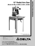
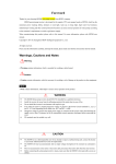
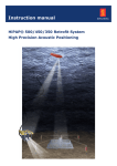
TOWERWORK
INSTALLATION PARTS
TE2T2S
Single cage
Double cage
Description with pictures
TE2T2S(Single-Left)
TE2T2S(Double)
TE2T2S(Single-Right)
INSTALLATION PARTS
TE2T2S--Single cage(left)
TOWERWORK
TE-L204-500
TE-L203-500
TE-L200-600
TE-L201-500
TE-L202-500
TE-L206-302
TE-L206-303
TE-L206-301
TE-L206-501
TE-L206-502
TE-L200-550
INSTALLATION PARTS
TE2T2S-- Single cage(Right)
TOWERWORK
TE-R206-302
TE-R204-500
TE-R206-303
TE-R206-301
TE-R200-550
TE-R206-501
TE-R206-502
TE-R203-500
TE-R201-500
TE-R202-500
TE-R200-600
TOWERWORK
INSTALLATION PARTS
TE2T2S-- Single cage(Left)
●Enclosure
TE-303-500
TE-306-002
TE-309-005
TE-306-001
TE-303-520
TE-309-001
TE-308-002
TE-308-001
TE-306-002
TE-308-005
TE-310-550
TE-303-500
TE-303-510
TE-309-004
TE-310-500
TE-306-002
TE-309-001
TE-306-001
TE-L301-100
TE-306-001
TE-305-500
TE-308-003
TE-300-500
In the foundation
TE-309-002
TE-306-002
TE-L311-500
TE-304-500
TE-L308-004
TE-306-001
TE-309-003
TE-307-500
TOWERWORK
INSTALLATION PARTS
TE2T2S-- Single cage(Right)
TE-303-500
●Enclosure
TE-306-001
TE-306-002
TE-309-001
TE-303-520
TE-309-005
TE-308-002
TE-308-001
TE-303-500
TE-308-005
TE-310-550
TE-306-002
TE-309-004
TE-306-001
TE-309-001
TE-306-002
TE-303-510
TE-310-500
TE-308-003
TE-300-500
In the foundation
TE-R301-100
TE-306-001
TE-306-001
TE-R308-004
TE-309-002
TE-305-500
TE-304-500
TE-R311-500
TE-306-002
TE-307-500
TE-309-003
TOWERWORK
INSTALLATION PARTS
TE2T2S-- Double cage
TE-306-002
TE-303-500
TE-309-006
TE-308-001
TE-303-520
TE-306-001
TE-308-003
TE-308-002
TE-R311-500
TE-309-006
TE-R308-004
TE-310-550
TE-306-001
TE-306-002
TE-303-500
TE-308-001
TE-303-510
TE-306-001
TE-309-006
TE-306-002
TE-308-003
TE-309-002
TE-309-006
TE-309-003
TE-310-500
TE-301-500
TE-L308-004
TE-300-500
In the foundation
TE-309-002
TE-306-002
TE-307-500
TE-L311-500
TE-304-500
TE-309-003
TE-306-001
TE-307-500
INSTALLATION PARTS
TE2T2S-- Single cage(Left)
TOWERWORK
TE-301-150
TE-301-140
TE-301-120
TE-301-130
TE-L301-100
TE-L301-500
INSTALLATION PARTS
TE2T2S--
Single cage(Right)
TOWERWORK
TE-301-150
TE-301-140
TE-301-120
TE-301-130
TE-R301-100
TE-R301-500
INSTALLATION PARTS
TE2T2S-- Double cage(Right)
TOWERWORK
TE-301-150
TE-301-150
TE-301-140
TE-301-140
TE-L301-100
TE-301-110
TE-301-120
TE-301-130
TE-301-130
TE-301-120
TE-301-500
TOWERWORK
INSTALLATION PARTS
TE2T2S-- Double cage(Right)
TE-303-520
TE-303-500
TE-L504-500
TE-502-520
TE-L504-500
TE-502-510
TE-L503-500
TE-R503-500
TE-502-510
TE-303-500
TE-L505-500
TE-R505-500
TE-502-520
TE-303-500
TE-303-500
TE-L209-500
TE2T2S--
Single cage(Left)
TE2T2S--
Single cage(Left)
TE-810-500
TE-207-510
TE-207-510
TE-207-510
TE-207-520
TE-207-520
992-080
992-080
TE2T2S--
Single cage(Left)
TE-800-550
TE-800-500
TE-800-560
TE-800-520
TE-800-540
TE-800-510
TE-800-530
TE2T2S--
Single cage(Left)
TE-208-506
TE-208-508
TE-208-510
TE-208-507
TE-208-505
TE-208-503
TE-208-502
TE-208-504
TE-208-501
TE-208-500
TOWERWORK
INSTRUCTION MANUAL
FOR TE2T2S
CONSTRUCTION HOIST
TOWERWORK,inc U.S.A. 7 OLD FIELD RD. 11733 NEW YORK
PHONE:+1 516 303 3004 FAX:+1 631 744 0414
Web:www.towerwork.net
TOWERWORK
INSTRUCTION MANUAL
FOR TE2T2S
CONSTRUCTION HOIST
TOWERWORK,inc U.S.A. 7 OLD FIELD RD. 11733 NEW YORK
PHONE:+1 516 303 3004 FAX:+1 631 744 0414
Web:www.towerwork.net
TOWERWORK
The manufacturer TOWERWORK guarantee machinery's conformity to the technial specification and instruction
written in this handbook at the issued date.
Duplication with any device, totally or partially,of this handbook is forbidden because it is exclusive property of
TOWERWORK.
Read carefully this handbook before start every job
Before start to operate you have to read this handbook.The guarantee of the product operation and the full
performance's correspondence of machine are depended from the application of all the instructions that are contained in
this handbook.
● HANDBOOK USAGE
This handbook provide rules and orientations which help you to use safety and correctly the Building Hoist and the
instruction to keep it efficent in its life.
Let the handbook easy to reach to allow all operators to read it periodically.
If the handbook will miss or become unreadable,please ask for a copy to the TOWERWORK.
Operators must be adequately trained and qualified to use the machine.
Make sure that the handbook is read and understood by the operators who have to use or maintain the machine,moreover the
handbook is specially made for building site's manager.
Handbook is a part of the plant.So that:
◆Keep it with care.
◆When sell the plant,the handbook must be delivered with it, to the new owner.
◆If the plant will be modified or upgraded,keep the handbook updated.
Precaution for preservation:
To keep the handbook in good condition ,holds it safe location near the machine.If it will wear or misss,do not hesitate to
ask for a copy at the manufacturer.To write notes,use the available blank pages,at the end of the handbook.
●
HOW TO READ THE HANDBOOK
TO IDENTIFY THE SAFETY MESSAGE,INPORTANT OPERATION AND RISKS,so the following tables are used to
catch the user attention,in order to ensure a correct and safe machine's use:
Danger
This picture is used where a residual risk with concrete possibility of permanent injury or death will remain.The
messages described safety cautions which have to be taken to avoid residual rosk.The fail of company with all is written
here can,also,damage the machine.
TOWERWORK,inc U.S.A. 7 OLD FIELD RD. 11733 NEW YORK
PHONE:+1 516 303 3004 FAX:+1 631 744 0414
Web:www.towerwork.net
TOWERWORK
Attention
This picture is used where a residual risk with concrete possibility of moderate injury will remain.This picture could be
used also where the only residual risk is to damage the machine.
●
HOW TO UPDATE THE HANDBOOK
If necessary to update the handbook please contact TOWERWORK.
TOWERWORK,inc U.S.A. 7 OLD FIELD RD. 11733 NEW YORK
PHONE:+1 516 303 3004 FAX:+1 631 744 0414
Web:www.towerwork.net
TOWERWORK
CONTENTS
Technial date
1.INTRODUTION • • • • • • • • • • • • • • • • • • • • • • • • • • • • • • • • • • • • • • • • • • • • • • • • • • • • • • • • • • • • • • • • • • • • • • • • • • • • • • •A-01
2.TECHNICAL DESCRIPTION • • • • • • • • • • • • • • • • • • • • • • • • • • • • • • • • • • • • • • • • • • • • • • • • • • • • • • • • • • • • • • • • • • • B-01
3.INSTALLATION FOUNDATION • • • • • • • • • • • • • • • • • • • • • • • • • • • • • • • • • • • • • • • • • • • • • • • • • • • • • • • • • • • • • • • • •C-01
Calculation of Static Load on the Foundation
Preparation of Foundation
Foundation Drawing
4.MAST AND TIE-IN • • • • • • • • • • • • • • • • • • • • • • • • • • • • • • • • • • • • • • • • • • • • • • • • • • • • • • • • • • • • • • • • • • • • • • • • • • • • D-01
Specifications and Selection of Mast section
The Distribution of Mast Tube Thickness
Installation of Tie-in and Cable Guide Frame(Cable trolly Device)
Reaction Force the Wall
5.OPERATING INSTRUCTION FOR HOIST • • • • • • • • • • • • • • • • • • • • • • • • • • • • • • • • • • • • • • • • • • • • • • • • • • • • • • • E-01
Safety Requirement
Operation
6.DROP TEST • • • • • • • • • • • • • • • • • • • • • • • • • • • • • • • • • • • • • • • • • • • • • • • • • • • • • • • • • • • • • • • • • • • • • • • • • • • • • • • • • F-01
Method of Drop Test
7.SAFETY DEVICE • • • • • • • • • • • • • • • • • • • • • • • • • • • • • • • • • • • • • • • • • • • • • • • • • • • • • • • • • • • • • • • • • • • • • • • • • • • • •G-01
Requirement for Using Safety Device
Restting the Safety Device
8.INSPECTION • • • • • • • • • • • • • • • • • • • • • • • • • • • • • • • • • • • • • • • • • • • • • • • • • • • • • • • • • • • • • • • • • • • • • • • • • • • • • • • • H-01
9.LUBRICATION • • • • • • • • • • • • • • • • • • • • • • • • • • • • • • • • • • • • • • • • • • • • • • • • • • • • • • • • • • • • • • • • • • • • • • • • • • • • • • • I-01
Oil for Reducing Device
Diagram
10.INSTALLATION • • • • • • • • • • • • • • • • • • • • • • • • • • • • • • • • • • • • • • • • • • • • • • • • • • • • • • • • • • • • • • • • • • • • • • • • • • • • • • • J-01
Preparation
Prepare Parts by User
Safety Requirement
Single Cage
Twin Cage
Lifting Device
Mast
Tie-in
Cable Trolly Device
Overload Device
Layer Calling Device
CAN200 Construction Hoist quick debug statement
11.DISMANTLE • • • • • • • • • • • • • • • • • • • • • • • • • • • • • • • • • • • • • • • • • • • • • • • • • • • • • • • • • • • • • • • • • • • • • • • • • • • • • • •K-01
Request of Safety
Cable Trolly Device
Mast and Tie-in
Drive Mechanism and Cage
Gound enclosure
12.ADJUST HOIST • • • • • • • • • • • • • • • • • • • • • • • • • • • • • • • • • • • • • • • • • • • • • • • • • • • • • • • • • • • • • • • • • • • • • • • • • • • •L-01
13.TRACING TROUBLE • • • • • • • • • • • • • • • • • • • • • • • • • • • • • • • • • • • • • • • • • • • • • • • • • • • • • • • • • • • • • • • • • • • • • • • M-01
14.CHANGE DAMAGED PARTS • • • • • • • • • • • • • • • • • • • • • • • • • • • • • • • • • • • • • • • • • • • • • • • • • • • • • • • • • • • • • • • •N-01
Pinions
Rack
Guide Roller
Roller
Safety Device
Brake Pads
Motor and Reducing Device
Brake Piece
15.ACCESSORY • • • • • • • • • • • • • • • • • • • • • • • • • • • • • • • • • • • • • • • • • • • • • • • • • • • • • • • • • • • • • • • • • • • • • • • • • • • • •O-01
Circuit
Damaged Spares
Check Cist
SC-1/A hoist overload protector
TOWERWORK,inc U.S.A. 7 OLD FIELD RD. 11733 NEW YORK
PHONE:+1 516 303 3004 FAX:+1 631 744 0414
Web:www.towerwork.net
TOWERWORK
Main Technical Data of TOWERWORK Brand of Construction Hosit
Remark:
1.The above technical data that we recommended specifications,but also cade dimension is according to requirement of customer.
2.The motor or reducer may choose German SEW products and reducer and choose turbo or rack,according to requirement of customer.
3.The data is for a reference only,the actual item is the standard.
TOWERWORK,inc U.S.A. 7 OLD FIELD RD. 11733 NEW YORK
PHONE:+1 516 303 3004 FAX:+1 631 744 0414
Web:www.towerwork.net
LIFTING DEVICE
MACHNIERY
CAGE
CABLE TROLLY
MAST
TIE-IN
GUARD RAIL
POWER CABINET
TOWERWORK
1
INTRODUCTION
1
SC construction hoist is driven by rack and pinion, and it is the vertical transportation equipment for lifting people and goods.It
mainlyused on the construction of high building. This construction hoist can install and dismantle very convenient, and it can grow
as high as the building growing in height. SC hoist has the following features:
The safety protecting devices are complete and reliable. It has the anti-dropping safety device with national proprietary
technology, make the working reliability of this machine rank first among similar products. Combined type design, two suspension
cages can take apart and install separately. Through different combinations, it can combine many specifications of the
construction hoist with different speeds、different lifting weights. It can improve the standard、practicability and unification of the
products greatly.
Running smoothly、riding comfortable. Because this machine is put the driving unit on the top of the suspension cage, make
the space of the suspension cage inside big; at the same time also make the driving more smoothly、less mechanical shaking,
and give the construction workers a comfortable、commodious environment.
It adopts normal control and frequency control for the electric control part, each type has its advantages and can meet the
requirements of different customers.
TOWERWORK,inc U.S.A. 7 OLD FIELD RD. 11733 NEW YORK
PHONE:+1 516 303 3004 FAX:+1 631 744 0414
Web:www.towerwork.net
A-01
TOWERWORK
2
TECHNICAL DESCRIPTION
2
1.Guide frame: guide frame is connected with the mast by the strength bolt M24×230,
and fix with the building by attachment frame as the operation rail of the hoist. The
length of each mast is 1508mm, the section width between centers is 650x650mm, the
modulus of the rack is 8mm.
The mast of the single cage construction hoist has one rack, it can be changed into
the mast of the double cage construction hoist by adding one more rack.
The mast can do hot-dip galvanizing handling according to the requirements of the
customers, so that it can improve the strength and antiseptic property of the mast.
2.riving body:The driving body is the components which connected the drive units and between the drive units and the
monolithic construction. It transmits the driving force produced by the drive unit to the suspension cage and makes the cage run
up and down.
3.Drive unit:The drive unit is the dynamic part of the hoist, the hoist operates when two
groups、three groups of drive units which are working and operate interacting at the same
time, driving the deadweight part of the hoist and loaded suspension cage load (or the staff)
operated up and down. The unit is made of with driving gear、reducer、coupler、plumshaped elastic coupler、brake motor etc. The reducer is planer enveloping worm reducer,
its characteristics are compact conformation、 high bearing capacity、 high mechanical
efficiency、 have long performance life、smooth work etc. The normal control system
adopts the reducer speed ratio 16、18, the frequency control adopts the reducer speed
ratio 8.2、10、12. The coupler is reeling pawl type, between two couplers, there has rubber
buffer used to lighten the impaction and vibration when it is driving. The motor type is
YZEJ132M-4 disc brake three-phase asynchronous motor, its brake electromagnet can
track automatically with the abrasion of the brake disc, and can adjust the brake moment.
4.lectrical system: Electrical system is the directive mechanism part of the hoist, all actions of the hoist are directed by the
electric system. The electrical control system has two types: normal electrical control and frequency electrical control. The normal
electrical control has the features such as simple structures, convenient、easy operation and maintenance, low cost etc. But the
frequency electrical control is with wide speed governing range, can be started and stopped smoothly without attack and with wide
speed range, speed balanced and smoothly. Electrical system includes upper electrical box, lower electrical box, cabin control
board and main control cable etc. To adopt which type of control system is according to customers' requirements.
5.afety base plate: Safety base plate is the connected component between tripper and other structures, on which is the antidropping tripper received the national patent. If the suspension cage falls down with high speed accidentally, the safety base plate
can afford the wallop of stopping the suspension cage.
TOWERWORK,inc U.S.A. 7 OLD FIELD RD. 11733 NEW YORK
PHONE:+1 516 303 3004 FAX:+1 631 744 0414
Web:www.towerwork.net
B-1
TOWERWORK
6.nti-dropping tripper: SAJ type anti-dropping
tripper
is
the
technique product with national patent, which is produced under
advanced technology that of engaging-in flinging block without
impaction、no need to dismantle and it can check the wearing capacity
of the frictional damping band. When the suspension cage falls down
with excessive speed, it can stop the suspension cage smoothly on the
guide frame, and cut off the power, make sure the safety of the staffs
and equipment. The excitation speed of the tripper has adjusted and
stamped the lead seal when it leaves the factory, the users can't open
the tripper unauthorized, or the consequence is proud. On the tripper
plate marked lifetime, after it reaches its lifetime, it should send to the
manufacturer to re-align.
7.imit device: Limit device includes upper、lower travel spacing block and the upper、lower travel limit block so that when the
suspension cage drives to the upper、lower assigned location, it can cut off the power immediately and stop the hoist. Limit blocks
ensure that after suspension cage drives to the upper、lower spacing, cut off the power immediately when continuing driving
accidentally because of the fault of the spacing switch, make the suspension cage stop and make sure that the suspension cage
drives up without puking, drives down without hitting the bottom. The limit switch doesn't have self resetting type, it only reset by
manually operation. Should often check whether the position between these blocks and relative switches is right to make sure the
actions of each switch is ok.
8.ain control box: Main control box is the heart of the hoist electric system. The main control box of the normal control system is
installed inside the suspension cage, there have upper、lower driving contactor、control transformer、overheat protector and
fault-phase and phase-sequence protection relay and etc inside the main control box. The main control box of the frequency
control system is installed on the top of the suspension cage, there have electric elements such as transducer、resistance box
and etc inside the main control box.
9.age: Cage is a steel structure, and it has in-out sliding door.
10.ectric power box: The electric power box is the power supply of the construction hoist control part, it is installed on the
ground guardrail of the cont
11.derframe guardrail: Mainly includes two parts of underframe and protective enclosures.
11.1 The underframe is welded by the profiled bar (channel steel) and armor plate, the around of it connect with the ground
protective enclosures, the guide frame base is in the centre. It can support all vertical load transmitted by the hoist. When
installing, underframe fixes with the concrete base of the hoist through the anchor bolts.
11.2 Protective enclosures are welded by the angle iron、 armor plate and steel mesh grid, it surrounds the hoist core parts to a
closed region, so the workers can't enter the region when the hoist works. The guardrail door is located at the entrance of the
protective enclosures, on the door has electromechanical interlocking device.
12.ble drum: Cable drum is used to receive and release the parts of main cable. When the hoist drives up, the suspension
cage will drive up with the main cable in the cable drum, when the suspension cage drives down, main cable moves into the cable
drum slowly to prevent danger if the main cable drops on the ground to be destroyed.
TOWERWORK,inc U.S.A. 7 OLD FIELD RD. 11733 NEW YORK
PHONE:+1 516 303 3004 FAX:+1 631 744 0414
Web:www.towerwork.net
B-2
TOWERWORK
13.ble guide frame: Cable guide frame is located for protecting the cable, when the hoist works, it ensures the cable in the
guard ring of the cable guide frame, cable guide frame can prevent cable enwinding other equipments to be danger when the cage
drives. When installing cable guide frame, it should ensure the cable jib and main cable can pass through the guard ring on the
cable guide frame favorably.
14.e-in: Tie-in is the connection component between
guide frame and building, it used for keeping the
stability of the guide frame and the whole structure of
the hoist. In addition,tie-in also supplies the installing
position for the cable guide frame.
15.ble jib: Cable jib is the device to drag the main cable for driving up and down,
the main cable dragged by the cable jib, it can be safely through the cable guard ring
and prevent the accident because of the scuffing cable. In addition, the cable jib can
pick the main cable out of the guardrail and receive the main cable into the cable
drum safely.
16.fting device: Lifting device is the indispensable part to achieve self raise and self
dismantlement, after installing the foundation part of the hoist, we can use the lifting device to hang
the mast on the top and inside cage to the top of the installed guide frame for raising, conversely,
when dismantling, lifting devicecan dismantle the guide frame mast from up to down.
17.ble trolly: When the hoist is higher (more than 150m generally), it is limited by the supply
power and cable mechanical intensity, so we should adopt the middle supplying power method,
exploiting the trolly system to storage moving cables.
18.erload device:Select overload alarm equipment in cage,the
alarm rings and cage can't start while overload.
19.yer-calling system:Select layer-calling system according to
need,when calls at layer,the receiver receive the information,picture
and sound happen on main unit in cage.
TOWERWORK,inc U.S.A. 7 OLD FIELD RD. 11733 NEW YORK
PHONE:+1 516 303 3004 FAX:+1 631 744 0414
Web:www.towerwork.net
B-3
TOWERWORK
3
3
INSTALLATION FOUNDATION
The foundation of the hoist should meet the requirement of the installation and the local safety regulation。
The load on the foundation can not be less than P.
Careful draining is required around foundation.
● Caculation of static load on the foundation
1.Calculation of total weight
BASE
CAGE
G =
+
(kg)
FRAME
LANDING
GUARD RAIL
+
+
FRONT
(kg)
POWER CABINET
+
+
STRUCTURE(kg)
(kg)
MAST
(kg)
LOAD
+
(kg)
DOOR(kg)
2.Calculation of static load on the foundation(the factor is 2)
P= G x 2(kg)
∵1kg= 9.8 N
= 0.0098 kN
∴P= G x 2 x 0.0098 kN
= G x 2 x 0.0196 kN
P= G x 0.02(kN)
EX. SC200/200,erection height is 100 m.
Weight of the Cage(double cage):2 x 2000 kg
Weight of the base frame:450 kg
Weight of the guard rail:400 kg
Weight of the landing front door:2 x 170 kg
Weight of the power cabinet structure:100 kg
Weight of the mast:9570 kg
Load capacity of the cage(double cage):2 x 2000 kg
Total weight
G=2x2000+450+400+2x170+100+9570+2x2000=18860
The load of foundation is equal to:
P= G x 0.02(kN)=18860x0.02=377 kN
Pmax for the concrete slab is 377 kN,which means that the foundation strangth is more than adequate in the above instance.
TOWERWORK,inc U.S.A. 7 OLD FIELD RD. 11733 NEW YORK
PHONE:+1 516 303 3004 FAX:+1 631 744 0414
Web:www.towerwork.net
C-1
TOWERWORK
●Preparation of foundation
●Proposal 1
Concrete slab on the ground
Advantage: No draining required
Disadvantage: high still
●Proposal 2
Concrete slab level with the ground
Advantage: simple draining
Disadvantage: sill, used in combination with a simple wooden
●Proposal 3
Concrete slab below the ground level
Advantage: No sill between ground and suspension cage
Disadvantage: high corrosion id water remains on the
foundation. Requires careful draining.
Important: Please note that there is risk of frost, the ground should always be
insulated, freeze the surrounding soil should always be avoided.
TOWERWORK,inc U.S.A. 7 OLD FIELD RD. 11733 NEW YORK
PHONE:+1 516 303 3004 FAX:+1 631 744 0414
Web:www.towerwork.net
C-2
TOWERWORK
● Foundation drawing
A concrete slab is to be made according to the following instructions, and
according to the actual model of hoist.
It is important that the mounting holes of the foundation frame are brought in
level with the completed concrete surface ,and that the concrete is vabrated
thoroughly - especially around the foundation frame.
It is also important that the finished surface is plane and horizontal.
foundation frame
Technical requirements:
1.The load on the foundation should be more than P;
2.The ground pressure under the foundation should be more than 0.15Mpa;
3.Double mesh reinforcement:Rods 12 mm,distance 200 mm;
4.equired draining way.
TOWERWORK,inc U.S.A. 7 OLD FIELD RD. 11733 NEW YORK
PHONE:+1 516 303 3004 FAX:+1 631 744 0414
Web:www.towerwork.net
C-3
TOWERWORK
4
MAST AND TIE-IN
● Specifications and Selection of Mast section
Installation height of the hoist is different, the type of the mast section tube is not the same, their choice is as follows:
Φ76x4.5
Φ76x6.3
Φ76x8.0
EX:installation height is 280 m from the picture 3:
Φ76x4.5
installation 140 m
93 sections
Φ76x6.3
installation 120 m
80 sections
Φ76x8.0
installation 280-140-120=20 m
13 sections
TOWERWORK,inc U.S.A. 7 OLD FIELD RD. 11733 NEW YORK
PHONE:+1 516 303 3004 FAX:+1 631 744 0414
Web:www.towerwork.net
D-1
4
TOWERWORK
● The Distribution of Mast Tube Thickness
TOWERWORK,inc U.S.A. 7 OLD FIELD RD. 11733 NEW YORK
PHONE:+1 516 303 3004 FAX:+1 631 744 0414
Web:www.towerwork.net
D-2
TOWERWORK
● Attachment of Tie-in
EX 1 :The tie-in are attached to
EX 2 :Fixed by bolts
embeded brackets of building
EX 3 : Embeded bolts
EX 4 : Welded into steel structure
According to need, please select the method for tie-in attached to the building and prepare the bolts and
parts , the strength of which can support the force F as the formula above (you can select bolt of M24 ,
the strenght is 8.8).
● Dimensions of Tie-in
TOWERWORK,inc U.S.A. 7 OLD FIELD RD. 11733 NEW YORK
PHONE:+1 516 303 3004 FAX:+1 631 744 0414
Web:www.towerwork.net
D-3
TOWERWORK
● Instalation of cable guide frame(cable trolly device)
The spacing of tie-in shall not exceed 10.5m!
TOWERWORK,inc U.S.A. 7 OLD FIELD RD. 11733 NEW YORK
PHONE:+1 516 303 3004 FAX:+1 631 744 0414
Web:www.towerwork.net
D-4
TOWERWORK
● Reaction force P on the wall
The force on the wall can be obtain from the following formula:
L x 60
P=
2.05
Bx
kN
EX:B=1530 mm, L=3500 mm
P=
L x 60
B x 2.05
kN =
3500 x 60
1530 x 2.05
TOWERWORK,inc U.S.A. 7 OLD FIELD RD. 11733 NEW YORK
PHONE:+1 516 303 3004 FAX:+1 631 744 0414
Web:www.towerwork.net
D-5
= 66.95 kN
TOWERWORK
5
OPERATING INSTRUCTION FOR HOIST
5
Safety requirement
1.The operator must be trained so that he is familiar with the operation of the hoist and the function of all parts. 2.Never operate
the hoist when wind speeds at the top of the hoist exceeding 20m/s and foul weather condition. 3.No obstacles in the hoist
way.
4.No accumulated water in the foundation.
5.Keep the cage clean.
6.The stuffs must be placed steadily in the cage for the sake of guarantee all the things not incline and overturn. 7.Make sure that
the load is less than payload.
8.Not open door and let hand or aomething out of cage while running. 9.Be away
to everyone while start.
10.Must check the cable whether be dlivorced from cable guide in every working day. 11.The
passsenger and stuffs can not lean close to the any doors.
12.Stop the cage at the ground landing,lock the 3-phase switch and cut off the power when work is finished for the day. 13.Only fixed
person can inspect.
14.Not operate after drinking.
15.Operate at cage roof while installation.
16.Make sure that the inspection ,maintance and drop test must be done periodically.
17.The frequency conversion before start the fan and varsity must be good to alternating hoist.
If main power is off , wait 3 second to start hoist after switch on to alternating hoist. Ten
minutes after main power is off,you can in spect to alternating hoist.
Power box
●Operation
1.
Turn the switch to "NO" and lock it.No one can cut off easily when it
Lock
turn on.
You can turn the switch to "OFF" exertly in the urgency,but you must
replace the switch after it.
When you turn the switch to "OFF" and lock it, no one can turn on
easily.
2.Close the door.(incl. the cage gates,the enclosure gate,the trap
door).Make sure the door can lock reliably.
Door lock
Manul ramp door
TOWERWORK,inc U.S.A. 7 OLD FIELD RD. 11733 NEW YORK
PHONE:+1 516 303 3004 FAX:+1 631 744 0414
Web:www.towerwork.net
E-01
TOWERWORK
Attention shouold be called,before the hoist is started.
3.Turn on the 3-phase switch.Make sure that no fuses are blown and
emergency stop button and EL. Lock are turn on.
4.Make sure the top,bottom and delay limit switches are reliable.
5.Press the bell first then put the lever in position with symbol for desired direction and keep it there where up on the hoist
starts,release the lever to its neutral position to stop the hoist .At the grouond landing and top landing ,the hoist can stop
automatically.
6.The frequency conversion should push start button 2 second.After
3 second,put the lever at low speed position. After 3 second ,put the
lever at high position.
Before stop cage normally,turn the level to low speed
position, after 3 second, you can stop.
Do not start the cage if the cage does not stop steadily.
If the electricity is cut off,you can start the cage only after 2 minutes.
7.If abnormal phenomena take place,press the emergency stop button and depress it untill the troubles are solved. 8.Pull
the control box through the trap door when working at the roof of the cage.
9.If the hoist stop abnormally,drive it down to the ground landing by hand.Lift the brake lifter on the motor to allow the cage to
slide down slowly.
10.The hoist can be assembled with automatically device according to need.There is no need to specially arrange any
operator,passengers can press or stop at whatever layer they want through press layer choice button. Besides, people who
in building can also make the hoist deliver the cargos to the desired landings by itself through a bottom operation that sends
the signal to the cage.Be note:should more care for the hoist maintenance and repairing if the hosit working under the latter
method.
The sliding speed should be less than the specified speed,otherwise the safety device will trip.Rest for one
minuts after each 20m down in order to cool the brake.Sliding down by hand must bedone by the service
person.
IF the hoist does not start --check that:
1.The main switch of power box is turned on and that there is electrc power to the hoist. 2.The
emergency stop button is not pushed in.
3.The 3-phase switch is turned on. 4.The
trap and cage doors are closed. 5.The
enclosure doors are closed.
TOWERWORK,inc U.S.A. 7 OLD FIELD RD. 11733 NEW YORK
PHONE:+1 516 303 3004 FAX:+1 631 744 0414
Web:www.towerwork.net
E-2
TOWERWORK
9.If no output,please call for help.
10.Up the bottom limit phase,limite phase for accelerate in function or not.
11.Whether the switch of safety device in function or not.
6.The slack rope switch on the cage has not been tripped.
7.Circuit breaker does not trip.
8.If the frequency converter has output.
Manually release the motor brake
Lift the brake lifter on the motor to allow the cage to slide down slowly.
TOWERWORK,inc U.S.A. 7 OLD FIELD RD. 11733 NEW YORK
PHONE:+1 516 303 3004 FAX:+1 631 744 0414
Web:www.towerwork.net
E-3
TOWERWORK
6
6
DROP TEST
A drop test must be carried out at every new installation and reinstalliton after the hoist is repaired.At least every six month or
in accordance with local safety regulations during operation.
Safety device should be delivered to the factory and inspected after two years.If it si up to standard,it can be used
continuously.The life of safety device is 5 years.
DANGER!
Brake malfunction hazard!
No one is allowed in the hoist during a drop test.
Will cause severe bodily injury or death.
If the safety device begins to trip, or if noise occurs in the safety device during operation, the
hoist must be taken out of service immediately and the local TOWERWORK representative be
notified for action.
"UP" button
"DROP" button
Method of Drop Test
1.The hoist must be full of load when dropping test.
2.Cut off the main power supply. Connect the cable of the
drop test button box into the EL.control box(see figure).
3.Pull the push button box and the cable out though the gate and
put the botton box on the ground.Make sure that the cable can'tget
jammed or stuck. Crose all gates.
4.Turn on the main power awitch.
5.Drive the cage about 10 meters up by pressing the “UP”button.
6.Press the “Drop”-button and keep it depressed. The cage will
fall till it reaches tripping speed and the safety device is
actuated and the main power is cut off.The braking distance fit to
the sheet.Count the braking distance as soon as hearing”bong”.
7.Drive the cage about 0.2m up by pressing the “UP”-button.
8.Drive the cage down slowly by inching operation.
TOWERWORK,inc U.S.A. 7 OLD FIELD RD. 11733 NEW YORK
PHONE:+1 516 303 3004 FAX:+1 631 744 0414
Web:www.towerwork.net
F-1
TOWERWORK
The distance of safety device stopping
Note:Release the button at once,if the cage does not stop at least 3m
above ground landing.Then drive the cage down to ground by inching
operation.Investigate the cause.
Note:The fall distance by each inching operation should be less than
0.2m,otherwise the safety device will be trip again.
TOWERWORK,inc U.S.A. 7 OLD FIELD RD. 11733 NEW YORK
PHONE:+1 516 303 3004 FAX:+1 631 744 0414
Web:www.towerwork.net
F-2
TOWERWORK
7
SAFETY DEVICE
7
Requirement Using Safety Device:
1. The safety device are adjusted and sealed. Do not disassemble it.
2. If the safety device trip abnormally when drop rest investigate the cause and reset
the safety device.
3. Stop using it at once and change a new one for it when abnormal
phenomena take place.
4. The hoist can not start unless the safety device is reset after it tripped.
Resetting the safety device:
If the safety device trips during normal operation, a careful check must be made of the motor brake(s), transmissions, pinion,
rack and all guide and counter rollers by trained authorized service personnel, before the safety device can be reset. The cause
of the tripping must be determined and rectified.
The safety device may be reset after a drop test, without having to carry out the checks listed above.
WARNING!
Falling hazard!
Never reset the safety device above ground landing. Can
cause severe injury or death.
A socket intended for a 19.05mm drive ratchet comes with the hoist delivery to simplefy the safety device’s resetting
procedure.An drive extension tube further simplify the procedure.
(The 19.05mm drive ratchet is NOT a part of the hoist delivery).
TOWERWORK,inc U.S.A. 7 OLD FIELD RD. 11733 NEW YORK
PHONE:+1 516 303 3004 FAX:+1 631 744 0414
Web:www.towerwork.net
G-1
TOWERWORK
Disconnect the button box with plug after drop test.
Before the safety device is released the cause of the tripping should be investigated. Beside the drop test, check that: 1.The
brake is in order.
2.The reducing device and coupling are in order.
3. The guide rollers and counterweight rollers are in order.
4. Pinions and rack are in order.
5.The micro switch of the safety device is in order.
Cut off the main power and reset the safety device as follows:
SAJ40-1.6
SAJ40-2.0
SAJ50-1.0
SAJ50-1.2
① Remove the screw 1 and lift the cover 2.
② Remove the screw 3.
③ Use the special tool 5 and cranding lever 4 to unscrew the nut 7 until the end
of the pin 6 is level with the end of the safety device.
SAJ30-1.2
SAJ30-1.6
SAJ40-1.2
④ Install the screw 3 and the cover 2.
⑤ Remove the cover 9.
⑥ Tighten screw 8 by hand as much as possible then use the tool tighten the screw
8 to another 300. After hearing “ping”, release the screw 8.
⑦ Fit the cover 9.
⑧ Turn on the main switch and drive the hoist about 20cm upward to reset the
centrifugal weight of the safety device.
If “L” is more than 8mm after
drop test, check the safety
device, it must be exchanges
if necessary.
TOWERWORK,inc U.S.A. 7 OLD FIELD RD. 11733 NEW YORK
PHONE:+1 516 303 3004 FAX:+1 631 744 0414
Web:www.towerwork.net
G-2
TOWERWORK
8
8
INSPECTION
Cut off main power 10 minutes before checking.
Daily:
1.Check the outer power switch、the total switch on enclosure gate: the hoist can not start when the gate is opened.
2. Check and make sure that the 3-phase switch、limit switches and delay switch cams are in order.
3. Check the safety switches as follows. The hoist can not start every time.
a. Open the Ent. Door of the cage.
b. Open the Ext. Door of the cage.
c. Open the trap door.
d. Press the slack rope switch
e. Press the emergency stop button.
4. No obstacle in the counterweight and cage way.
5. Check counter roller whether be divorce from counterweight rail.
6. Check cable whether be divorce from cable Guide.
7. Check the interval of engagement between pinion and rack. Make sure that the interval is 0.2mm-0.5mm.
8. The frequency conversion should check fan and resistance.
● Check the frequency's temperature.
● Check the output current of frequency converter.
Weekly:
1. Ensure that all screw joints of the machinery plate are tightened.
2. Make sure that all lubricating parts are lubricated.
3. Make sure that all screw joints in racks、guide rollers and roller assemblies、 mast tie-in and mast sections are
tightened.
4. Make sure that all screw joints in cable support and cable guiding sections are tightened.
5. Make sure that all screw joints on the top wheel are tightened. The top wheel rotate easily and has no abnormal noise.
6. Make sure that the guide rollers of counterweight rotate easily. Inspect the steel rope.
7. Make sure that the electric motor have no noise and it does not generate heat.
TOWERWORK,inc U.S.A. 7 OLD FIELD RD. 11733 NEW YORK
PHONE:+1 516 303 3004 FAX:+1 631 744 0414
Web:www.towerwork.net
H-1
TOWERWORK
Quarterly:
1.Check the rollers, all pulleys and the bearing of guide rollers. Adjust or change them if necessary.
2.Check the wear of rollers. Adjust the interval between roller and vertical pipe. Then interval is 0.5mm. Loosen the nut,
rotate the shaft for calibrating and then tighten it.
3.Check the isolation resistance of motor and electric circuit, and the earth resistance of crust.
4.Make a drop test to check the safety device.
5.Check brake pads with a feeler gauge.
6.The frequency conversion should check the connection.
Check the varistor.
Check the basal plate.
Check the fan.
Check the power unit.
Annually:
1.Check the damage of the cable. Repair or change it if necessary.
2.Check the wear of the rubber in coupler.
3.Ensure that the steel rope of counterweight is not deformed and its end is attached tightly.
4.Inspect and maintain all parts or change then if necessary.
5.The frequency conversion should check the electricity capacity.
Check the worm cog:
Dismantle the inspection plug on the gear housing and check the wearing of the worm wheel.
Place the gauge with the end marked 100% perpendicular and in the center of one of the cogs.
If the groove enters the cog, the worm wheel is worn out. If not, turn the gauge and check if it is more less than 50%.
Inspecrion plug
TOWERWORK,inc U.S.A. 7 OLD FIELD RD. 11733 NEW YORK
PHONE:+1 516 303 3004 FAX:+1 631 744 0414
Web:www.towerwork.net
H-2
TOWERWORK
Check the pinion:
Check the wear of the pinion. New pinion: 37.1mm. Max. worn pinion 35.1mm.
Calliper(order)
Check the wear of the pinion:B-2≤3mm.
Check the rack:
Check the wear of the rack. The thickness of a new rack tooth is 12.56mm. Max. worn rack tooth 10.6mm. Measure the
wear with the rack gauge. If the gauge reached the bottom, the rack must be replaced.
New rack
Max. worn rack
Rack gunge(order)
Check the brake torque:
Check the brake torque by lever and spring balance. The torque of Zhang Jiang 15Kw motor is 170N.m±25%.
TOWERWORK,inc U.S.A. 7 OLD FIELD RD. 11733 NEW YORK
PHONE:+1 516 303 3004 FAX:+1 631 744 0414
Web:www.towerwork.net
H-3
TOWERWORK
Maintain the frequecy parts:
TOWERWORK,inc U.S.A. 7 OLD FIELD RD. 11733 NEW YORK
PHONE:+1 516 303 3004 FAX:+1 631 744 0414
Web:www.towerwork.net
H-4
TOWERWORK
9
9
LUBRICATION
Lubricate all following lubricate spots before the installed hoist is operated, lubrication interval is as following diagram or once
week when hoist is operated normally.
Clean the parts and then oil them.
Oil for reducing device:
To ensure the reducing device is in order, please refer to the instruction. In addition, the following oil brands , can be used.
TOWERWORK,inc U.S.A. 7 OLD FIELD RD. 11733 NEW YORK
PHONE:+1 516 303 3004 FAX:+1 631 744 0414
Web:www.towerwork.net
I-1
TOWERWORK
Diagram:
After running 40 hours for the first time, the reducer should change the lubricating oil, after that do as following list:
Change oil after the
device used a week.
new reducing
TOWERWORK,inc U.S.A. 7 OLD FIELD RD. 11733 NEW YORK
PHONE:+1 516 303 3004 FAX:+1 631 744 0414
Web:www.towerwork.net
I-2
TOWERWORK
TOWERWORK,inc U.S.A. 7 OLD FIELD RD. 11733 NEW YORK
PHONE:+1 516 303 3004 FAX:+1 631 744 0414
Web:www.towerwork.net
I-3
TOWERWORK
10 INSTALLATION
10
The installation should meet the requirement of installation and the local safety regulation.
Preparation before Installation:
1.
Make sure that there is power supply in the erection place. Provide a power box specialized for the hoist and a switch for
each cage. Fuse current see technical data.
2.
The distance between transformer substation and the main power of site should be no more than 20m.The Section of
copper cable should be more than 25mm2 and be increased.
3.Make sure that three is the lifting equipment and tools at the erection place.
4.
Make sure that the road and yard are prepared to receive and transport the hoist and its parts.
5.Cast a foundation in accordance with instructions.
6.
Select the method for installation of tie-ins. Prepare the casting fame and fixing parts if necessary.
7.
Prepare the landing accessories such as bridges and railings according to the requirement of user. Landing door could be
ordered from this factory.
8.According to equivalent ordinance and requirement to set up device of ground connectionR≤4Ω.
9.
Stipulate and require that when the Maximum warp of power supply voltage is ±5%, electric power of power supply can not
less than motor general power.
10.If used generator for power supply at the working site, must outfit no power compensated equipment and steady
pressure equipment, for the sake of guarantee the quality of power supply.
11.Worksite should be equipped with suitable creapage protection switch.
Excepting the following parts which is supplied by user, all parts for the hoist must be
supplied by this factory. Do not use the parts which are not permitted by this factory.
Prepare parts by User:
1.
Cast the foundation according to requirement. Prepare some 2-
12mm thick washers to put under the base for adjusting the straightness
of mast.
2.
Prepare the specified power box and connecting cable according to
requirement.
3.
Prepare the same cable for connection specified box and hoist power
box. The length is as short as possible. The longest cable is not more than
20 meters.
4.Prepare the bolts and embedded parts.
5.
Prepare a set of tools used for erection besides the specified tools
Note:There tools were prepared
by user.
provide with the hoist.
TOWERWORK,inc U.S.A. 7 OLD FIELD RD. 11733 NEW YORK
PHONE:+1 516 303 3004 FAX:+1 631 744 0414
Web:www.towerwork.net
J-1
TOWERWORK
Safety requirement for installation
1.Clean the erection place and fence it with railings. No admittance except on business.
2.Provide a safety net to prevent anything fall down to the erection place.
3.There must be the person who has specific duty for installation.
4.All parts on the cage must be put steadily and kept within the safety railing.
5.The lifting device only use for installing and dismounting parts and can not be permitted overload. 6.Do
not start the cage when the lifting device is being used.
7.The installing persons must put on the safety cap, safety belt, no slide shoes and so on .
8.Before operation ,at first connect protection device of ground connection to metal structure of the hoist R≤4Ω. 9.The
number of dynamic system must be in line with cage number.
10.All the parts must be adopted our company's Original copies, or else ,there would be the safety hidden trouble.
11.Without our permission , users can not change the hoist circuitry optionally.
Safty lock
Grounding device connection diagram
12.No install at night or after drink.
13.Persons' head and hand can not be out of the safety railing when the hoist is operating.
TOWERWORK,inc U.S.A. 7 OLD FIELD RD. 11733 NEW YORK
PHONE:+1 516 303 3004 FAX:+1 631 744 0414
Web:www.towerwork.net
J-2
TOWERWORK
14.Do not start the hoist when someone is working at the mast and tie-in. None allows to go into the enclosure when the cage
goes up.
15.The control box must be taken to the roof of the cage when installing the hoist. Nobody allows operating the hoist in the
cage.
16.Inspection every parts before the hoist is started.
17.During operation, the load must be less than payload.
18.The installation can not be done when snow, storm and the wind speed exceeding 13m/s. 19.Do
not forget tighten joint bolts of mast sections and tie-in.
20.Inspect and adjust vertical of mast when installed tie-in.
21.After installed, lubricate according to Manual.
Installation of hosit
The twin o single cage hoist with the enclosure are combined and adjusted by
experts for convenient installation.
If the hoist has been used before, it should be inspected in accordance with
“Inspection ” first. Should any parts such as safety device, pinion, and rack has been
damaged or worn to the allowable maximum amount it must be replace.
Installation of single hosit
1.Sweep the surface of the foundation.
2.Installed foundation Metal, fixed the screw.
3.Installed foundation mast, fixed the screw.
4.Installed spring under the cage.
5.
Lift the cage and put it in position.
6.
Loose the electric motor brake. Dismounting method: make note then dismount the two pins. Loose the two nuts
parallely until the brake loose and the brake disc can be rotated.
7.Lift the driving-vehicle with the lifting equipment.
8.Locate the driving-vehicle precisely from top of the mast section.
Base frame
TOWERWORK,inc U.S.A. 7 OLD FIELD RD. 11733 NEW YORK
PHONE:+1 516 303 3004 FAX:+1 631 744 0414
Web:www.towerwork.net
J-3
TOWERWORK
9.Adjust driving-vehicle and the cage with the ear board in same line, then insert a transmission pin, then fix it with split pin.(If it
is a lift installed with overload device insert a sensor pin, then let the limit slot on the top side, firm it with board ). 10.Replace the
brake.
11.Measure the uprightness of the mast with a water lever or plumb line. Ensure the straightness of each vertical pipe of mast is
less than 1/1500 in two directions.
12.Adjust the hoist mast by putting solid steel washers between the frame and the foundation. 13.When
the mast is absolutely straight, tighten the screws with a tightening moment of 350N.m.
14.Adjust the straightness of the enclosure front gable with a water level or plumb line. Ensure the strightness of the
enclosure front gable is less than 1/1000 in two direction.
15.Install the safety railing on the cage roof.
16.Adjust the lock of door (see figure).
Cage door lock
Enclosure door lock
Overload device
TOWERWORK,inc U.S.A. 7 OLD FIELD RD. 11733 NEW YORK
PHONE:+1 516 303 3004 FAX:+1 631 744 0414
Web:www.towerwork.net
J-4
TOWERWORK
Installation of double hosit
1.Install the left part of the hoist according to the above instructions.
2.Connect the right part of enclosure by bolts.
3.
Adjust the straightness of the enclosure front gable. Fasten the screws to the.
4.
Loose the electric motor brake. Dismounting method : make note then dismount the two pins. Loose the two nuts
parallely until the brake loose and the bake disc can be rotated.
5.Lift the cage with lifting device.
6.
Put down the cage to the exact position.
7.Replace the brake.
The nuts of brake must be screwed up to the marked position then fit the pins.
Installation
of
sperated
hoist
When a hoist is separated due to transportation, assemble the enclosure and adjust the straightness of mast and
enclosure front gable, then install the cage according to the instruction above.
Adjustment After the Installation
1.
Remove the wooden beams or bots used during transportation.
2.Make sure that the play for pinion in engagement with rack is 0.2mm-0.5mm.
3.
Make sure that the interval between the back of the rack and the guide rollers is 0.5mm.
4.Make sure that the interval between each roller and the mast pipe is 0.5mm.
5.All doors should be opened and closed easily.
6.Install the buffer spring.
Installation of Lifting Device
Put the lifting device into the position on the cage roof(You should connect power for electric lifting device).
Securely connected
with the M12X45 the
bolt
TOWERWORK,inc U.S.A. 7 OLD FIELD RD. 11733 NEW YORK
PHONE:+1 516 303 3004 FAX:+1 631 744 0414
Web:www.towerwork.net
J-5
Securely connected with
the M12X45 the bolt
TOWERWORK
Erection of the mast
1.
Clean the two ends of mast vertical pipe and rack pins. Lubricate them.
2.
Open a section of the safety railing. Wind down the hook to attach the mast's hanger.
3.Attach a mast section with mast's hanger.
4.
Lift the mast section up to the cage roof by winch.
5.
Close the safety railing. Drive the cage up as close to the mast top as possible. The distance to the top of the mast is about
300mm.
6.
Lift up a mast section with the lifting device. Put it down into the vertical pipe and the pin holes of the rack. Tighten the
bolts.
7.Release the hook and turn round the lifting device to tighten all bolts. Tighten moment 300N.m
8.
Continue as above until the final mast height has been reached. Do not forget the tie-in. Measure the straightness of the
erected mast sections.
Allowable Deviation Of Straightness
● Measuring straightness by theodolite or other instrument.
9.
If a suitable lifting device such as tower crane is available on the site,4-6 sections can be assembled on the ground and lifted
up to the mast top.
Installation of tie-in
1.stall two brackets on the mast. Tighten them with screws.
2.tach the two pipes on wall bracket.
3.in the other parts by screws and pins. Adjust the distance at every direction. Calibrate the straightness of the mast. 4.ghten
all screws. Start the hoist slowly, and make sure that the cage and counterweight do not touch the tie-in.
The angle of horizontal
inclination of tie-in is not more
than ±8°,namely 144:1000.
TOWERWORK,inc U.S.A. 7 OLD FIELD RD. 11733 NEW YORK
PHONE:+1 516 303 3004 FAX:+1 631 744 0414
Web:www.towerwork.net
J-6
TOWERWORK
Installation of cable guiding device
1.spend the cable drum by means of the erection crane above the cable basket.
2.wrap the cable for about 2.5m for connection to the power box.
3.ll the cable through the bottom of the basket and further to the power box, but do not connect it yet.
4.t the cable into the cable basket, layer by layer, clockwise ersing as shown in the picture. 5.unt a
socket in the cable end and plug it into the outlet at the cable support arm.
6.nnect the cable to the power box and run the hoist to check how the cable reels/unreels it self.
7.stall the cable guides as the mast extension progresses.
8.just the positions of the cable guides and their support to secure the cable in the center of “U”-shape.
TOWERWORK,inc U.S.A. 7 OLD FIELD RD. 11733 NEW YORK
PHONE:+1 516 303 3004 FAX:+1 631 744 0414
Web:www.towerwork.net
J-7
TOWERWORK
Cable guiding device with cable trolly
1.
Pug the trailing power cable into the outlet and attach it to cable support arm.
The cable must be unwound in order not to be twisted.
2.onnect the other end of the cable to the three terminals.
3. Erect the mast up to half the lifting height and add 3m with the cable free hanging, The
cable must be stretched by one man at the base landing.
Do not lean over the cage roof railing when the hoist is
driven upward in the mast during installation. This may
be dangerous.
4.ft up the cable drum on the cage roof by the lift device.
Arrange the cable drum on a shaft or a pipe which is supported by the safety railing on cage roof, so
that the cable can easily be unwound.
5. ve up the cage to the top of mast and keep the cable stretched by the man on the ground. 6.stall
the cable support on the mast top.
7.
nect the cable to the junction box at the cable support.
8. Clamp the cable to the mast.
9. Drive downwards and clamp the cable to the mast with push mount ties every 1.5m all the way to
base landing.
10. Drive up to the cable bracket in the mast top.
11. Cut the main power and disconnect the cable from the main panel at base landing-and after
that connect the fixed power cable to the terminals.
12. Wind up the trailing power cable and connect the end of it to the junction box at the cable
brackets.
13. Install the cable in the cable brackets.
14. Turn on the main power and make sure that the cables have been connected with
correct phase sequence.
15. Drive down to the base landing. Stop each 6 meters and install the cable guides in the mast.
16. Block up the cage to secure safety when installation of the cable trolley under the cage.
17. Remove the two guide rollers on one side of the cable trolley and place it on the mast below
the cage.
18. Reinstall the guide rollers, only tighten screws by hand
TOWERWORK,inc U.S.A. 7 OLD FIELD RD. 11733 NEW YORK
PHONE:+1 516 303 3004 FAX:+1 631 744 0414
Web:www.towerwork.net
J-8
TOWERWORK
19. Adjust the cable trolley so that a play of 0.5mm is obtained between all roller and mast
tube.
Push the device and roll easily.
20. Remove the side cover of the cable trolley and insert the cable as illustrated. Then
reinstall the side cover. Make sure that the cable doesn't get stuck.
21. Remove the block.
22. Stretch the trailing power cable with the trolley in original position. Stretch the
cable further so that the trolley underneath the cage. Mount the cable to the support on
the cage.
TOWERWORK,inc U.S.A. 7 OLD FIELD RD. 11733 NEW YORK
PHONE:+1 516 303 3004 FAX:+1 631 744 0414
Web:www.towerwork.net
J-9
TOWERWORK
Installation of overload device
Hoist can't overload. Install overload device according to need. You should refer to “introduction of overload device”. 1.nnect driving
machine and cage using overload pin.
2.nnect main element and overload pin.
Installation of layer calling device
Every layer of building should connect with hoist driver, you should install the device refer to production. 1.nnect three
electric wires from extension unit, fix them throw the building.
2.nstall extension at every layer, connect three wires of extension with the wires of extension unit.
3.nstall a sender on the building every 50~80 meters, connect three wires of sender with the wires of extension unit.
The red, yellow and blue electric wires are
prepared by user.They are larger than 1mm2
TOWERWORK,inc U.S.A. 7 OLD FIELD RD. 11733 NEW YORK
PHONE:+1 516 303 3004 FAX:+1 631 744 0414
Web:www.towerwork.net
J-10
TOWERWORK
CAN200
Construction
Hoist
quick
debug
statement
1.Overall Construction Hoist after the wiring is completed, check the hardware again to see if hardware is loose and
short circuit, and general construction hoist by 2 or 3 Motors in parallel work, all wiring must be consistent(this is
important).
2.Hardware check is completed, power up check all parts of the display is functioning properly, and then confirm that the lifts
at the bottom after the State, repeatedly push the manual control brake contactors, motor brake is open and close correctly.
3.Then began for debugging, first to FP-01 to 1 (recovery factory parameter), then to frequency Manager F1-01 To f1-05
parameter according to actual parameter entered, with flat layer features of integration application to F0-00 to 1 (otherwise
cannot for floor since learning), because construction lifts by 2 a or 3 a motor parallel work, so cannot for motor dynamic
since learning and construction lifts of workers condition is does not allows of ,general do about static since learning on can
has, here are a few important parameters settings:
1>.F1-10 Set more than 0.6×rated current
2>.If vibrations when the decline started 10 FA-01 1,FA-03 regulation, vibrations will be smaller. If you feel down when
you start shaking, right down the FA-03,the FA-04 adjusted.
3>.FA-06 to set this parameter according to the braking speed, appears too small for easy stopping down, 0.5seconds on in
the construction of lifts to meet the requirement.
4.after setup is complete by using the manual states:
1>.Prevent from running in condition inspection, up and down buttons are on the right track up button effectively FA-18
is down below figure (2nd led major observational right to left):
Down button is effectively FA-18 is shown below figure (2nd led major observational right to left):
If different from the diagram to replace the contacts up and down buttons.FA-18 other input parameter can also be
monitored and a number of state parameters please refer to instruction (this judgment on the ground is very effective).
2>.The first step following the adoption in a running state, low-speed driving, test the running direction of the motor is the
same as the handle, is not correct, then, phase inverter output line.
3>.Under at high speed, to actually run the test the limiting action is normal (limit using manual testing).
4>.Then test the limit location of the collision blocks are properly installed (including the deceleration and stop hitting up and
down the block).
5.After the completion of the above, may be carried out in manual low speed under floor:
TOWERWORK,inc U.S.A. 7 OLD FIELD RD. 11733 NEW YORK
PHONE:+1 516 303 3004 FAX:+1 631 744 0414
Web:www.towerwork.net
J-11
TOWERWORK
1>.On the keyboard press the 0 key on the keyboard or press a second password +0, now appears in a floor learning state:
inverter operation monitoring the value of FC-12 at this point, whether changes should be correctly uplink number
increase downward decreases, change contrary to the encoder's AB should be able to .If number does nit change, please
check the connection of the encoder. Error: please refer to instruction.
2>.The lift stops at the bottom position, FE-06to the FE-35 to 0, the parameter FC-17 is set to 0, and then press the 0 key on the
keyboard or press a second password +0, appears to represent a now in the floor to learn status:
3>.Press the 1 key on your keyboard, and then press ENTER, the following pattern 1 self-learning successfully. 4>.Open
construction elevator up to the 2-layer position, press the 2 key on your keyboard, and then press the
ENTER key, appears above the pattern stated 2-tiered learning success. Floor self-learning followed by only line layer at
a time to learn.
5>.And so on, all the way to the current highest floor, finished, press the return key on your keyboard to exit the floor since
the learning mode, enter working mode. Useful when the automatic leveling function, manual encoder may only count does not
control.
6>.When next time increase the floor, just start out with increased floor floors can be a self-learning.
7>.After changing the site parameter FE-06must be set to 0, and set to 0 to 35 floors after learning.
TOWERWORK,inc U.S.A. 7 OLD FIELD RD. 11733 NEW YORK
PHONE:+1 516 303 3004 FAX:+1 631 744 0414
Web:www.towerwork.net
J-12
TOWERWORK
11 DISMANTLE
11
The dismantle should meet the requirement of dismantle and the local safety regulation.
The request of safety
1.Clean the erection place and fence it with railings. No admittance expect on business.
2.Provide a safety net to prevent anything fall down to the erection place.
3.There must be the person who has specific duty for dismantle.
4.Person's head and hand can not be out of the safety railing when the hoist is operating.
5.Do not start the hoist when someone is working at the mast and tie-in. None allows to go into the enclosure when the cage
goes up.
6.All parts on the cage must be put steadily and kept with the safety railing.
7.The lifting device only use for installing and dismounting parts and can't be permitted overload.
8.Don't start the cage when the lifting device is being used.
9.The installation persons must put on the safety cap, safety belt, no slide shoes, and so on.
10.The control box must be taken to the roof of the cage when installing the hoist. Nobody allows operating the hoist in the
cage.
11.Inspection every parts before the hoist is started.
12.During operation, the load must be less than payload.
13.The installation can not be done when snow, storm and the wind speed exceeding 13m/s.
14.Before operation, at first connect protection device of ground connection to metal structure of the hoist R≤4Ω. 15.No
dismantle at night or after drink.
16. A drop test must be carried out before dismantling.
Dismantle of cable trolly device
1.Dismantle all the cable protection guide.
2.Make the cage travel to the bottom place, dismantle the cable trolley.
3.If it is cable pulley device, should also dismantle I-shaped steel track and support.
Dismantle
of
mast
and
tie-in
1.If there is no tower crane, install the crane in the crane hole no the top of cage firstly. Then lift the mast sections
one by one through the crane. Dismantle the mast and tie-in, until the middle cable support arm.
2.If there is tower crane, can dismantle the top tie-in firstly and then suspend this top mast by tower crane, dismantle 6 pieces
mast section together one time, until the place of middle cable support arm.
3.Dismantle middle cable support arm and static cable.
TOWERWORK,inc U.S.A. 7 OLD FIELD RD. 11733 NEW YORK
PHONE:+1 516 303 3004 FAX:+1 631 744 0414
Web:www.towerwork.net
K-1
TOWERWORK
6.Attention when dismantle mast and tie-in:
a.When dismantle, the mast sections are suspended by tower crane, should not more than six pieces.
b.
Should keep the level of mast that is being dismantled less than 7.5m away from the top tie-in. Keep the cage less than
7.5m away from the top tie-in.
c.
The payload of cage when dismantle should not exceed its rated dismantle payload.(Please refer to building hoist
technical parameter from)
d.
Should pay attention to power cable, avoid the cable is hitched by other parts and then snapped.
4.Dismantle the rest mast sections, and tie-in, until 3~4 m pieces mast section.
5.Dismantle enclosure door limit switch, door lock cam, cage door lock cam, bottom limit cam and safety railing on the top
of cage.
Dismantle of drive machinery and cage
1.Drive the cage to the bottom place, remove the connection pin between drive machinery plate and cage. 2.Cut off
the main power, and dismantle following cable.
3.Adopt one crane or tower crane to suspend the machinery plate and cage. 4.Use crane
or tower crane dismantle the counterweight, if the hoist has. 5.Dismantle the rest mast
sections.
Dismantle the ground enclosure
1.Dismantle all the railings.
2.Dismantle chassis.
Clear
the
locale
Should clear locale after accomplish dismantle, classify all the spare parts and placed then in order. Eliminate hidden
safety trouble.
TOWERWORK,inc U.S.A. 7 OLD FIELD RD. 11733 NEW YORK
PHONE:+1 516 303 3004 FAX:+1 631 744 0414
Web:www.towerwork.net
K-2
TOWERWORK
12 ADJUST HOIST
12
When the cage and driving unit are installed already, the mast is 6 meters high. Check if the power is enough. The type of leakage
switch must be right. The motors must start and stop right. Check all switch must be right.
The straightness of mast must be checked when installed a tie-in.
Allowable Deviation Of Straightness
Measuring straightness by odolite or other instrument.
The mast is installed to required height, check and adjust the hoist.
1.Adjust the roller's interval
Make sure the interval between roller and vertical pipe is 0.5mm. Loose the nut, rotate the shaft for calibrating and then tighten it.
2.djust the interval between pinion and rack
Make sure the interval is 0.2~0.5mm, loose the screws of machinery plate and move the plate, then tighten it.
3.Adjust the interval between guide roller and rack
Make sure the interval is 0.5mm, otherwise, loose the nut, rotate the eccentric unit and then tighten it.
4.Adjust cable trolley or cable wheel
Make sure the interval between the roller and rail is 0.5mm, the rollers rotate easily.
When you work under the cage, cut off
electricity and support the cage for safety.
5.Top, bottom and delay limit cam
Top limit cam: operate at top of cage, install the top limit cam, the distance from cage to mast top is 5000mm. The angle
between the top switch and horizontal is 890. The distance from the bottom of top limit cam to the switch is 400mm. Make sure the
cam is parallel with pipe. Fix the cam by gib headed bolt, turn on emergency switch, check whether the top
limit is ok.
Bottom and delay limit cams: operate in cage, install the bottom and delay limit cams, the floor of cage is suit to
enclosure doorsill while pay load. Turn on emergency switch.
While install bottom limit cam, the angle between the bottom switch and horizontal is 890 . The distance from the top of
bottom limit cam to the switch is 400mm. Make sure the cam is parallel with pipe. Fix the bottom limit cam by gib headed bolt.
While install delay limit cam, the angle between the delay switch and horizontal is 890 . The bottom of delay limit cam
is 80mm low to the top of bottom limit cam, Makre sure the cam is parallel with pipe. Fix the delay limit cam by gib headed
bolt.
Turn on the emergency switch, Make sure that the bottom and delay limit switch work normal.
TOWERWORK,inc U.S.A. 7 OLD FIELD RD. 11733 NEW YORK
PHONE:+1 516 303 3004 FAX:+1 631 744 0414
Web:www.towerwork.net
L-1
TOWERWORK
6.Adjust the speed
The speed of frequency conversion hoist is adjusted by the technique of producing factory, the mast height is 30 meters.
7.Drop test
Refer to “DROP TEST” of this manual, adjust the safety device according to “SAFETY DEVICE” of this manual.
8.Overload protector
Zero adjustment and load display adjustment according to “user's manual of overload protector”.
9.Lubrication of hoist
Lubrication refer to “LUBRICATION” of this manual.
10.Inspect engagement
Inspect engagement refer to “INSPECTION” of this manual.
TOWERWORK,inc U.S.A. 7 OLD FIELD RD. 11733 NEW YORK
PHONE:+1 516 303 3004 FAX:+1 631 744 0414
Web:www.towerwork.net
L-2
TOWERWORK
13 TRACING TROUBLE
●El. problem and probable causes
TOWERWORK,inc U.S.A. 7 OLD FIELD RD. 11733 NEW YORK
PHONE:+1 516 303 3004 FAX:+1 631 744 0414
Web:www.towerwork.net
M-1
13
TOWERWORK
TOWERWORK,inc U.S.A. 7 OLD FIELD RD. 11733 NEW YORK
PHONE:+1 516 303 3004 FAX:+1 631 744 0414
Web:www.towerwork.net
M-2
TOWERWORK
●Mechanical problem and probable causes
TOWERWORK,inc U.S.A. 7 OLD FIELD RD. 11733 NEW YORK
PHONE:+1 516 303 3004 FAX:+1 631 744 0414
Web:www.towerwork.net
M-3
TOWERWORK
14 TRACING TROUBLE
14
Pinions
Change pinions before a hoist is installed, which would be easier.
Cheek the wear of pinions before each installation, change pinions when the wear of them exceed the measurement as figure
shown. We recommend that worn pinions be changed before the wear has not reached its maximum allowable amount.
You should replace all pinions for two or three motor-drive hoist.
Method of changing pinions as follows:
1.Unscrew the nut.
2. Dismount the pinion by the puller.
3. Clean the shaft with kerosene and grease oil.
4.Install the new pinion by wooden hamper. 5.Fit
the new nut.
During period of normal operation, Firstly, put the cage to the lowest layer on buffer spring of cage
bottom. The reducing device and the motor must be dismounted before changing pinions. (See
changing reducing device)
Replacing the mast section
When the thickness of vertical pipe reduce to 25% of primary thickness, this mast section should be discarded as useless
or debase its spec.
TOWERWORK,inc U.S.A. 7 OLD FIELD RD. 11733 NEW YORK
PHONE:+1 516 303 3004 FAX:+1 631 744 0414
Web:www.towerwork.net
N-1
TOWERWORK
Rack
Change the rack when wear of rack exceed the maximum allowable amount (see figure).
1.Remove the bolts.
2.Take off the worn o damaged rack.
3.Clean the holes in the bracket.
4.Install a new rack according to precision the figure shown.
5.Tighten the screw to a torque of 195N.m
Guide roller
Change the guide roller when it is worn or ball bearing damaged.
1.Unscrew the nuts of guide roller.
2.Take off the worn roller and fit a new one.
3.Adjust the play between the rack and the roller to 0.5mm.
4.Tighten screws to a torque 300N.m
Roller
Change a roller when the wear of a roller exceeds, the measurement or ball bearing has been damage . (see figure) 1.Unscrew
the nuts and take off the roller.
2.Fit a new roller.
3.Adjust the play between the roller and the mast pipe by turning the eccentric shaft of roller.(see figure)
4.Tighten screws to torque 200N.m
TOWERWORK,inc U.S.A. 7 OLD FIELD RD. 11733 NEW YORK
PHONE:+1 516 303 3004 FAX:+1 631 744 0414
Web:www.towerwork.net
N-2
TOWERWORK
Upper roller assembly
1.TAKE off the buffer and stop the cage on the base. Block up the cage.
2.Remove the nuts and dismount the upper roller assembly.
3.Install a new one. Tighten moment 300N.m.
Lower roller assembly
1.Take off the buffer and stop the cage on the base. Block up the cage. 2.Dismount plate
under the machinery device.
3.Unscrew the nuts and dismount lower roller.
4.Install a new one. The fixing screws should not be tight.
5.Tighten nuts to torque 300N.m
6.Fit the plate on the cage.
Safety device
1.Remove the cover under the safety device; 2.Disconnect
the electrical cable from the switch; 3.Loosen fixing
screws and remove the safety device;
4.Install a new safety device. Make sure that the safety device and end plate close together.
5.Connect the electrical cable;
6.Make a drop test;
7.Reset the safety device and lubricate it
Do not hammer when install or dismount a safety device. You must make a
drop test aftwe replace the safety device.
Electric Motor and Reducing Device
1.Disconnect the electrical cable from the motor and label it to facilitate refitting;
2.Dismount motor or reducing device. Meet the requirements as follows after changing new ones.
Make sure that interval between shaft of motor and coupling is 2-2.5mm,the parallelism of surface is less than 0.05mm and the
coaxality is less than 0.05mm
Make sure that the teeth play between pinion engagement with rack is 0.2-0.5mm
3.Turn on the main power and start the hoist. Make sure that the brake works normally if not , adjust them with adjusting sleeve;
4.Prevent two motors rotate contrary after changing them. Make sure that two brakes synchronously.
Brake pads
The interval between electromagnet housing and armature of brake is controlled by automatic adjusting device, which can not
be effected in a certain range. The pads must be replaced when pads is worn close to thickness of brake disc.
TOWERWORK,inc U.S.A. 7 OLD FIELD RD. 11733 NEW YORK
PHONE:+1 516 303 3004 FAX:+1 631 744 0414
Web:www.towerwork.net
N-3
TOWERWORK
When changing pads, replace 10 pads with same
thickness and without greasy dirt..
1.Remove crust1.
2.Measure and make note of the position of adjusting sleeve 6 so that it is refitted in the same position after the pads have
been changed. Measure the moment of brake after changing pads.
3.Unscrew and remove adjusting sleeve 6 and take out brake spring 7.
4.Slacken cable 15,discinnet the 2 plug if necessary.
5.Take out four nuts 12. 6.Remove
end bracket 2.
7.Pull but not take off electromagnet housing 4. 8.Remove old
pads 10 and fit new ones.
9.Push electromagnet housing 4 back along the bolts to that armature 5 comes up against the new pads. 10.Push
back end bracket2 and tighten nuts.
11Refit brake spring 7 and screw in adjusting sleeve 6 to the position to noted point above.
12.Connect the cable.
13.Turn no! Electric power and apply the brake a number if times to check if it works normally. 14.Fit
the crust1.
If the brake can not be released, check:
-- --If the rectifier is in order
-- --If the brake contactor is in order
-- --Measure voltage is via the magnet coil (nom195VDC.). Measure the moment before using (see figure)
TOWERWORK,inc U.S.A. 7 OLD FIELD RD. 11733 NEW YORK
PHONE:+1 516 303 3004 FAX:+1 631 744 0414
Web:www.towerwork.net
N-4
TOWERWORK
Brake piece
The brake piece 8 has good quality of worm and high temperature.
When the brake piece 8 worm close to the layer is 0.5mm, you must replace it. When
brake disc 17 and armature 5, worm clearly, replace them too.
Refer to replace brake pads.
TOWERWORK,inc U.S.A. 7 OLD FIELD RD. 11733 NEW YORK
PHONE:+1 516 303 3004 FAX:+1 631 744 0414
Web:www.towerwork.net
N-5
TOWERWORK
15
15
ACCESSORY
TOWERWORK,inc U.S.A. 7 OLD FIELD RD. 11733 NEW YORK
PHONE:+1 516 303 3004 FAX:+1 631 744 0414
Web:www.towerwork.net
O-1
TOWERWORK
TOWERWORK,inc U.S.A. 7 OLD FIELD RD. 11733 NEW YORK
PHONE:+1 516 303 3004 FAX:+1 631 744 0414
Web:www.towerwork.net
O-2
TOWERWORK
TOWERWORK,inc U.S.A. 7 OLD FIELD RD. 11733 NEW YORK
PHONE:+1 516 303 3004 FAX:+1 631 744 0414
Web:www.towerwork.net
O-3
TOWERWORK
SC-1/A hoist overload protector
Operation instruction
TOWERWORK,inc U.S.A. 7 OLD FIELD RD. 11733 NEW YORK
PHONE:+1 516 303 3004
FAX:+1 631 744 0414
Web:www.towerwork.net
O04
TOWERWORK
Before using this instrument, please reading this information carefully.
Product overview
SC-1/A is my company for the construction of lifts to create a load limiter, reasonable
structure, convenient installation and debug ging easy, reliable operation, and high
precision a series of advantages.
□ Small size, convenient to install
□ A key to skin, simple and easy to use
□ Password control functions, effectively prevent the parameter changes without
authorization.
□ Save the overload operation record
□ Rich extension functions, can be an external monitor sound and light alarm, and
weight, meet the requirements of the customers.
● Configuration list
Type
Function
Standard form
Optional form
All-round form
Control machine
●
●
●
Sensor
●
●
●
Audible and visual alarm
-
◎
●
An external display board
-
◎
●
Forced shutdown
-
◎
●
RTC clock
●Representative:have
◎
●
◎Representative: chose
- Representative: without
● Technical specifications
Item
Parameter
Item
Parameter
Rated power
5W
Rated load
2t
Operating voltage
Display mode
LED digital display
Working temperature
AC220V±10%
-20~60℃
Working humidity
95%
Sensor resolution
The machine protection grade
IP56
Insulation resistance
1mV/V
500mΩ(DC500V)
System error
≤±5%
Withstand voltage
1500V,50HZ
Way to install
Bolting
Signal transfer output
AC250V/3A
Sensor
voltage
power
supply
TOWERWORK,inc U.S.A. 7 OLD FIELD RD. 11733 NEW YORK
PHONE:+1 516 303 3004
FAX:+1 631 744 0414
Web:www.towerwork.net
O05
DC5V
TOWERWORK
Sensors installation and size
MACHINERY
Pressure sensor
installation
Fixed plate
Pressure sensor
Φ40 pressure sensor size
Please note that the sensor only as a weight measurement device, you cannot
completely replace the pin, users lift fall protection safety device must be installed
separately.
TOWERWORK,inc U.S.A. 7 OLD FIELD RD. 11733 NEW YORK
PHONE:+1 516 303 3004
FAX:+1 631 744 0414
Web:www.towerwork.net
O6
TOWERWORK
Wiring and size introduction
a.black line and the brown wire is the power wire. Supply voltage of AC220v.
b.Yellow and blue line are lift control cables, connect to lift lifting control-contact.
c.Five core air plug sensor signal connectors, both connectors must be connected to
the sensor plug.
Note:
1.
AV220v SC-1/A overload protector, while you are wiring confirmation.
2.
Please be sure to confirm the lift power supply disconnect case,
power connector wiring work.
Work process
Install and wiring are correct power in the figure on the right. According to the system
setup instructions, complete peeling after they are set, lift can be put into operation.
TOWERWORK,inc U.S.A. 7 OLD FIELD RD. 11733 NEW YORK
PHONE:+1 516 303 3004
FAX:+1 631 744 0414
Web:www.towerwork.net
O7
TOWERWORK
When the load reaches 1.90t, warning lights, buzzer alert sounds.
When the load reaches 2.20t, the system delay 3 seconds for the light the alarm led
and buzzer alarm sound, “output contact” will change state, elevators stopped working.
When the load falls below 2.20t when the “output contact” back to the original state,
police lifted. when the load drops to 1.90t, the buzzer off, warning lifted.
System settings
1.Peeling(adjusted)
☞connect the sensor plugs and the line of control, power;
☞Start lifts hoists unload state, hoists for lifting about 10 centimeters, this time digital
display weight of the hoist;
☞Long press【←】peeled key for 3 seconds, the digital display “00.00”;
☞When the digital display “0.00”, that is, peel set up, lift can be put into operation at this
time.
2.Setting the rated weight
☞Long press【 】ok button for 3 seconds, instrument displays “p000”;
☞【▲】and【▼】keys to enter the password “123”(short press【 】ok key shift);
☞Long press【 】ok key for 3 seconds, instrument display”S-01”;
☞Short press【 】ok key, instrument will display the default “2000”kg’
☞【▲】and【▼】keys enter new set rated weight;
☞Long press【 】ok key for 3 seconds, target weight set is complete;
☞Short press【←】key twice, and return to weight display.
3.Set the alert load percentage
☞Long press【 】ok key for 3 seconds, instrument displays “p000”;
☞【▲】and【▼】keys to enter the password”123”( shirt press【 】ok shift);
☞Long press【 】ok key for 3 seconds ,instrument display “s-01”;
☞Short press【▲】addend key instrument display “s-02”;
☞Short press【 】ok to meter will display the default alert load “095”%;
☞【▲】and【▼】keys enter the new setting warning loads;
☞Long press【 】ok key for 3 seconds, warning load set is complete;
☞Short press【 】key twice to return to weight display.
4.Setting alarm load percentage
☞Long press【 】ok key for 3 seconds, instrument displays”p000”;
☞【▲】and【▼】keys to enter the password “123”;
☞Long press【 】ok key for 3 seconds, instrument display “S-01”;
☞Short press【▲】addend key instrument display”S-03”;
☞Short press【 】ok to meter will display the default alert load “110’%;
☞【▲】and【▼】keys enter the new setting alarm load;
☞Long press【 】ok key for 3 seconds, set alarm load is completed;
☞Short press【←】key twice to return to weight display.
TOWERWORK,inc U.S.A. 7 OLD FIELD RD. 11733 NEW YORK
PHONE:+1 516 303 3004
FAX:+1 631 744 0414
Web:www.towerwork.net
O8
TOWERWORK
5.General alignment
☞Protective door limit switch shorted hoists, hoist is opening, cage inside instruments ☞
☞within constantly to ensure uninterrupted power on time.Start lifts hoists unload state,
will hoist crane 10 centimeters;
☞Colleagues press【▲】and【▼】keys for 3 seconds, instrument displays “p000”;
☞【▲】and【▼】keys to enter password“321”(short press[] ok key shift);
☞Long press【 】ok key to enter the weighing calibration interface, digital display
of “1000”.
☞ 【▲】and【▼】keys to enter weight values=”0000”kg.
☞After you confirm the lift without load, press【 】ok key, “beep” sound is displayed
after the “2000’;
☞Hoist heavy loads moved in (rated weight heavy weight it is best to 50% above);
☞【▲】and【▼】keys to enter actual weight of heavy objects;
☞Long press【 】ok key, “beep”sound after, automatically return to weighing
display interface;
☞Weight calibration is complete, lift can be put into operation at this time.
Figure 1
Figure 2
Figure 3
A special case
Figure 1 enforced sc-1/A overload protector switch, figure 2 figure 3 respectively to
force the switch off and on . Normal state when switching off. If you experience any of
the following special situations may temporarily turn on forced switch.
1.Experiment of lifts in the fall, if necessary you can temporarily open, when the
experiment is complete, please close.
2.As lifts in the air, overload protector fails, make the elevator stuck open push switch,
move the elevator shot distance, after recent floor is reached, immediately turn off the
forced switch, and send fault overload protector for depot repair.
Note: the forced switch is not matching device, forcing switch after opening,
the output contacts and the “NO-COM” will force the conduction loss overload
protection feature, long time open forced switch is strictly prohibited.
External display panel dimensions description
TOWERWORK,inc U.S.A. 7 OLD FIELD RD. 11733 NEW YORK
PHONE:+1 516 303 3004
FAX:+1 631 744 0414
Web:www.towerwork.net
O9
TOWERWORK
TOWERWORK,inc U.S.A. 7 OLD FIELD RD. 11733 NEW YORK
PHONE:+1 516 303 3004
FAX:+1 631 744 0414
Web:www.towerwork.net
O10