1
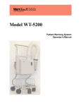
Model WT-5300A
Patient Warming System
Operator’s Manual
To obtain information about a warranty, if any, contact Nellcor’s Technical Services Department
(1.800.635.5267), or your local Nellcor representative.
Contents
5300A Contents
Contents . . . . . . . . . . . . . . . . . . . . . . . . . . . . . . . . . . . . . . . . . . . . . . . . . . . . . . . . . . . . . .i
Figures . . . . . . . . . . . . . . . . . . . . . . . . . . . . . . . . . . . . . . . . . . . . . . . . . . . . . . . . . . . . . . ii
Tables . . . . . . . . . . . . . . . . . . . . . . . . . . . . . . . . . . . . . . . . . . . . . . . . . . . . . . . . . . . . . . . iii
Safety Information . . . . . . . . . . . . . . . . . . . . . . . . . . . . . . . . . . . . . . . . . . . . . . . . . . . . . . 1
Warnings ............................................................................................................... 1
Cautions ................................................................................................................ 2
Introduction . . . . . . . . . . . . . . . . . . . . . . . . . . . . . . . . . . . . . . . . . . . . . . . . . . . . . . . . . . . 3
Intended Use ........................................................................................................ 3
Manual Availability ................................................................................................3
Background Information ........................................................................................ 3
Safety Features .......................................................................................... 4
Customized Warming Therapy ................................................... 4
Automatic Temperature Stepdown ............................................. 4
Automatic Over Temperature Shutdown .................................... 4
Warning Light .............................................................................. 4
HEPA Filter ................................................................................. 4
Wheel Locks ............................................................................... 4
Symbols ................................................................................................................ 6
Description of the Warming System ..................................................................... 7
Installation . . . . . . . . . . . . . . . . . . . . . . . . . . . . . . . . . . . . . . . . . . . . . . . . . . . . . . . . . . . . 9
Cart Installation ..................................................................................................... 9
IV Pole Installation ..............................................................................................10
Patient Bed Installation ....................................................................................... 11
Using the Warming System . . . . . . . . . . . . . . . . . . . . . . . . . . . . . . . . . . . . . . . . . . . . . 13
Power Supply Cord ............................................................................................. 13
Main Power ......................................................................................................... 13
Temperature Control ........................................................................................... 14
Air Filter .............................................................................................................. 15
Self-Supporting Air Hose .................................................................................... 15
Using WarmTouch CareQuilt and CareDrape Blankets ..................................... 15
Routine Maintenance . . . . . . . . . . . . . . . . . . . . . . . . . . . . . . . . . . . . . . . . . . . . . . . . . . 17
Cleaning the Warming System ........................................................................... 17
Other Routine Maintenance ................................................................................ 17
Specifications . . . . . . . . . . . . . . . . . . . . . . . . . . . . . . . . . . . . . . . . . . . . . . . . . . . . . . . . 19
Warming System Specifications ......................................................................... 19
Transport and Shipping in Shipping Container ......................................... 20
Principles of Operation . . . . . . . . . . . . . . . . . . . . . . . . . . . . . . . . . . . . . . . . . . . . . . . . . 21
Control Panel ...................................................................................................... 21
Index . . . . . . . . . . . . . . . . . . . . . . . . . . . . . . . . . . . . . . . . . . . . . . . . . . . . . . . . . . . . . . . 23
WT-5300A
i
Contents
Figures
Figure 1:
Figure 2:
Figure 3:
Figure 4:
Figure 5:
Figure 6:
Figure 7:
Figure 8:
Figure 9:
Figure 10:
ii
Cart Wheel Lock ................................................................................ 5
Model WT-5300A Front View ............................................................ 7
Model WT-5300A Back View ............................................................ 8
Warming System Cart Installation ..................................................... 9
Warming System IV Pole Installation .............................................. 10
Warming System Patient Bed Installation ....................................... 11
Main Power Switch .......................................................................... 13
Low Temperature Light ................................................................... 14
Control Panel .................................................................................. 14
Control Panel .................................................................................. 21
Contents
Ta b l e s
Table 1: WT-5300A Symbols ............................................................................. 6
Table 2: Model WT-5300A Blower Specifications ............................................ 19
Table 3: Model WT-5300A Cart Specifications ................................................ 19
WT-5300A
iii
Blank Page
Safety Information
Warnings
WARNING: Possible explosion hazard. Do not use the WarmTouch® Model
WT-5300A patient warming system in the presence of flammable anesthetic
agents.
WARNING: Possible electrical shock hazard. To reduce the risk of electrical
shock do not remove the back case. Servicing is only to be done by qualified
personnel.
WARNING: Possible electric shock hazard. Grounding reliability can be
achieved only when the warming system is connected to an equivalent socket
marked “HOSPITAL ONLY” or “HOSPITAL GRADE.”
WARNING: Possible fire hazard. Prevent the blanket material from coming
into contact with a laser or an electrosurgical active electrode; rapid
combustion could result.
WARNING: Possible burn hazard. Do not apply heat directly to open
wounds. All patient’s wounds should be covered while using the warming
system.
WARNING: Possible patient burns. Use caution and consider discontinuing
use on patients during vascular surgery when an artery to an extremity is
clamped. Do not apply the warming system to ischemic limbs. This could
possibly cause the patient to be burned.
WARNING: Possible patient burns. Use caution and monitor closely if used
on patients with severe peripheral vascular disease. This could possibly cause
the patient to be burned.
WT-5300A
1
Safety Information
WARNING: Possible patient burns. Do not warm patients with the warming
system hose only. Thermal injury may result. Always attach the hose to a
WarmTouch blanket before providing warming therapy.
WARNING: WarmTouch CareDrapeTM and CareQuilt® blankets are for
single patient use only.
WARNING: MRI scanning. The warming system is not suitable for use
during magnetic resonance imaging (MRI) scanning. The warming system
may affect the MRI image.
WARNING: Continuously monitor the patient's temperature. Reduce the air
temperature or discontinue therapy when normothermia is reached.
Cautions
Caution: Federal (U.S.A.) law restricts the use of the warming system to sale by or
on the order of a physician.
Caution: The warming system is fitted with an air filter; however, airborne
contamination should be considered when using the warming system.
Caution: If the warming system is mounted on the intravenous (IV) pole, it should
be installed with the top of the unit’s handle less than 76 cm (30 inches) above the
floor to prevent the IV pole from tipping over.
Caution: If a malfunction occurs in the warming system, discontinue use. Notify
your sales/service center of the malfunction. Service is only to be done by
qualified personnel.
Caution: The Model WT-5300A should not be operated in the presence of
electromagnetic fields that are greater than 3 Volts/meter. This could cause
shutdown of the Model WT-5300A by the fail-safe function within the equipment.
Caution: Ensure that the patient is dry or the warming system may be ineffective.
2
Introduction
Intended Use
The WarmTouch Model WT-5300A Patient warming system (warming unit and
blanket) is intended for prevention and treatment of hypothermia. For example,
with the surgical patient, the patient in the preoperative holding area, the pregnant
woman who shivers during epidural anesthesia due to hypothermia, or any patient
who is uncomfortable anywhere in the cold critical care environment.
Manual Availability
The most recent revision of this manual is available on the Internet at:
http://www.mallinckrodt.com/respiratory/resp/Serv_Supp/ProductManuals.html
Background Information
There are numerous ways of warming your patient, from cotton blankets to water
mattresses. Research has shown that low temperatures surrounding the patient are
a major factor contributing to hypothermia.1), 2) The warming system covers the
patient with warm air and actively transfers heat across the skin. The result is to
achieve normal thermia.
In creating this warm customized pocket of air around the hypothermic patient, it
is important to note that stagnant air, even if it is warm, does not work as an
effective heat transfer medium. Stagnant air acts as an insulator, preventing the
boundary layer of molecules next to the skin surface from transferring heat.
Forced air warming causes warmed air molecules to flow over cooler skin surface.
It is this active flow of warmed molecules that acts as a heat transfer medium.
With the warming system, air is warmed and delivered into a lightweight blanket
(CareQuilt or CareDrape Blanket) that rests over or under the patient. The
CareQuilt and CareDrape blankets have many small perforations on the
underside that allow air to exit the blanket and surround the patient.
1) Morris RH, Wilkey BR. “The Effects of the Ambient Temperature on Patient Temperature
During Surgery Not Involving Body Cavities.” Anesthesiology 32:102-107, 1970.
2) Morris RH. “Influence of Ambient Temperature on Patient Temperature During
Intra-abdominal Surgery.” Annals of Surgery 173:230-233, 1971.
WT-5300A
3
Introduction
Safety Features
The Warming System is designed to give healthcare professionals more control
over the patient’s core body temperature. There are several safety features of the
warming system which make it safe and appropriate for such use.
Customized Warming Therapy
Clinicians select temperature range setting at the onset of warming therapy to help
ensure the appropriate setting is selected for every patient.
Automatic Temperature Stepdown
The warming system provides a 45-minute temperature stepdown feature. When
in the Boost mode, blower temperature will automatically drop to the high mode
after each 45-minutes of use. The temperature may be reset to the Boost mode by
selecting the Boost temperature on the unit front panel to start another 45-minute
cycle.
Automatic Over Temperature Shutdown
The automatic temperature controller and two back-up systems help to ensure
temperature will not reach excessive levels. If necessary, the back-up systems
automatically turn off the heater and illuminates the warning light. The warming
system heater will start producing heat when the warming system temperature
drops to approximately 34ºC to 37ºC.
Warning Light
When the warning light on the control panel is illuminated, it indicates that one of
the two thermostats has turned off the heater. The reason for the heater turn-off
should be investigated as soon as possible after use.
HEPA Filter
The system's High Efficiency Particulate Air Filter is 99.97% efficient at
0.3-micron particle size.
Wheel Locks
The cart is equipped with two wheel locks. The wheel locks prevent the cart from
moving while in use. The wheel locks must be released when moving the cart.
4
Introduction
Press the wheel lock arm down to lock the wheel. Lift the wheel lock arm to
release the wheel lock. See Figure 1.
Figure 1: Cart Wheel Lock
WT-5300A
5
Introduction
Symbols
The symbols identified in Table 1 are the symbols used on the WT-5300A and all
WT-5300A labeling.
Table 1: WT-5300A Symbols
Attention symbol, consult
accompanying documentation
Temperature Control
Low
(32 °C)
Temperature Control
Medium
(38 °C)
Temperature Control
High
(43 °C)
Temperature Control
Boost
(45 °C for 45 minutes)
I
0
Power On
Power Off
Protection Class I
Protection Type BF
6
Introduction
Description of the Warming System
The WarmTouch Model WT-5300A Patient warming system (Figure 2 and Figure
3), CareQuilt and CareDrape blankets are intended for prevention and treatment
of hypothermia. For example, with the surgical patient, the patient in the
preoperative holding area, the pregnant woman who shivers during epidural
anesthesia due to hypothermia, or any patient who is uncomfortable cold in the
critical care environment.
1 — Hose
4 — Power Cord
2 — Main Power Switch
5 — Hour Meter
3 — Nozzle
6 — Control Panel
Figure 2: Model WT-5300A Front View
WT-5300A
7
Introduction
1 — Over-Temperature Test Port
4 — Warning Label
2 — Bed Hook Bracket
5 — Nozzle Strap with Clip
3 — Filter Cover
6 — Instruction Label
Figure 3: Model WT-5300A Back View
8
Installation
Cart Installation
The warming system is shipped installed on the warming system cart. See
Figure 4. The warming system should not be placed on the cart with the handle
any higher than 61.6 cm (24.25 inches). At this height, the warming system and
cart pass a 10-degree tilt test. Ensure that the three blower cart clamps are tight.
1 — 24.25 inches (61.6 centimeters) (Maximum)
2 — Blower cart clamps
Figure 4: Warming System Cart Installation
WT-5300A
9
Installation
IV Pole Installation
Figure 5 illustrates the installation of the warming system installed on an IV pole.
The warming system should not be installed on the IV pole with the handle higher
than 76 centimeters (30 inches).
1 — 30 inches (76 centimeters) (Maximum)
Figure 5: Warming System IV Pole Installation
10
Installation
Patient Bed Installation
Figure 6 illustrates the installation of the warming system on a patient bed. The
patient rail connectors will fit on bed rails up to 1.4 inches (3.6 centimeters) wide.
1 — Bed Rails 1.4 inches (3.6 centimeters)
Figure 6: Warming System Patient Bed Installation
WT-5300A
11
Blank Page
U s i n g t h e Wa r m i n g S y s t e m
Power Supply Cord
Plug the warming system power cord into a "hospital grade" or suitable mains
outlet.
Main Power
Power is controlled through one main rocker switch located on the front of the
warming system. To begin operation, press the Main Power switch to the ON
position (Figure 7). The Low temperature light on the control panel will
illuminate and the unit will begin to blow air in the low temperature mode. See
Figure 8.
WARNING: No free-hosing. Do not use the blower without a blanket.
Applying heat to a patient directly from the blower nozzle will cause patient
burns.
1 — Main Power Switch
Figure 7: Main Power Switch
WT-5300A
13
Using the Warming System
1 — Low Temperature Light
Figure 8: Low Temperature Light
Temperature Control
The heating temperature is controlled through the panel of buttons. This panel has
four temperature settings:
•
Low
32 °C (89.6 °F)
•
Medium
38 °C (100.4 °F)
•
High
43 °C (109.4 °F)
•
Boost
45 °C (113 °F) for 45 minutes
The temperature settings represent the range of air temperature entering the
blanket. For patients with severe hypothermia requiring rapid warming, select the
Boost temperature setting. To help prevent hypothermia or for treatment of mild
hypothermia, select High, Medium or Low. The selected temperature light will
illuminate. See Figure 9.
Figure 9: Control Panel
14
Using the Warming System
WARNING: The patient must be closely monitored for rewarming.
Vasodilation and possible hypotension can occur. Use good judgment when
selecting a temperature. If unsure of proper setting, consult with the
attending physician.
Air Filter
The warming system contains a HEPA filter rated 99.97% efficient at 0.3-micron
particle size. See Routine Maintenance on page 17 for filter replacement
procedure.
Self-Supporting Air Hose
Air is delivered into the CareQuilt or CareDrape blankets through a
wire-reinforced hose, attached to the warming system.
Using WarmTouch CareQuilt and CareDrape Blankets
WarmTouch CareQuilt and CareDrape blankets come in a range of sizes and
configurations to fit patient’s individual sizes, surgical procedures, and comfort
needs. Follow the instructions provided with all WarmTouch blankets for specific
information concerning their recommended use.
WT-5300A
15
Blank Page
Routine Maintenance
Caution: The institution should follow local governing ordinances and recycling
instructions regarding disposal or recycling of filter and device components or end
of life of the product.
Cleaning the Warming System
Caution: Do not spray, pour, or spill any liquid on the warming system, its
accessories, connectors, switches, or openings in the case.
For surface-cleaning and disinfecting, follow your institution's procedures or:
•
The warming system may be surface-cleaning by using a soft cloth
dampened with either a commercial, nonabrasive cleaner or a solution of
70% alcohol in water, and lightly wiping the surfaces of the monitor.
•
The warming system may be disinfected using a soft cloth saturated with
a 10% solution of chlorine bleach in tap water.
Other Routine Maintenance
Refer to the WT-5300A service manual for routine maintenance procedures that
require a qualified technician to perform.
WT-5300A
17
Blank Page
Specifications
Warming System Specifications
No special transport or storage methods are required for the warming system.
Table 2: Model WT-5300A Blower Specifications
Dimensions:
38 cm x 41 cm x 28 cm
(15 inches x 16 inches x 11 inches)
Weight:
6.8 kgs (15 lbs.)
Power Requirements
120 VAC, 50 - 60 Hz, 10 A
Automatic Temperature
Stepdown (Boost to High
Temperature)
After 45-minutes of continuous use.
Power Supply Cord:
4.26 m (14 feet)
Thermal Protection:
Thermostat (internal): 47 °C - 50 °C
(117 °F - 122 °F)
Ambient Blower Operating
Temperature Range:
18 °C - 28 °C (64.4 °F - 82.4 °F)
Protection Against Ingress of
Fluids:
IEC 60601-1, sub-clause 44.6 for class
IPX0
Protection Class:
1
Protection Type:
B
Table 3: Model WT-5300A Cart Specifications
WT-5300A
Weight
4.6 kg (10.1 pounds)
Height with Handle Extended
87.6 cm (34.5 inches)
Height with Handle Retracted
70.5 cm (27.8 inches)
Width
31.8 cm (12.5 inches)
Depth
38.6 cm (15.2 inches)
19
Specifications
Transport and Shipping in Shipping Container
20
Temperature
-40ºC to 70ºC (-40ºF to 158ºF)
Altitude
-390 m to 6,096 m (-1,280 ft to 20,000 ft)
Barometric Pressure
1,060 hPa to 500 hPa (375 mmHg to 795 mmHg)
Relative Humidity
15% to 95% (non-condensing)
Principles of Operation
Principles of Operation
Control Panel
The control panel features four manually switched temperature settings. The
selected temperature is indicated by an LED indicator.
Figure 10: Control Panel
Each temperature setting represents the average temperature of air entering the
blanket. The four temperature settings are:
•
Low
32 °C (89.6 °F)
•
Medium
38 °C (100.4 °F)
•
High
43 °C (109.4 °F)
•
Boost
45 °C (113 °F) for 45 minutes
There is a warning light on the control panel. See Figure 10. The warning light
indicates that the warming system’s safety thermostats have disabled the heater.
The warming system will continue to blow air until the output temperature has
decreased below the thermostat threshold temperature of 50 ºC. If there is no
malfunction in the warming system, it should function normally. If the warning
light illuminates again, the blower should be replaced and the faulty blower
should be checked by qualified hospital personnel.
WT-5300A
21
Blank Page
Index
A
M
Air filter 15
Air hose 15
Automatic shutdown 4
Main power 13
Main power switch 13
MRI warning 2
B
P
Bed installation 11
Burn hazard 1
Patient bed installation 11
Patient burns 1
Possible explosion hazard 1
Power supply cord 13
Principles of operation 21
C
CareDrape 15
CareQuilt 15
Cleaning 17
Control panel 14, 21
Customized warming therapy 4
D
Disinfecting 17
E
Electric shock 1
Electrical shock hazard 1
Explosion hazard 1
F
Fire hazard 1
I
Introduction 3
IV pole installation 10
WT-5300A
R
Routine maintenance 17
S
Safety features 4
Safety information 1
Single patient use 2
Specifications 19
Surface cleaning 17
T
Temperature control 14
U
Using the warming system 13
W
Warning light 4
Warnings 1
23
Blank Page
Tyco Healthcare Group LP
Nellcor Puritan Bennett Division
4280 Hacienda Drive
Pleasanton, CA 94588 USA
Toll Free: 1.800.635.5267
© 2006 Nellcor Puritan Bennett Inc.
All rights reserved.
Manufactured in the U.S.A.
P/N 10017812A-1206