1
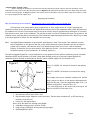
Magnum (Roller Hydraulic Cams) Before removing the distributor, mark the base and the intake with “witness” marks so that the distributor can be reinstalled correctly. Keep in mind that the distributors in Magnum truck applications DO NOT control the spark timing and cannot be “timed” with timing light. All Magnum hydraulic roller lifters need 2 turns (.080”) of pre-load. Roller cams do not require a breakin or spring changes like flat tappet cams. Degreeing the camshaft Why you should degree the camshaft? We want this cam to run the best it can, you should too!! You’ve spent a lot of money and are going to spend a lot of time—might as well do it right. Degreeing the camshaft correctly with a dial indicator and degree wheel tells you that all the components that control the position of the camshaft are accurate. Just because many of the parts are new, does not guarantee they will degree-in accurately with the other parts, such as the crankshaft. The only way to know is to check. Checking the center-line position of the camshaft can be confusing due to the similarity of the terms lobe separation angle and center-line. We will try to make it as easy as possible to center-line the camshaft the correct way. Note: All Hughes Engines camshafts are ground with some advance in them. This means if the camshaft is centerlined or degreed-in to the specs on the cam card it will be advanced to match whatever the cam card says is ground into it. However, this does not mean if you install the sprockets “dot-to-dot” it will be advanced properly. It should be, but you don’t know for sure unless you check it. (You do not need to enter the degrees of advance into any of your calculations. It is already figured in.) The lobes on Hughes Engines Inc. are non-symmetrical. A non-symmetrical lobe will have a different center-line when checked at 0.050” above the base circle than it does when checked at the top of the lobe. Hughes Engines Inc. camshafts must be checked at the bottom of the lobe, which is 0.050” tappet lift off the base circle. Figure 1 Point B Rotation "X" Point A Base Circle Point “A” is 0.050” off the base circle and is the opening point. Point “B” is 0.050” off the base circle and is the closing point. For example, let’s say our camshaft is advanced 4 and will have a center-line that is 4 less than the lobe separation angle. In this case, if the lobe separation angle is 111, a 4 advance would be 107 centerline (111-4) “X” is the difference of the center-line at the top of the lobe vs. at 0.050” off the base circle. Tools required or that make the job a lot easier 1. Dial indicator with at least .500” travel 2. Degree wheel (Larger diameter is more accurate). The best ones are marked 0º to 90º and then go backward from 90º to 0º. 3. Pointer for the degree wheel Note: All of the above are included in kit #8346 4. Crankshaft turning tool p/n 4799 or 67493 5. Height mike p/n 8338 for setting valve spring heights 6. Burnishing Ball p/n 8319 Page 4