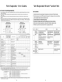
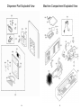
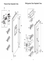
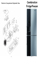
1
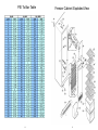
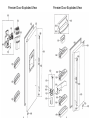
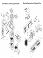
Engineers Quick
Reference Guide
Produced by:
Kam Pankhania
Senior White Goods Technical Engineer
LG Electronics UK Ltd,
Registered Office: LG House, 250 Bath Road, Slough, Berkshire, SL1 4DX / Registered
No: 2143888
This book has been provided for LG Electronics UK
Ltd approved service companies and engineers as a
reference guide only. Please take note of the
Warnings and precautions for Safety As LG
Electronics UK Ltd cannot accept any responsibility
for accidents, injuries or fatality when working on our
products.
If you are not an approved LG repair Company or
Engineer please do not attempt any service other
than any suggestions in your owners manual and
kindly return this booklet to the address printed on
the Back cover.
We would like to encourage you to use this Guide
out in the field and hope you find it a useful tool.
Should you wish to update your product knowledge
we have training modules available at
http://www.lgsvc-academy.com/
For the very latest updates and information on LG
products, please visit service bulletins please visit
the LG website http://eic.lgservice.com/ . All website
User ID and Passwords can be obtained from your
service company.
Please see the contacts pages on the back cover
should you need further support.
We would also like to encourage any feedback, and
should you have any further suggestions please do
not hesitate to contact me at
[email protected].
On Behalf of LG Electronics UK Ltd. We thank you
for your hard work, support and care you put into
repairing our customers products.
We recommend a minimum of 2 Megger Ohms on earth insulation
testing and a maximum of 0.25 Ohms for earth continuity tested.
At LG Electronics we take engineer & customer safety very seriously
and work within the legal electrical guidelines without compromise.
We therefore require that all engineers carry the correct and
calibrated testing equipment for electrical safety testing on all our
products and record the readings on the job sheet.
Contents
Key Engineering Steps to Repair Service
1. Confirm all appointments for that day with guide ETA
Key Steps To Repair
Side by Side Refrigeration
Twin Evaporator Refrigeration
Non-Plumbed Refrigeration
Combination Refrigeration
Top 50 Refrigeration parts Used
Refrigeration FAQ
Washing Machine
Steam Washer
11KG Fixed Tub washing machine
Fixed Tub Steam Washer Dryer
Washer/Dryer
Top 50 Laundry parts Used
Smart Diagnostics
Laundry FAQ
Condenser Dryer
Condenser dryer FAQ
Dishwasher
Dishwasher FAQ
GSFS
Notes
Contacts & Support
1
2-16
17-25
26-34
35-46
47-48
49
50-59
60-75
76-97
98-106
107-116
117-118
119-120
121
122-134
135
136-155
156-157
158-177
178-182
183
2. When calling re-confirm the fault and check availability of
any spare parts that may be needed.
3. Call The customer if delayed prior to appointment time
explaining reason for delay and give new ETA
4. Dress appropriately and look professional
5. When meeting the customer have a friendly Introduction
showing your ID card
6. Listen to the customers Fault description
7. Check model Serial and proof of purchase
8. Carry out repair & check for any other faults with unit
9. Clean up after repair
10. Demonstrate the product working after repair
11. Advise customer on product care & maintenance
12. Leave customer with job receipt and say goodbye
13. Put in a detailed report including any parts used.
In the Event of parts required to be ordered
1. Fully explain any work that has been done
2. Explain what parts are needed giving a rough ETA
3. Provide your office phone number
4. Place ‘purchase order’ same day to office
5. Chase parts and update customer if no parts have been
received in 5 days.
1
SxS Refrigeration
2
SxS Error Codes
3
4
5
6
6
7
7
PSI To Bar Table
8
Freezer Cabinet Exploded View
9
Ice & Water Exploded View
10
Fridge Cabinet Exploded View
11
Freezer Door Exploded View
12
Freezer Door Exploded View
13
Refrigerator Cabinet Exploded View
14
Machine Compartment Exploded View
15
Dispenser Exploded View
16
Twin Evaporator SxS
17
Twin Evaporator Error Codes
18
Twin Evaporator Micom Function Test
19
Freezer Cabinet Exploded View
20
Refrigerator Cabinet Exploded View
21
Refrigerator Door Exploded View
22
Freezer Door Exploded View
23
Dispenser Part Exploded View
24
Machine Compartment Exploded View
25
Non Plumbed SxS
26
Non Plumbed Error Codes
27
New Non Plumbed Error Codes
28
Freezer Cabinet Exploded View
29
Refrigerator Cabinet Exploded View
30
Dispenser Exploded View
31
Freezer Door Exploded View
32
Refrigerator Door Exploded View
33
Machine Compartment Exploded View
34
Combination
Fridge/Freezer
35
Combination Error Codes
36
37
Cabinet Exploded View
38
39
Door & Interior Exploded View
40
Water Tank Assembly Exploded View
41
Combination Model Type
GR389/399 Error Codes
42
Cabinet Exploded View
15
43
Combination Model Type GR419
Error Codes
44
Combination Model Type
GCB399 Error Codes
45
Top 50 Refrigeration Parts Used
Model GR419***
No
1
2
3
4
5
6
7
8
9
10
11
12
13
14
15
16
17
18
19
20
21
22
23
24
25
46
Parts No
5231JA2012A
ADQ32617703
5433JA1152C
AHA72909001
AEQ32381001
4838JA1004A
MJX57763201
AJU30690301
AHT65058003
EAU35507301
AJP31573002
AJL30690601
3650JQ1054D
MCD61866801
AJL72992401
AJU72909901
6615JB2002R
MCD61866802
6421JB2002B
MCD61866803
AJP31574406
ADD72909637
AED36768606
ADX31571022
6912JB2008A
Product Item Description
RF
Filter Assembly,Water
RF
Filter Assembly,Water
RF
Door Foam Assembly,Home Bar
RF
Pump Assembly
RF
Ice Maker Assembly,Kit
RF
Tank,Water
RF
Valve,Water
RF
Valve Assembly,Water
RF
Shelf Assembly,Refrigerator
RF
Motor,AC
RF
Tray Assembly,Vegetable
RF
Tank Assembly,Water
RF
Handle,Decor
RF
Connector,Tube
RF
Tank Assembly,Water
RF
Valve Assembly,Water
RF
Controller Assembly
RF
Connector,Tube
RF
Solenoid,Reversing,Valve
RF
Connector,Tube
RF
Tray Assembly,Drawer
RF
Door Foam Assembly,Refrigerator
RF
Handle Assembly
RF
Gasket Assembly,Door
RF
Lamp,Incandescent
47
Mapping Model Code
GR-267EHF
GR-267EHF
GR-267EHF
GWL227HSYA
GR-267EHF
GR-267EHF
GWL227HSYA
*R-151SF
GW-B207FLQA
GR-267EHF
GR-267EHF
*R-151SF
GR-267EHF
GR-P247CNPV
GCF-3923AC
GWL227HSYA
GW-B207FSQK
GR-P247CNPV
GR-267EHF
GW-P209FQA
GR-267EHF
GWL227HBYA
GWL207FBQA
GW-B207FLQA
GR-267EHF
Refrigeration FAQ’s
26
27
28
29
30
31
32
33
34
35
36
37
38
39
40
41
42
43
44
45
46
47
48
49
50
EBE60661302
3651JA2266E
5300JB1092B
TCA30071901
3581JQ2003A
5210JA3004A
ADD72909636
MBL62621606
4932JA3002A
4975JQ1005B
5989JA1002K
3650JQ2035D
ADX31571025
AHT65058006
3219JA3001E
4932JA3009C
6912JB2004L
AJL73051901
AKC32375401
3550JA1495A
5421JA1124F
ADX62799509
5005JA1008N
5005JQ1007G
5220JA2008A
RF
RF
RF
RF
RF
RF
RF
RF
RF
RF
RF
RF
RF
RF
RF
RF
RF
RF
RF
RF
RF
RF
RF
RF
RF
Solenoid Assembly
Handle Assembly,Freezer
Heater,Sheath
Compressor,Set Assembly
Door Assembly,Freeze Room
Tube,Plastic
Door Foam Assembly,Refrigerator
Cap,Screw
Connector,Tube
Guide Assembly,Rail
Ice Maker Assembly,Kit
Handle,Decor
Gasket Assembly,Door
Shelf Assembly,Refrigerator
Tube Assembly,Wire Condensor
Connector,Tube
Lamp,Incandescent
Tank Assembly,Water
Bucket Assembly,Ice
Cover,Lamp
Evaporator Assembly
Gasket Assembly,Door
Basket Assembly,Door
Basket Assembly,Door
Valve,Water
48
GW-L227HSYZ
GR-267EHF
GR-267EHF
GR-267EHF
GR-267EHF
GR-267EHF
GWL227HSYA
GCD-3922NS
GR-267EHF
GR-267EHF
GW-L207FLQV
GR-267EHF
GWB207FBQA
GW-L227BTQV
GR-L207EQ
GR-F218JTTA
GR-267EHF
GS7161STAV
GR-267EHF
GR-267EHF
*R-151SF
GR-267EHF
GR-267EHF
GR-267EHF
GR-267EHF
Q. What is the correct temp to set Freezer and Fridge?
A. Preferred Setting is -21deg for freezer and 3-4 deg.
Q. Frosting up in the Freezer?
A. Door is left ajar for a long period of time or door seal is not sealing
properly
Q. Freezer door opening when shutting fridge door on combination
fridge freezer?
A. Freezer door not closed properly, obstacle stopping it from closing ie:
Icemaker mould on top shelf remove and place on bottom shelf.
Q. Freezer not cooling properly?
A. Blocked or dirty vent at the rear ventilation or an iced up evaporator
Q. Where to set vegetable drawer setting (High or Low)?
A. High for vegetables and low for meat.
Q. Ice not dispensing?
A. Jammed ice in the ice box or auger motor weak.
Q. Not producing ice?
A. Icemaker may be switched off, or ice maker may need resetting, or
no water supply.
Q. Food in the fridge all frozen?
A. Check the damper and also if the temperature setting too cold.
Q. Noisy when fridge is operating?
A. Suction pipes vibrating or freezer fan jammed up with ice.
Q. No water coming out from dispenser or neither making ice?
A. Water tank empty or air lock in the water pipes.
49
Washing Machine
50
All Washing Machine Error Codes
51
CD - can last up to 4 hours, CD (washer/dryer only) means the cloths have
finished drying and you can switch the machine off even though CD is
displayed. The door will release 2 minutes after that. If clothes come out
wet then it means that customer has put more then half load in. In all washer
dryers half load needs to be taken out.
The washing machine does wash and go straight to dry if you set it that way,
this feature is there as it assumes you have put a half load in and you want to
do a wash and dry.
52
53
QC Test Mode
Some machines require: pressing of Option (left), Rinse and power to
enter test mode
54
55
Cabinet Assembly Exploded View
Some machines require the following to Check
water level frequency
56
57
Control Panel & Dispenser
Exploded View
58
Drum & Tub Assembly Exploded View
59
Steam Washer
60
QC Test Mode
61
How Steam Works
62
63
Disassembly
64
65
66
67
68
69
70
71
Cabinet Assembly Exploded View
72
73
Control Panel & Dispenser
Exploded View
74
Control Panel, Dispenser & Steam
Generator Exploded View
75
11kg Fixed Tub Washing
Machine
76
Specification & Parts Identification
77
78
79
80
81
82
83
QC Test Mode
84
85
86
87
Disassembly
1.
Disassemble lower case assembly.
Required tool: (+) Electric driver
2.
3.
4.
Disassemble of main PWB assembly.
Disconnect the wiring connector.
First , press hook and turn the safety,
switch assembly, switch assembly
safety.
Unscrew from the base.
1.
Disassemble of top plate
assembly.
2.
Remove 6 screws between back
cover and side cabinet.
3.
Remove 4 screws connected to
back cover with base cabinet.
4.
Remove 2 screws, between back
cover and tub outer.
5.
Remove 2 screws for fixing drain
hose holder.
6.
Remove 4 screws from Inlet valve
and AG.
7.
Remove 2 earth screws from
back cover.
8.
Disassembly 3 holder hooks for
fixing harness.
9.
Disassemble the red connector
on the noise filter.
10. Pull out drain house from the
back cover.
88
89
1.
Disassemble back cover .
3.
Remove the large and small rear
gasket clamp buy using the
clamp jig.
4.
Unscrew the rear suspension nut.
5.
Unscrew the bolt between the
bearing housing and rear
suspension.
7.
8.
90
Disassemble of top plate assembly.
2.
Disassemble control panel
assembly.
3.
Disassemble lower cover.
4.
Disassemble cabinet cover.
5.
Disassemble front gasket clamp by
using clamp jig.
6.
Take out gasket hole parts from the
hook of the tub cover (direction
of:11:00, 9:00, 7:00, 6:00, 5:00, 3:00
and 1:00 o’clock).
7.
Take out front gasket upper rib in dry
duct hole of tub cover.
8.
Disassemble front gasket.
Disassemble of top plate
assembly.
2.
6.
1.
Disassemble the rear
suspension.
Remove 8 screws, on both
weight brackets.
Disassemble rear gasket.
91
Required tool: 12,13mm Spanner (+) Electric driver
1.
2.
3.
Disassemble the right side of the
cabinet.
Remove 2 damper pins from the
damper bracket and base holder.
1.
Disassemble the top plate assembly.
2.
Remove 8 screws, right side of back cover.
3.
Disassemble control panel assembly.
4.
Disassemble lower cover.
5.
Disassemble cabinet cover.
6.
Remove the earth screw on the right side of the
cabinet.
Disassemble friction damper.
Bracket (Right)
1.
92
The Disassemble the right side of
the cabinet.
2.
Disassemble a nut (Suspension –
Base Cabinet).
3.
Remove suspension bolt.
4.
Disassemble suspension.
1.Remove 4 screws on the damper
bracket.
2.Disassembly of damper bracket.
93
Cabinet Assembly Exploded View
Required tools: Nipper, Cable tie, (+) Electric driver
1.
The back cover is disassembled.
2.
Remove the cable tie.
3.
Disassemble vibration sensor assembly.
94
95
Control Panel & Dispenser
Exploded View
96
Drum & Tub Assembly Exploded View
97
Fixed Tub Stream
Washer Dryer
98
Program Chart
99
QC Test Mode
100
101
Cabinet Assembly Exploded View
102
103
Control Panel & Dispenser
Exploded View
104
Drum & Tub Assembly Exploded View
105
Dryer Duct Assembly Exploded View
106
Washer Dryer
107
Main PCB Layout
108
Power PCB Layout
109
Program Chart
110
QC Test Mode
111
Cabinet Assembly Exploded View
112
113
Control Panel & Dispenser
Exploded View
114
Drum & Tub Assembly Exploded View
115
Top 50 Laundry Parts Used
Dryer Assembly Exploded View
No
1
2
3
4
5
6
7
8
9
10
11
12
13
14
15
16
17
18
19
20
21
22
23
24
25
116
Parts No
4925ER1002D
4681EA2001E
4036ER2004A
383EER3001G
EBR65873626
AEG33121503
MDS38265303
3045ER1002A
4620ER4002B
3045ER0002A
4774FR3118B
4036ER4001A
4901ER2003A
6601ER1001B
MDS41955002
4413ER1001D
4417EA1002G
MFE38265101
ACZ34745501
3108ER1001A
MDS38265301
4986ER1005C
4681EA2001A
6601ER1001A
4432EN2005A
Product
WM
WM
WM
WM
WM
WM
WM
WM
WM
WM
WM
WM
WM
WM
WM
WM
WM
WM
WM
WM
WM
WM
WM
WM
WM
Item Description
Dispenser Assembly
Motor Assembly,AC,Pump
Gasket
Parts Assembly
PCB Assembly,Main
Heater Assembly
Gasket
Tub Assembly,Drum(Inner)
Stopper,Leg
Tub Assembly,Outer
Hinge
Gasket
Damper Assembly,Friction
Switch Assembly,Locker
Gasket
Rotor Assembly
Stator Assembly
Lifter
Dispenser Assembly
Casing,Pump
Gasket
Gasket
Motor Assembly,AC,Pump
Switch Assembly,Locker
Lifter
117
Mapping Model Code
F1402FDS
F14853WHS
F14853WHS
WD-14318FDK
F1443KD
F14853WHS
F1402FDS
WD-1465FD
WD-14370FD
WD-1465FD
F14853WHS
F14853WHS
F1402FDS
WD-1465FD
F14853WHS
F14853WHS
F14853WHS
F14853WHS
F14853WHS
F14853WHS
F1403FDS
F1056QD1
F1402FDS
WD-1465FD
F1402FDS
Smart Diagnostics
26
27
28
29
30
31
32
33
34
35
36
37
38
39
40
41
42
43
44
45
46
47
48
49
50
5220FR1251E
3045ER0026D
4986ER1005A
4986ER1006A
1TTG0403218
3650ER3002B
6871ER1081Q
EBR52361602
4417EA1002D
5214FR3188G
6871ER1009F
6871ER1081F
MDS62012602
4681EA2002F
6601ER1005A
4432ER1003A
5301ER1001B
MDS55242602
4986ER1003B
6501KW2001A
MFE57764501
3212ER1004B
4925ER1012A
4036EN4002A
4400EL1001A
WM
WM
WM
WM
WM
WM
WM
WM
WM
WM
WM
WM
WM
WM
WM
WM
WM
WM
WM
WM
WM
WM
WM
WM
WM
Valve Assembly,Inlet
Tub Assembly,Outer
Gasket
Gasket
Screw,Tapping
Handle
PCB Assembly,Main
PCB Assembly,Main
Stator Assembly
Hose,Pump
PCB Assembly,Main
PCB Assembly,Main
Gasket
Motor Assembly,AC,Pump
Switch Assembly,Locker
Lifter
Heater Assembly
Gasket
Gasket
Sensor Assembly
Lifter
Frame,Door(Inner)
Dispenser Assembly
Gasket
Belt,Poly V
118
F1402FDS
F14853WHS
F1402FDS
F1402FDS
F1403YD6
F1402FDS
F1402FDS
F1247TD
F1403FDS
F14853WHS
F1402FDS
F1402FDS
F1443KD
F1402FDS
F1402FDS
WD-1465FD
F1402FDS
F14733WH
WD-16336FDK
F14853WHS
DD147MWB
WD-1465FD
WD-12361TDK
F1402FDS
TD-C70044E
How to use:
119
Laundry FAQ
Example:
Q. Black or gray marks on clothes after washing.
A. There is a lack of service wash and/or under dosing of detergent
Q. Machine will not go to spin properly and is sticking on 9 or 12min.
A. The machine is not spinning as the machine will need more load balance out
and spin. Also check the unit is level on a solid floor.
Q. Scraping metal sound during was cycle
A. check rear cover for dents or possible bra wire in the drum.
Q. Ripping clothes or swallowing small items of clothes in between the drum.
A. Gap between door seal and inner drum too big, replace door seal
Q. Clicking sound during wash and spinning cycle.
A. Check for loose or warn dampers and damper pins.
Q. Washer drier shutting down after approx 10min during drying cycle
A. check drier fan for obstacle and also clean condenser fully.
Q. Loud knocking sounds during fast spin.
A. Check for loose counter weight and tightened them.
Q. Bleep sound has disappear when selecting program and also when its
finished.
A.A possible power cut can cause this, read operating manual how to switch
bleep back on.
Q. Door seal lip ripped off.
A. Clothes were left hanging on door seal when door were shut. Advice customer
to make sure the all clothes are pushed into the drum before shutting door.
Q. Machine turns on/off on its own during cycle or switching on while
machine is not in use.
A. check for warped main PCB on the control panel. Fit a small washer on the
screw on the Right hand side that is holding the PCB in place to straighten it out.
Agent books an engineer
with all diagnostics details.
120
121
Condenser Dryer
122
Error Codes
123
124
125
126
127
128
129
Control Panel & Top Plate Assembly
130
131
Cabinet Cover & Door Assembly
132
Base & Motor Assembly
133
Back Cover & Drum Assembly
Condenser Dryer FAQ
Question
What to do
Dryer doesn't work
1. Check dryer is plugged in
2. Check "Start" button is pressed.
3. Check door is properly closed.
4. Check Room temperature is below 5℃
5. Check maintenance flap is properly closed.
6. Check a fuse is not blown or the circuit breaker is tripped and repla
1. Filter should be cleaned after each load
2. Check water container emptied
3. Check cleanness of condenser
4. Check to select correct program setting for fabric type.
5. Check air intake grille or rear vents of the dryer to be obstructed.
6. Check the c
It takes a long time to dry
"Empty filter"lamp flashes
1. Check filter is cleaned
2. Cleck condenser unit is clogged
Drum light does not work
1. Check On/Off button is pressed.
Clothes have lots of lints
1. Check lint filter is empty
2. Check dryer has only clean items
3. Check laundry is properly sorted in the drum
4. Check laundry is overloaded.
5. Check there was any paper, tissue,or similar item in the pockets of laundry
The drying time is not consistent
The drying time for a load will vary depending on the heat setting, the size of the load, the
type of fabrics, the wetness of the clothes and the condition of the exhaust ducts and lint
filter.
Water is leaking
1. Check the door and maintenance flap seals are dirty and damaged.
The clothes are wrinkled
Check laundry is overloade. Try a shorter drying time and remove items while they still
retain a slight amount moisture.
To avoid shrinkage, please carefully follow the care and use instructions for your
garment, because some fabrics will naturally shrink when washed. Other fabrics
can be washed but will shrink when dried in a dryer.
The clothes shrinked
134
135
Dishwasher
136
QC Test Mode
137
Error Codes
138
139
140
141
142
143
144
145
146
147
148
149
Top Plate & Side Panel
150
Cabinet Assembly
151
Door Assembly
152
Base Assembly
153
Sump Assembly
154
Basket Assembly
155
Dishwasher FAQ’s
The washing results are not satisfactory
Dishwasher is not Draining
Dishwasher is leaking
156
157
Using GSFS
How To Check For Service Bulletins
http://gsfs-eu.lge.com
Log on
User ID & password can be obtained from your Head
office
Click on ‘More’ button’
158
159
How To Download a Service Manual
Click on ‘More’ button’
Log on
User ID & password can be obtained from your Head
office
Results will be
displayed as seen
Click on
‘Inventory’ and
then ‘Parts
Portal’
160
161
Click on ‘Model’ box.
Type in the first 3 letters & press ‘Return/Enter on your keyboard. Scroll down until you find
model then Click on the required model to select and then click on ‘Inquiry’.
162
163
How To Find A Part Number
Select exploded view
Click on
‘Technical Pack’
Log on
(User ID & password can be obtained from your Head office)
Click on
‘Inventory’, Then
‘Parts Portal’
Click on ‘Model’
Type in first 3 letters and press ‘Return’
Scroll down until you find model
Now click on ‘Inquiry’
164
165
Select HTML
How To Find Price & Availability
Scroll down on the right until you find part number
(If you cannot find part Click on ‘Exploded View’)
Log on
(User ID & password can be obtained from your Head
office)
1. Click to make page full size
4. To view next page
Go to inventory and then click on ‘Parts Portal’
2 .Click ‘Search’
3. Click on location number to obtain the part number
166
167
1.
2.
Type part number into
part number box
Press ‘Enter’ (Do not click
on Inquiry)
3. Wait until part description comes up
Original part
4. Now click on ‘Inquiry’
Alternative part
Availability of part
5. Double click on the
Green line
Price of part
Click on ‘OK’
168
169
How To Cancel A Part from an Order
Click on ‘Parts Order Status’
Log on
User ID & password can be obtained from your Head
office
Date from
Click on ‘Inventory’
Change Search Condition
Enter POE number
Amend order dates
Click ‘Inquiry’
170
171
Date to
Click on the part number you require from order
Input cancel reason and input name to confirm who
cancelled the part.
Click on ‘Request’
Click ‘OK’ to confirm cancellation
Click on ‘Cancel Request’ and above pop up box will
appear
172
173
How To Cancel A Part from an Order
Cancellation is now complete
Log on
User ID & password can be obtained from your Head
office
Select
1. Inventory
2. Parts Order Status
If the above pop up box appears, the part cannot be
cancelled as the part has already been picked or the
is on hold. In such instances please contact:
[email protected]
174
175
Double click ‘Tracking No’
Select
1. Search Condition
Choose
Order No for POE ref
or
Customer Order No for your ref (6xxxxxxx)
2.
Order Date
Change date range
3. Click ‘Inquiry’
This shows Status of your order
Please see for Details
Click ‘Delivery Tracking’
176
177
Notes
……………………………………………
……………………………………………
……………………………………………
……………………………………………
……………………………………………
……………………………………………
……………………………………………
……………………………………………
……………………………………………
……………………………………………
……………………………………………
……………………………………………
……………………………………………
……………………………………………
……………………………………………
……………………………………………
……………………………………………
……………………………………………
……………………………………………
……………………………………………
……………………………………………
……………………………………………
178
Notes
……………………………………………
……………………………………………
……………………………………………
……………………………………………
……………………………………………
……………………………………………
……………………………………………
……………………………………………
……………………………………………
……………………………………………
……………………………………………
……………………………………………
……………………………………………
……………………………………………
……………………………………………
……………………………………………
……………………………………………
……………………………………………
……………………………………………
……………………………………………
……………………………………………
……………………………………………
179
Notes
Notes
……………………………………………
……………………………………………
……………………………………………
……………………………………………
……………………………………………
……………………………………………
……………………………………………
……………………………………………
……………………………………………
……………………………………………
……………………………………………
……………………………………………
……………………………………………
……………………………………………
……………………………………………
……………………………………………
……………………………………………
……………………………………………
……………………………………………
……………………………………………
……………………………………………
……………………………………………
……………………………………………
……………………………………………
……………………………………………
……………………………………………
……………………………………………
……………………………………………
……………………………………………
……………………………………………
……………………………………………
……………………………………………
……………………………………………
……………………………………………
……………………………………………
……………………………………………
……………………………………………
……………………………………………
……………………………………………
……………………………………………
……………………………………………
……………………………………………
……………………………………………
……………………………………………
180
181
Notes
……………………………………………
……………………………………………
……………………………………………
……………………………………………
……………………………………………
……………………………………………
……………………………………………
……………………………………………
……………………………………………
……………………………………………
……………………………………………
……………………………………………
……………………………………………
……………………………………………
……………………………………………
……………………………………………
……………………………………………
……………………………………………
……………………………………………
……………………………………………
……………………………………………
……………………………………………
182
Contacts & Support
Engineers Tech Support :
0844 847 1402 (option 2)
Spares Support:
0844 847 1402 (option 1)
Spares Email:
[email protected]
Engineers Website:
Http://eic.lgservice.com
Warranty Claims:
[email protected]
Customer Information Centre:
0844 847 5454
Customer website:
www.lg.com
183