1
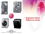
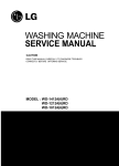
website :http://biz.lgservice.com
e-mail : http://LGEservice.com/techsup.html
WASHING MACHINE
SERVICE MANUAL
CAUTION
READ THIS MANUAL CAREFULLY TO DIAGNOSE TROUBLES
CORRECTLY BEFORE OFFERING SERVICE.
MODEL : WD-1409RD(1~9)/WDP1103RD(1~9)/WM3455H*
P/No.: MFL30574764
51
CONTENTS
1. SPECIFICATIONS ............................................................................................................................. 3
2. FEATURES & TECHNICAL EXPLANATION ..................................................................................... 4
3. PARTS IDENTIFICATION ................................................................................................................. 6
4. INSTALLATION .................................................................................................................................. 7
5. OPERATION ................................................................................................................................... 12
6. WIRING DIAGRAM / PCB LAYOUT / PROGRAM CHART ............................................................ 14
7. TROUBLESHOOTING ......................................................................................................................18
7-1.BEFORE PREFORMING SERVICE ......................................................................................... 18
7-2.LOAD TEST MODE .................................................................................................................. 18
7-3.HOW TO KNOW THE WATER LEVEL FREQUENCY ............................................................. 19
7-4.HOW TO KNOW TO TEMPERATURE OF EACH THERMISTOR AT OPERATING CONDITION .. 19
7-5.ERROR DISPLAY ..................................................................................................................... 20
7-6.TROUBLESHOOTING WITH ERROR ..................................................................................... 21
• IE (Water Inlet Error) .............................................................................................................. 21
• UE (Unbalanced Error) ........................................................................................................... 22
• OE (Water Outlet Error) .......................................................................................................... 23
• FE (Flow over Error) ............................................................................................................... 25
• PE (Pressure Sensor S/W Error) ............................................................................................ 26
• DE (Door open Error) ............................................................................................................. 27
• tE (Thermistor (Heating) Error) ............................................................................................... 28
• LE (Motor Lock Error) ............................................................................................................. 29
• DHE (Dry Heater Error) .......................................................................................................... 31
• Dry Heater Trouble ................................................................................................................. 32
• Dry Fan Motor Trouble ............................................................................................................ 33
8. TROUBLESHOOTING ELSE .......................................................................................................... 34
• No Power ................................................................................................................................ 34
• Vibation & Noise in spin ......................................................................................................... 35
• Detergent & Softener does not flow in .................................................................................... 36
• Water Leak ............................................................................................................................. 37
9. DISASSEMBLY INSTRUCTIONS ................................................................................................... 39
10. EXPLODED VIEW ......................................................................................................................... 47
2
1. SPECIFICATION
ITEM
WD-1409RD(1~9)/WDP1103RD(1~9)/WM3455H*
POWER SUPPLY
127V~, 60Hz
PRODUCT WEIGHT
72kg
WASHING
140W
SPIN
440W
ELECTRICITY
DRAIN MOTOR
30W
CONSUMPTION
STEAM HEATER
1100W
WASH HEATER
2000W
DRY HEATER
1500W
WASH
50rpm
SPIN
No Spin/400/800/1000/1400
REVOLUTION
SPEED
OPERATION WATER PRESSURE
1.0-8bar (100-800kPa)
CONTROL TYPE
Electronic
WASH & DRY CAPACITY
Refer to the Rating Label
DIMENSION
600mm(W)x640mm(D)x850mm(H)
WASH PROGRAM
Cotton, Cotton Quick. Synthetic, Delicate, Hand Wash,Wool,
RINSE
Quick30, Duvet, Baby Care
Rinse+Spin, Rinse+, Normal+Hold
DOOR SWITCH TYPE
Bi-Metal type
WATER LEVEL
10 steps (by sensor)
RESERVATION
From 3 hours to 19 hours
SENSING OF THE LAUNDRY AMOUNT
Adapted
FUZZY LOGIC
Adapted
DISPLAY OF THE REMAINING TIME
Adapted
ERROR DIAGNOSIS
10 items
POWER AUTO OFF
Adapted
CHILD LOCK
Adapted
AUTO RESTART
Adapted
TIME SAVE
Adapted
3
2. FEATURES & TECHNICAL EXPLANATION
2-1. FEATURES
Direct Drive System
The advanced Brushless DC motor directly drives the drum without belt and pulley.
Water Circulation
Spray detergent solution and water over the load over continu.
Clothes are soaked more quickly and thoroughly during wash cycle.
The detergent suds can be removed more easily by the water shower during rinse cycle.
The water circulation system uses both water and detergent more efficiently.
Built-in Heater
Internal heater automatically heats the water to the best temperature on selected cycles.
Child Lock
The Child lock prevents children from pressing any button to change the settings during
operation.
More economical by Intelligent Wash System
Intelligent Wash System detects the amount of load and water temperature, and then
determines the optimum water level and washing time to minimize energy and water
consumption.
Low noise speed control system
By sensing the amount of load and balance, it evenly distributes load to minimize the
spinning noise level.
Automatic Wash Load Detection
Automatically detects the load and optimizes the washing time.
4
2-2. DETERMINE WASHING TIME BY FUZZY LOGIC
To get the best washing performance optimal time is determined by sensing of water temperature,
selected washing temperature and laundry amount.
water
temperature
washing time
selected
washing
temperature
FUZZY
LOGIC
rinse time
the best
washing
performance
spin rhythm, time
laundry
amount
SENSING
PROCESSING
DETERMINATION
EFFECT
2-3. WATER LEVEL CONTROL
This model adopts a pressure sensor which can sense the water level in the tub.
Water supply is stopped when the water level to the preset level, then washing program proceeds.
Spinning does not proceed until the water in the tub reduces to a certain level.
2-4. THE DOOR CAN NOT BE OPENED
While program is operating.
While Door Lock light turns on.
5
3. PARTS IDENTIFICATION
Shipping Bolts
Power Pulg
If the supply cord is damaged,
it must be replaced by the
manufacturer or its authorized
service technician in order to
avoid a hazard.
Drawer
Control Panel
Drum
Door
Drain Hose
Drain Plug
Drain Pump Filter
Adjustable Feet
Lower Cover Cap
ACCESSORIES
Inlet hose(2EA)
Spanner
6
4. INSTALLATION
INSTALLATION
The appliance should be installed as follows.
1 Check the conditions of installation area.
1. Check level ground.
horizontal
On raised foundations or upper level homes, the vibrations can be caused by the type of flooring.
It may be necessary to move the machine to a different area in the home or have the floor
reinforced to properly support the operation of the unit.
2. Check humidity or any foreign objects under the feet.
Clean the floor, and there should not be any foreign objects under the feet.
If the unit has foreign objects underneath the feet, this will prevent the unit from being leveled properly
and will cause vibrations and slipping.
Remove any foreign objects, if any from underneath the machine and level unit properly.
See below for examples of foreign objects.
Purchased
stopper
Capet
Paper
Laminated
paper
2 Open the box and check appliance condition.
Washer
Packing Support
(Packing support may not be used depending on models.)
Base Packing
Wrench
7
This leveling (or spanner) wrench must
be used to remove the shipping bolts
and level the unit. This should be kept
for future use.
3 Use spanner to remove transit bolts.
X 4 EA
Without removal of transit bolts
Spin noise and shaking.
Transit bolts
4 Confirm the distance between the appliance and the wall.
If the distance is less than 2cm,
the water supply hose will
kink or fold.
More than 2cm
5 The tap connection and hose connection must be parallel.
1. Normal Tap without thread & screw type inlet hose.
1. Unscrew the fixing screw to
attach the tap.
Upper
Connector
2. Push the connector up till the
rubber packing is in tight contact
with the tap. Then tighten the 4
screws.
Rubber
packing
3. Push the water supply hose
vertically upwards so that the
rubber packing within in the hose
can adhere completely to the tap
and then tighten it by screwing it
to the right.
Rubber packing
Upper
Connector
Upper
Connector
Plate
Fixing screw
Water supply
hose
2. Normal Tap without thread & one touch type inlet hose (Single inlet models)
1. Untighten the upper connector
screw.
Upper
Connector
Rubber
packing
2. Push the upper connector up
till the rubber packing is in
tight contact with the tap. Then
tighten the 4 screws.
Middle
connector
• In case the diameter of the tap
is large remove the guide plate.
Guide plate
to the middle connector, pushing
the plate down.
Upper
Connector
Rubber packing
Fixing screw
3. Connect the water supply hose
Upper
Connector
Plate
Water supply
hose
Middle
connector
• Turn the middle connector not to
have water leaked.
• Make sure that the rubber seal is
inside the hose connector.
• To separate the water supply
hose from the middle connector
shut off the tap.
Then pull the inlet hose down,
pushing the plate down.
Connector
Hose connector
Rubber seal
8
• Make sure that there are no
kinks in the hose and that it is
not crushed.
6 Connect Drain Hose.
If the drain hose is not installed properly, the unit will not drain properly.
This allows water to back flow into the unit which can cause odors.
Refer to Owner Manual for proper drain hose installation.
The odor could also be coming from the home’s drain to which the drain hose is attached.
Laundry tub
about 100 cm
Hose
Retainer
Tie
strap
max. 100 cm
about 105 cm
min. 60 cm
about 145 cm
Max. 100cm
min. 60cm
Max. 100cm
min. 60cm
In this type of drain hose installation, the odor could be coming from the standpipe.
This odor can come up the drain hose and into the unit.
Pour a cup or two of bleach or vinegar down the home drain
and let it sit for 24 hours before running another cycle.
This will help eliminate odor from the home drain.
If a cycle is started too soon after doing this, it will not help the issue.
7 Connect power plug.
Connect the power plug to the wall outlet.
Avoid connecting several electric devices,
it may be the cause of a fire.
9
8 Check the horizontality with a level (Gage).
1 Step
If washing machine legs are loose or not screwed, then screw up with the spanner wrench.
Using the level, level the washing machine from front to back and side to side.
A level
Higher
Tighten
Adjustable feet
2 Step
Using the spanner wrench to adjust leg for horizontality and try for Diagonal test.
Diagonal test
Higher
Tighten
How to perform a diagonal test:
Place your right hand on the back, right corner and your left hand on the front,
left corner of the unit, then attempt to rock the unit from corner to corner.
Then, move your right hand to the front, right side and your left hand to the
back, left corner and attempt to rock the unit from corner to corner.
If the unit is level, it will not rock. However, if the unit is not level, it will rock.
If the unit rocks, it will be necessary to adjust the leveling feet of the unit.
Adjust the foot under the hand that is on the front of the machine.
Lower
Lock nut
Tighten
10mm
Adjustable bolt
Adjustable feet
Adjustable feet
Lower the foot until there is no gap between floor and foot.
And only use adjustment rubber when difference at the leg adjustment is more than 10mm.
Rubber Cup
4620ER3001A
(Black)
for Tile floors
4620ER3001B
(Gray)
for Wooden floors
3 Step
Perform a Rinse and Spin with some clothing in the machine.
To do this, put 2~3kg of clothing in the unit, power on the unit, press the Rinse and Spin
button, and then start. When the unit reaches the spin cycle, watch for vibrations.
If the unit is vibrating, make small adjustments to the leg until they subside. (Try 2Step again)
4 Step
Tighten the lock nut against the base of the machine to lock the position leg.
Tighen the lock nut
10
9 Test operation
1
Preparation
for
washing.
2
Press the power button.
· Connect the power plug to the
outlet.
· Connect the inlet hose.
6
Check the water heating.
3
Press the START/PAUSE
button.
· In case of Coloreds program.
5
Check automatic reverse turn.
4
Check the water supply.
· Press the Option(Left) + Temp.
button simultaneously and the
present temperature will be
displayed.
Page 13
· Check if the drum rotates
clockwise and counterclockwise.
· Check if water is supplied through
the detergent dispenser.
7
8
9
Check drain and spin.
Power off and open the
door.
Water removal.
· Turn off Wash and Rinse after
pressing the Start/Pause button
and start the machine again.
· Check drain and spin.
· Power off and then power on.
· Check if the door can be
opened after 3 minutes.
11
· If SVC is needed during check,
remove the remaining water by
pulling out the hose cap.
5. OPERATION
Cycle Selector
• Rotate the Cycle selector
knob to select the cycle
designed for different
types of fabric and soil
levels.
Additional programs
• Time Delay : Allows the start of any cycle to be
delayed for 3~19 hours.
• Favorite : Favorite program allows you to store a
customized operation for next use.
• Intensive : If the laundry is heavily soiled “Intensive”
option is effective.
• Medic Rinse : For high effectiveness or more purity in
rinse operation you can choose Medic Rinse option.
Medic Rinse is default in Baby Care program.
Power
• Use this button to turn the
power On/Off.
Start/Pause
• Use this button to Start/
Stop the washer.
Option Button
• Pre Wash : If the laundry is heavily soiled, “Pre Wash” Cotton is
recommended.
• Rinse+ : Used to additional rinse, which may assist in removing
traces of detergent residue.
• Normal+Hold : If you desire to leave fabrics in the machine without
spinning after rinse to prevent wrinkling, you may select Normal+Hold
by pressing the Option button.
• Rinse + Spin : Use this option to rinse and then spin.
12
Dry Selector knob
• Dry programs selected by rotating
dry knob.
• [Lower Temp. - Iron Dry - Cupboard
Dry - Eco Dry - Time(30,60,120)]
can be selected.
Tub Clean
• Tub Clean course can be set by
pressing and holding Intensive and
Pre Wash button simultaneously.
• Tub Clean is special cycle to clean
the inside of the washer.
Spin,Temp. Button
• To change the spin speed,
Press the Spin button to cycle
through available options.
• Select a water termperature
based on the type of load you
are washing.
Beep on/off
Child Lock
• The Beep on/off function can be set by pressing
and holding the Option and Spin button
simultaneouly.
• Use this option to prevent unwanted
use of the washer. Press and hold
2 Option buttons for 3 seconds to
lock/unlock control.
• When Child lock is set, CHILD LOCK
lights and all buttons are disabled
except the Power
button. You can
lock the washer while it is operating.
13
6. WIRING DIAGRAM / PCB LAYOUT / PROGRAM CHART
14
PCB Layout (Main)
Pressure Switch
&
Thermistor
LCD
PCBDisplay
Power
Measure Hz impossible Here.
Just check cut-off.
Measure R impossible here.
Just check cut-off.
LCD
AG Sensor
Display
Long
Thermistor for Wash
Short
Common
Motor
LCD
Stator
Display
Control
Common
W
Pressure Switch
U
V
V~U/U~W/W~V
R : 8 ~11Ω
LCD Display
HallLCD
Sensor
Display
Control
Ha
(5~15 kΩ)
LCD
Heater
Display
(Next Page)
Hb
(5~15 kΩ)
Common
Door Switch
&
Drain Pump
Inlet Valve Control
Common
LCD
Circulation
Display Pump
Door Switch
Measure R impossible here
Circulation Pump (152~176Ω)
Pre. Valve
(3.5~4.5 kΩ)
Common
Main Valve
(3.5~4.5 kΩ)
Drain Pump (152~176Ω)
AG Valve
(3.5~4.5 kΩ)
15
PCB Layout (Power)
Wash
Power Cord
Noise Filter
Wash
Resistance : 24.5 ~ 28.5 Ω
DRY
Only For Dry Combo
16
DRY
Common
Program Chart
17
7. TROUBLESHOOTING
7-1. BEFORE SVC CHECKING
1
2
3
4
5
6
Before servicing ask the customer what the trouble is.
Check the adjustments. (Power supply : 240V~, Removal of transit bolts etc..)
Check the troubles referring to the troubleshooting.
Decide service steps referring to disassembly instructions.
Then, service and repair.
After servicing, operate the appliance to see whether it works OK or NOT.
7-2. LOAD TEST MODE
1 Press and Hold ‘Option (Left)’ & ‘Rinse’ buttons
and then press ‘Power’ button.
2 The washer must be empty and the controls must be in the off state.
3 Press Power with above two buttons pressed and then buzzer will sound.
4 Press the Start/Pause button repeatedly to cycle through the test modes
Number of times the
Start/Pause button is pressed
Check Point
None
Turns on all lamps and locks the door.
1 time
Tumble clockwise.
rpm (42~50)
2 times
Low speed Spin.
rpm (55~65)
3 times
High speed Spin.
rpm (125~155)
4 times
Inlet valve for prewash turns on.
Water level frequency (25~65)
5 times
Inlet valve for main wash turns on.
Water level frequency (25~65)
6 times
Inlet valve for hot water turns on.
Water level frequency (25~65)
7 times
Inlet valve for bleach turns on.
Water level frequency (25~65)
8 times
Tumble counterclockwise.
rpm (42~50)
9 times
Heater turns on for 3 sec.
Water temperature
10 times
Circulation pump turns on.
Water level frequency (25~65)
11 times
Drain pump turns on.
Water level frequency (25~65)
12 times
Dry Fan / Dry Heater turn on.
Dry Fan 6min. / Dry Heater 5min.
13 times
Off
-
18
Display Status
7-3. HOW TO CHECK THE WATER LEVEL FREQUENCY
Press the Intensive and Option(Left) button simultaneously.
The digits means water level frequency. (10-1 kHz)
ex) 241 : Water level frequency = 241 x 10-1 kHz
24.1 kHz
7-4. HOW TO KNOW TO TEMPERATURE OF EACH THERMISTOR
AT OPERATING CONDITION.
Press the Temp. and Option(Left) button simultaneously.
Thermistor in tub temperature.
19
7-5. ERROR DISPLAY
If you press the Start/Pause button in error condition, any error except
will disappear and the
machine will change into the pause status.
In case of
,
, if the error is not resolved within 20 sec., and in case of other errors,
if the error is not resolved within 4 min., power will be turned off automatically and the error only will be
blinked. But in the case of
, power will not be turned off.
ERROR
1
WATER INLET
ERROR
2
WATER OUTLET
ERROR
3
OVERFLOW
ERROR
4
PRESSURE SENSOR
S/W ERROR
SYMPTOM
CAUSE
• Not reached to the water level(246) within 8 minutes
after water supplied or not reached to the preset
water level within 25 minutes.
Page 21
• Not fully drained within 10 minutes.
Page 23
• Water is over flowing (over 8 level).
If "
" is displayed, the drain pump operates
to drain the water automatically.
Page 25
• The sensor pressure switch is out of order.
Page 26
5
DOOR OPEN
ERROR
• In case of operating the reservation function or the
other function with door opened. Close the door,
then the error display is resolved.
Page 27
• The door switch is out of order.
6
UNBALANCE
ERROR
• The appliance is tilted.
• Laundry is gatherd to one side.
Page 22
• The THERMISTOR is out of order.
Page 28
7
THERMISTOR(HEATING)
ERROR
8
MOTOR LOCKED
ERROR
9
POWER
FAILURE
10
DRY HEATER
ERROR
• The connector in the LEAD WIRE ASSEMBLY is
not connected to the connector of STATOR
ASSEMBLY.
Reconnect or repair the connector.
• The hall sensor is out of order/defective.
Replace the STATOR ASSEMBLY
Page 29
• The washer ecperienced a power failure
Page 34
• The Dry Heater is out of order
• The Connector of the Dry Heater is not connected
properly to the connector in the Main PWB ASSEMBLY
• The Dry fan motor is out of order
Page 31
20
7-6. TROUBLESHOOTING WITH ERROR
Water Inlet Error (IE)
[Note] Environmental safety check list
1. No water tap leakage & freeze.
3. No water shortage.
5. No the inlet filter clogged.
Is the water tap closed?
2. No entanglement of water supply hose.
4. No water supply hose leakage.
YES
Check the Water tap and open it fully.
NO
When there is water in the tub,
is the water level frequency
over 26.2KHz?
YES
Check the Air Chamber and the Tube (clogged)
And When you check the water level frequency again,
if it is over 26.2KHz, you replace the Pressure switch.
NO
Is the Connector connected correctly to the Main
PCB and the Inlet Valve?
Or is the Harness alright ?
NO
Reconnect or repair the Connector.
Or replace the Harness.
NO
Replace the Inlet Valve.
NO
Replace the Main PCB.
YES
Is the each resistance of Inlet Valve within
3.5 ~4.5 kΩ ?
1
3
2
1 Pre. Valve
2 Main Valve
3 Dry Valve
YES
When the washing machine is started,
is operated the inlet valve?
21
Unbalanced Error (UE)
Does the load lean toward one
side, or is the load a few items?
YES
The few items of clothing will clump together
and their weight will be in one place on the drum,
throwing the weight off during spin mode.
So add some laundry to overcome UE error.
And rearrange load to allow proper spinning.
NO
Try rearranging the laundry in drum
Or the laundry is separated by size, type, and color.
Is the laundry mixed?
YES
NO
Separate by size,
type and color
Is the washing machine installed
at an angle?
YES
Adjust the height of washing
machine to be kept horizontally.
( Page 7)
22
Water Outlet Error (OE)
Is the drain hose kinked ?
Check drain hose for kink and straighten the Hose.
YES
Drain Hose
NO
Is the Pump filter clogged ?
YES
Check & Clean Pump Filter.
This kind of accumulation on the drain filter not only
prevents proper drainage, but also will promote
bacteria growth and cause odors.
This drain filter should be cleaned once a month.
NO
Next Page
* How to disassemble and clean pump filter
Open the Cover by coin or
finger(only new model)
Drain water by removing the
hose cap.
Disassemble the pump
filter by turning the filter
cap counterclockwise.
Pump Filter
Cover
Filter Cap
Assemble & close cap
Hose Cap
Filter clogged by foreign objects
filter Cap
23
Clean the filter
Is the Standpipe Height greater
than 1.0 m above the floor?
Observe Standpipe Height requirements
of 1.0m maximum.
- Your washer will not be able to drain out
water adequately, if the standpipe exceeds 1.0 m.
In this case, water may flow back into the washer.
YES
NO
When there is not water in the
pump casing, is the water level
frequency over 26.2KHz ?
Check the Air Chamber and the Tube (clogged).
And When you check the water level frequency
again, if it is over 25.5KHz, you replace the
Pressure switch.
NO
YES
Is the Connector connected correctly to
the Main PCB and the Pump Motor ?
Or is the Harness alright ?
Reconnect or repair the Connector.
Or replace the Harness.
NO
YES
Is the resistance of the Pump Motor out
of 152 ~ 175Ω?
Or is the Impeller operating normally?
Escape
YES
Replace the Pump Motor.
Binding
OR
NO
Is Pump motor started, when the spin mode is
started ?
NO
24
Replace the Main PCB.
Over Flow Error (FE)
Is the water coming in
drawer continuously?
YES
Replace the Inlet Valve assembly.
NO
After power off for 10 sec. and power on.
Does the water level over reference line and Is not the water level frequency 26.2Khz ?
Or does not the water level over reference line and is the water level frequency 26.2Khz ?
* Water level frequency
- Press and Hold 'Intensive' & 'Option(Left)' simultaneously.
The digits means water level frequency. (10-1 kHz)
ex) 241 : Water level frequency = 241 x 10-1 kHz
24.1 kHz
YES
NO
Check the Air Chamber and the Tube (clogged).
Replace the Main PCB.
If FE is displayed again,
then replace the Pressure Switch.
If FE is displayed again,
then replace the Main PCB.
25
Pressure Sensor S/W Error (PE)
Is the Connector connected correctly to
the Main PCB and the Pressure Switch ?
Or is the Harness alright ?
Reconnect or repair the Connector.
Or replace the Harness.
NO
YES
Is the resistance of the Pressure Switch
out of range?
YES
Replace the Pressure Switch.
YES
Check air chamber and remove the foreign material.
[Pin1 ~ Pin3]
21~23Ω)
NO
Is the air chamber and the tube clogged?
NO
Replace the Main PCB.
26
Door Open Error (dE)
Close the door totally.
NO
Is the door closed?
YES
Is the Door assembly in line with door
switch ?
Scratch by Latch Hook
Lift up & Close the door.
If the dE is displayed, Replace the Door Bracket.
YES
Touching
or
NO
Does the Spring of Latch Hook actuate?
NO
Replace the Latch Hook.
NO
Reconnect or repair the Connector.
Or replace the Harness.
NO
Replace the Door switch.
YES
Is the Connector connected correctly to
the Main PCB and the Door Switch?
Or is the Harness alright ?
YES
Does the Door Switch operate as follows?
1
* Door Locking time : 1~8 sec.
Check the time between from
input the power to parts 1
move up, then Door locked.
* Door Releasing time : 25~100 sec.
Check the time between from
off the power to parts 1
move down, then Door released.
27
Thermistor (Heating) Error (tE)
Is the Connector connected correctly to
the Main PCB and the Thermistor and the Heater?
Or is the Harness alright ?
Heater for Washing
YES
Reconnect or repair the Connector.
Or replace the Harness.
YES
Replace the Thermistor.
YES
Replace the Heater.
Heater for Steam
NO
Is the resistance of the Thermistor out of range 44 ~
53 KΩ at 25°C? (Page 17)
NO
Is the resistance of the Heater out of range 24.5 ~
28.5Ω (for Washing) or 42.5 ~ 49.5Ω (for Steam) ?
(Page 19)
NO
Replace the Main PCB.
[Note] Thermistor Spec
S
P
Temp
Resistance (kΩ)
MIN
STD
MAX
E
30 °C
36.35
39.45
42.72
C
40 °C
60 °C
24.20
26.05
27.97
70 °C
11.43
8.088
12.12
8.514
12.82
8.940
95 °C
3.544
3.791
4.045
105 °C
2.617
2.816
3.023
28
Motor Locked Error (LE)
[Pre Check]
• Gentle wash cycles, such as Perm Press, Delicates, Hand Wash, and Wool/Silk should only be used for smaller loads.
Because these cycles are more gentle in tumbling and spinning, putting too much in the drum can register an issue
with the motor. Remove items, reset unit and test with a Rinse/Spin cycle.
• Don’t replace the PCB, when the hall sensor is replaced.
Replace the PCB, when the LE is displayed after replacing the hall sensor.
Press the Power button & Start / Pause button.
Does the Drum stop when the start/pause button is pressed to start the cycle ?
Or Sometimes does the Drum rotate weakly (under 15rpm)?
YES
Is the Connector connected correctly to
the Main PCB and the Motor?
Or is the Harness alright ?
NO
Reconnect or repair the Connector.
Or replace the Harness.
YES
Disassemble the Rotor.
Are the Magnet of rotor cracked or broken?
YES
Magnet
Replace the Rotor.
NO
Are the resistance of the Hall Sensor 5~15kΩ?
Hb
• Ha ~ Common
: 5 ~ 15 kΩ
• Hb ~ Common
: 5 ~ 15 kΩ
NO
Replace the Hall Sensor.
Disassemble
hall sensor carefully.
(Next page)
NO
Replace the Stator.
Ha Common
YES
Are the resistance same
between Stator points?
V~U / U~W / W~V : 8~11Ω
V U W
V U W
YES
Replace the Main PCB.
29
1 Disassemble the Hall Sensor
1) Disassemble the hook of Hall Sensor by (-) driver.
2) Pull up Hall Sensor slowly as shown in picture.
Caution
If you disassemble by force,not following the directions,
the hooks of stator(red circled) might broke up.
Hence need change of stator assembly.
So disassemble cautiously.
2 Assemble the Hall Sensor
2) Push down the Hall sensor,
and assemble to the hook for sure.
1) Adjust the hole of Hall Sensor to
the hooks of stator as picture.(red circled)
[Note]
Hall Sensor Part No.
• 24” / 25” : 6501KW2001A
• 27” : 6501KW2002A
30
Dry Heater Error (dHE)
Is the Connector connected correctly to
the Main PCB and the Dry Heater or Fan Motor?
Or is the Harness alright?
NO
Reconnect or repair the Connector.
Or replace the Harness.
NO
Replace the Thermistor.
YES
Is the resistance of the Thermistor out of range
2.5~180KΩ at 105~0°C?
YES
Check for Dry Heater trouble.
Page 24
Check for Dry Fan Motor trouble.
Page 25
Disassemble the Cabinet cover and Condensing
Bellows.
Is there any foreign object in Condensing Bellows?
YES
NO
Disassemble the Dry Fan Assy and Dry Duct Upper,
and clean foreign object in Duct and Fan.
31
Clean the Bellows.
Dry Heater Trouble
After power off, is the resistance of Dry Heater out of
range 33~37Ω?
NO
Replace the Dry Heater.
NO
Replace the Thermostat.
NO
Replace the PWB assembly (main).
YES
Is Thermostat closed ?
YES
When checking voltage between connectors(1,2)
on drying, is the voltage AC 220-240V as the figure ?
1
2
32
Dry Fan Motor Trouble
Is the Connector connected correctly to
the Main PCB and the Dry Heater or Fan Motor ?
Or is the Harness alright?
NO
Reconnect or repair the Connector.
Or replace the Harness.
NO
Replace the Dry Fan Motor.
NO
Replace the PWB assembly
(main).
YES
Are the resistance same between terminal points?
V~U / U~W / W~V : 2~5Ω
V
U W
YES
When checking voltage between connectors(1,2)
on drying, is the voltage DC 20~30V as the figure ?
1
2
33
8. TROUBLESHOOTING WITHOUT ERROR CODES
No Power
Is the Power Plug connected
firmly to the power outlet?
And is the supply voltage
220~240V AC?
NO
Reconnect Power Plug firmly.
Check the fuse or
reset the circuit breaker.
YES
Is Multi-plug socket used ?
YES
Don’t use Multi-plug socket.
Use Single Plug socket for
washing machine.
NO
Is the Connector connected correctly to
the Main PCB and the Noise Filter?
Or is the Harness alright ?
Noise Filter
NO
Reconnect or repair the Connector.
Or replace the Harness.
NO
Check and replace Main PCB.
YES
Check connectors otherwise.
Replace Display PCB.
PCB
YES
Is Red LED ON while power supplied ?
YES
Is the connectors connected
Correctly to the Display
PCB?
Main PCB
Noise Filter
34
Vibration & Noise In Spin
Have all the Transit Bolts and the Base Packing
been removed?
NO
Washer
Base Packing
Packing Support
YES
Refer to INSTALLATION. (Page 7)
35
Remove the Transit Bolts and
the Base Packing.
Detergent & Softener does not flow in
Is water supplied?
NO
Refer to [Water Inlet Error (IE)]
(page 21)
NO
Put it in the Correct Position.
YES
Is detergent & softener put in
the correct compartment of the drawer?
Only
softener
Main Wash
(Powder)
Pre Wash
(Powder)
Reference (Amount of Detergent & Softener)
Detergent
Softener
YES
NO!!
Is the Detergent caked or hardened?
OK!!
YES
Check point
Clean the drawer and dispenser.
36
Water Leak
1. Water Leak from Dispenser
Is the Dispenser Tray Damaged or warped?
YES
Replace the Dispenser Tray.
NO
Put it in the Correct Position.
NO
Is detergent & softener put in
the correct compartment of the drawer?
Only
softener
Reference (Amount of Detergent & Softener)
Main Wash
(Powder)
Pre Wash
(Powder)
Detergent
Softener
NO!!
YES
OK!!
Is the Detergent caked or hardened?
YES
Check point
Clean the drawer and dispenser.
37
2. Water Leak from Dispenser
Are the gasket (seal)
and door cleaned regularly?
Clean the periphery of Gasket and Door regularly.
NO
YES
Is the door or gasket damaged?
YES
Replace the damaged parts.
YES
Replace the Inlet Hoses.
3. Unknown – Water on Floor
Are the inlet hoses loose or cracked/split?
Check!!
NO
Is the washer horizontal ?
NO
Adjust the height of washing machine to be kept
horizontally. (Page 7)
NO
Turn the filter cap clockwise to close.
YES
Are the drain filter and manual
drain hose open?
38
9. DISASSEMBLY INSTRUCTIONS
Disassemble and repair the parts after pulling out power cord from the outlet.
CONTROL PANEL
1 Unscrew the screws on the top plate.
2 The plate assembly(Top) is pulled back and
then upward to arrow direction.
3 The cover(Inner) is disassembled.
1 Pull out the drawer and unscrew 2 screws.
2 Lift the side the Control Panel Assembly and
pull it out
1 Two screws is unscrewed.
2 Push out PANEL ASSEMBLY, CONTROL after
Push the hook below.
1 The PWB assembly(Display) is disconnected.
2 When 7 screws are unscrewed on the PWB
insulator and the PWB assembly(Display) is
disassembled from the PWB insulator.
39
PWB ASSEMBLY(MAIN)
1 The back cover is removed.
2 One screw is unscrewed.
3 Pull the PWB assembly(Main) to arrow
direction
4 Two screws is unscrewed.
5 The cover of PWB assembly(Main) is
removed.
6 Disconnect connector from the wiring.
PWB ASSEMBLY(POWER)
1 The plate assembly(Top) disassembled.
2 The cover of PWB assembly(Power) is
removed.
(Push the hook bellow.)
4 Disconnect connector from the PWB.
5 Two screw is unscrewed.
DISPENSER ASSEMBLY
1 The plate assembly(Top) are disassembled.
2 Pull the drawer to arrow direction.
3 Two screws are unscrewed.
1 The hose clamps and the hose are
disassembled.
2 The ventilation bellows are disassembled on
the tub.
40
INLET VALVE
1 Disconnect the wiring connector.
2 Remove the valve by two screws of the valve
holder.
When reconnecting the connector
VALVE 1 (PRE)
GY/WH - BK
VALVE 2 (MAIN)
WH/BK - BK
VALVE 3 (DRY)
YL/BK - BK
VALVE 4 (HOT)
BK/WH - BK
• Rating : 240V 50Hz
• Resistant : 3.5~4.5kΩ
DOOR
1 Open the door completely.
2 Remove the three screws from the hinge.
When removing the Door Assembly, it is
necessary to hold the Bracket that is inner of
the Cabinet Cover.
Removing method of remained water
Pull it out from hose.
First, prepare a bucket to put in the remained
water.
41
CABINET COVER
1 The plate assembly(Top) is disassembled.
2 Pull out the drawer and unscrew 2 screws.
3 Lift the side the Control Panel Assembly and
pull it out
1 Two screws is unscrewed.
2 Push out PANEL ASSEMBLY, CONTROL after
Push the hook( 1 , 2 ) below.
3 Unscrew the screws from the lower cover.
2 The cabinet cover clamp is removed by
special jig for service and the gasket is
released.
3 Two screws are unscrewed.
4 Unscrew all the screws on the upper and
lower sides of the CABINET COVER.
42
1 Lift and separate the cabinet cover.
NOTE: When assembling the CABINET
COVER, connect the Door S/W connector.
SWITCH ASSY, DOOR LOCK
1 The cabinet cover clamp is removed and the
gasket is released.
2 Two screws are unscrewed.
3 The Door Lock S/W is disconnected form the
wiring connector and the strap.
• Just check cut-off.
• Check the operating time.
1
* Door Locking time : 1~8 sec.
Check the time between from
input the power to parts 1
move up, then Door locked.
* Door Releasing time : 25~100 sec.
Check the time between from off
the power to parts 1
move down, then Door released.
43
ROTOR ASSEMBLY, STATOR ASSEMBLY, FRICTION DAMPER
1 Remove the back cover.
2 After loosening the bolt, Rotor, pull out the
rotor.
1 Remove the 6 bolt from the stator.
2 Disconnect the 2 connectors.
Motor Stator
Hall Sensor
Hb
UVW
• V ~ U (8~11Ω)
• U ~ W (8~11Ω)
• W ~ V (8~11Ω)
Ha Common
• Common ~ Ha (5~15kΩ)
• Common ~ Hb (5~15kΩ)
1 Remove the hinges (Damper) at the Tub.
2 The Hinge(Damper) at the base is pulled off
pressing on the snaps at the sharp end.
3 The hinge at the base is pulled off.
(To arrow direction)
44
PUMP
1 Remove pump outlet hose.
2 Remove tub pump bellows.
3 Remove cap(Remaining Hose).
4 Disconnect the wiring.
5 Three screws are unscrewed from the cabinet.
6 Remove the pump to arrow direction.
• Rating : 240V 50Hz
• Resistant : 162~176Ω
HEATER
1 Loosen the nut.
2 Remove washing heater by pulling out.
< Heater for Washing>
• Rating : 230V 2000W
• Resistant : 24.5~28.5Ω
CAUTION
When assembling the washing heater, insert
the heater to heater clip on the bottom of tub
and check the position of wire color.
45
WHEN FOREIGN OBJECT STUCK BETWEEN DRUM AND TUB
1 Remove washing heater.
2 Remove the foreign object(wire,coin,etc) by
inserting long bar in the hole.
SWITCH ASSEMBLY, SAFETY
1 Unscrew 4 screws from the back cover.
2 Disconnect the wiring connector.
3 First, Press hook and turn the safety switch
assembly switch assembly safety.
46
10. EXPLODED VIEW AND PART LIST
10-1. THE PART LIST OF CABINET ASSEMBLY
A106
A140
A154
A110
A153
A102
A103
A104
A152
A151
A150
A101
A141
A131
A100
A430
A130
A440
A134
A410
A485
A133
A135
A300
A310
A455
A450
A303
A200
A201
A275
A220
A276
47
10-2. THE EXPLODED VIEW OF CONTROL PANEL &
DISPENSER ASSEMBLY
F324
F300
F330
F321
F170
F340
F462
F160
F432
F225
F430
F220
F441
F120
F215
F110
F216
F210
48
10-3. THE EXPLODED VIEW OF DRUM & TUB ASSEMBLY
K350
K143
K360
K123
K351
F140
K411
K121
K410
K122
K125
F310
F464
K146
F320
F466
K320
K111
M105
K110
K141
K140
K105
K115
K410
K130
K135
K610
K512
K510
K560
K611
K530
K131
K571
K572
F145
K570
K340
F467
F468
K520
K345
K344
K342 K346
49
F461
K540
K550
10-4. THE EXPLODED VIEW OF DRYER
M100
M240
M130
M120
M111
M216
M110
M210
M230
M215
M101
M220
M140
50